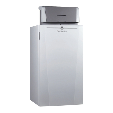
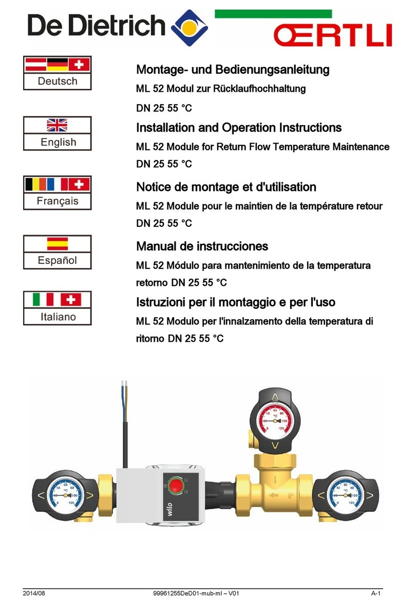
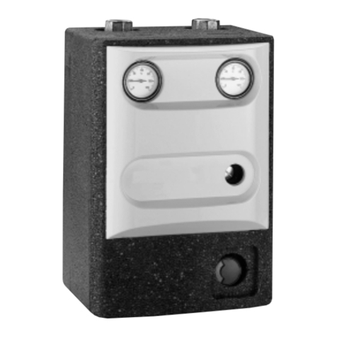
DeDietrich VM Diematic Evolution Troubleshooting guide

ADVANCE
S U S T A I N A B L E C O M F O R T
®
MW-4000218-1
en
Installation, User and Service Manual
VM Diematic Evolution
AD315

Contents
1 Safety . . . . . . . . . . . . . . . . . . . . . . . . . . . . . . . . . . . . . . . . . . . . . . . . . . . . . . . . . . . . . . . . . . . . . . . . . . . . . . . . . . . . . . . . . . . . 4
1.1 General safety instructions . . . . . . . . . . . . . . . . . . . . . . . . . . . . . . . . . . . . . . . . . . . . . . . . . . . . . . . . . . . . . . . . . . . . . . . 4
1.2 Recommendations . . . . . . . . . . . . . . . . . . . . . . . . . . . . . . . . . . . . . . . . . . . . . . . . . . . . . . . . . . . . . . . . . . . . . . . . . . . . . 4
1.3 Liabilities . . . . . . . . . . . . . . . . . . . . . . . . . . . . . . . . . . . . . . . . . . . . . . . . . . . . . . . . . . . . . . . . . . . . . . . . . . . . . . . . . . . . . 5
1.3.1 Manufacturer's liability . . . . . . . . . . . . . . . . . . . . . . . . . . . . . . . . . . . . . . . . . . . . . . . . . . . . . . . . . . . . . . . . . . . 5
1.3.2 Installer's liability . . . . . . . . . . . . . . . . . . . . . . . . . . . . . . . . . . . . . . . . . . . . . . . . . . . . . . . . . . . . . . . . . . . . . . . 5
1.3.3 User's liability . . . . . . . . . . . . . . . . . . . . . . . . . . . . . . . . . . . . . . . . . . . . . . . . . . . . . . . . . . . . . . . . . . . . . . . . . .5
2 About this manual . . . . . . . . . . . . . . . . . . . . . . . . . . . . . . . . . . . . . . . . . . . . . . . . . . . . . . . . . . . . . . . . . . . . . . . . . . . . . . . . . . . 6
2.1 Symbols used . . . . . . . . . . . . . . . . . . . . . . . . . . . . . . . . . . . . . . . . . . . . . . . . . . . . . . . . . . . . . . . . . . . . . . . . . . . . . . . . . 6
2.1.1 Symbols used in the manual . . . . . . . . . . . . . . . . . . . . . . . . . . . . . . . . . . . . . . . . . . . . . . . . . . . . . . . . . . . . . . 6
2.1.2 Symbols used on the appliance . . . . . . . . . . . . . . . . . . . . . . . . . . . . . . . . . . . . . . . . . . . . . . . . . . . . . . . . . . . .6
3 Technical specifications . . . . . . . . . . . . . . . . . . . . . . . . . . . . . . . . . . . . . . . . . . . . . . . . . . . . . . . . . . . . . . . . . . . . . . . . . . . . . . 7
3.1 Homologations . . . . . . . . . . . . . . . . . . . . . . . . . . . . . . . . . . . . . . . . . . . . . . . . . . . . . . . . . . . . . . . . . . . . . . . . . . . . . . . . 7
3.1.1 Directives . . . . . . . . . . . . . . . . . . . . . . . . . . . . . . . . . . . . . . . . . . . . . . . . . . . . . . . . . . . . . . . . . . . . . . . . . . . . .7
3.1.2 Regulations and standards . . . . . . . . . . . . . . . . . . . . . . . . . . . . . . . . . . . . . . . . . . . . . . . . . . . . . . . . . . . . . . . 7
3.1.3 Additional directives . . . . . . . . . . . . . . . . . . . . . . . . . . . . . . . . . . . . . . . . . . . . . . . . . . . . . . . . . . . . . . . . . . . . .7
3.1.4 Factory test . . . . . . . . . . . . . . . . . . . . . . . . . . . . . . . . . . . . . . . . . . . . . . . . . . . . . . . . . . . . . . . . . . . . . . . . . . . 7
3.2 Technical data . . . . . . . . . . . . . . . . . . . . . . . . . . . . . . . . . . . . . . . . . . . . . . . . . . . . . . . . . . . . . . . . . . . . . . . . . . . . . . . . .7
3.3 Dimensions . . . . . . . . . . . . . . . . . . . . . . . . . . . . . . . . . . . . . . . . . . . . . . . . . . . . . . . . . . . . . . . . . . . . . . . . . . . . . . . . . . . 8
3.4 Internal connections of the VM Diematic Evolution housing . . . . . . . . . . . . . . . . . . . . . . . . . . . . . . . . . . . . . . . . . . . . . . 9
4 Description of the product . . . . . . . . . . . . . . . . . . . . . . . . . . . . . . . . . . . . . . . . . . . . . . . . . . . . . . . . . . . . . . . . . . . . . . . . . . . . 10
4.1 General description . . . . . . . . . . . . . . . . . . . . . . . . . . . . . . . . . . . . . . . . . . . . . . . . . . . . . . . . . . . . . . . . . . . . . . . . . . . .10
4.2 Main components . . . . . . . . . . . . . . . . . . . . . . . . . . . . . . . . . . . . . . . . . . . . . . . . . . . . . . . . . . . . . . . . . . . . . . . . . . . . . 10
4.3 PCBs . . . . . . . . . . . . . . . . . . . . . . . . . . . . . . . . . . . . . . . . . . . . . . . . . . . . . . . . . . . . . . . . . . . . . . . . . . . . . . . . . . . . . . .10
4.3.1 Description of the EEC-01 PCB . . . . . . . . . . . . . . . . . . . . . . . . . . . . . . . . . . . . . . . . . . . . . . . . . . . . . . . . . . .10
4.3.2 Description of the CB–05 connection PCB . . . . . . . . . . . . . . . . . . . . . . . . . . . . . . . . . . . . . . . . . . . . . . . . . . 12
4.4 Standard delivery . . . . . . . . . . . . . . . . . . . . . . . . . . . . . . . . . . . . . . . . . . . . . . . . . . . . . . . . . . . . . . . . . . . . . . . . . . . . . 12
4.5 Accessories & options . . . . . . . . . . . . . . . . . . . . . . . . . . . . . . . . . . . . . . . . . . . . . . . . . . . . . . . . . . . . . . . . . . . . . . . . . .12
5 Before installation . . . . . . . . . . . . . . . . . . . . . . . . . . . . . . . . . . . . . . . . . . . . . . . . . . . . . . . . . . . . . . . . . . . . . . . . . . . . . . . . . . 14
5.1 Installation regulations . . . . . . . . . . . . . . . . . . . . . . . . . . . . . . . . . . . . . . . . . . . . . . . . . . . . . . . . . . . . . . . . . . . . . . . . . 14
5.2 Electrical power supply . . . . . . . . . . . . . . . . . . . . . . . . . . . . . . . . . . . . . . . . . . . . . . . . . . . . . . . . . . . . . . . . . . . . . . . . . 14
5.3 Choice of the location . . . . . . . . . . . . . . . . . . . . . . . . . . . . . . . . . . . . . . . . . . . . . . . . . . . . . . . . . . . . . . . . . . . . . . . . . . 14
5.3.1 Data plate . . . . . . . . . . . . . . . . . . . . . . . . . . . . . . . . . . . . . . . . . . . . . . . . . . . . . . . . . . . . . . . . . . . . . . . . . . . 14
5.3.2 Position of the appliance . . . . . . . . . . . . . . . . . . . . . . . . . . . . . . . . . . . . . . . . . . . . . . . . . . . . . . . . . . . . . . . . 15
6 Connecting diagrams and configuration . . . . . . . . . . . . . . . . . . . . . . . . . . . . . . . . . . . . . . . . . . . . . . . . . . . . . . . . . . . . . . . . . 16
6.1 Factory settings for circuits . . . . . . . . . . . . . . . . . . . . . . . . . . . . . . . . . . . . . . . . . . . . . . . . . . . . . . . . . . . . . . . . . . . . . . 16
6.2 Addition of 2 heating circuits + 1 DHW circuit + 1 swimming pool circuit controlled by VM Diematic Evolution . . . . . . 16
6.2.1 Electrical connections . . . . . . . . . . . . . . . . . . . . . . . . . . . . . . . . . . . . . . . . . . . . . . . . . . . . . . . . . . . . . . . . . . 17
6.2.2 System configuration . . . . . . . . . . . . . . . . . . . . . . . . . . . . . . . . . . . . . . . . . . . . . . . . . . . . . . . . . . . . . . . . . . . 18
6.3 Cascade of 3 generators, 3 heating circuits and 1 DHW circuit controlled by VM Diematic Evolution . . . . . . . . . . . . . 19
6.3.1 Electrical connections . . . . . . . . . . . . . . . . . . . . . . . . . . . . . . . . . . . . . . . . . . . . . . . . . . . . . . . . . . . . . . . . . . 20
6.3.2 System configuration . . . . . . . . . . . . . . . . . . . . . . . . . . . . . . . . . . . . . . . . . . . . . . . . . . . . . . . . . . . . . . . . . . . 21
6.4 Cascade of 2 generators + addition of 3 heating circuits + 1 DHW circuit controlled by VM Diematic Evolution . . . . . 22
6.4.1 Electrical connections . . . . . . . . . . . . . . . . . . . . . . . . . . . . . . . . . . . . . . . . . . . . . . . . . . . . . . . . . . . . . . . . . . 24
6.4.2 System configuration . . . . . . . . . . . . . . . . . . . . . . . . . . . . . . . . . . . . . . . . . . . . . . . . . . . . . . . . . . . . . . . . . . . 24
7 Installer instructions . . . . . . . . . . . . . . . . . . . . . . . . . . . . . . . . . . . . . . . . . . . . . . . . . . . . . . . . . . . . . . . . . . . . . . . . . . . . . . . . .26
7.1 Reversing the opening direction of the box door . . . . . . . . . . . . . . . . . . . . . . . . . . . . . . . . . . . . . . . . . . . . . . . . . . . . . 26
7.2 Accessing the connection terminal block . . . . . . . . . . . . . . . . . . . . . . . . . . . . . . . . . . . . . . . . . . . . . . . . . . . . . . . . . . . 26
7.2.1 Cable routing . . . . . . . . . . . . . . . . . . . . . . . . . . . . . . . . . . . . . . . . . . . . . . . . . . . . . . . . . . . . . . . . . . . . . . . . . 26
7.3 Fit the housing to the wall . . . . . . . . . . . . . . . . . . . . . . . . . . . . . . . . . . . . . . . . . . . . . . . . . . . . . . . . . . . . . . . . . . . . . . . 27
7.4 Connecting the box to a generator or to another box . . . . . . . . . . . . . . . . . . . . . . . . . . . . . . . . . . . . . . . . . . . . . . . . . . 27
7.4.1 Connect an S-BUS cable . . . . . . . . . . . . . . . . . . . . . . . . . . . . . . . . . . . . . . . . . . . . . . . . . . . . . . . . . . . . . . . .27
7.4.2 Connect a Mod-BUS cable . . . . . . . . . . . . . . . . . . . . . . . . . . . . . . . . . . . . . . . . . . . . . . . . . . . . . . . . . . . . . . 27
7.5 Selecting the operating mode . . . . . . . . . . . . . . . . . . . . . . . . . . . . . . . . . . . . . . . . . . . . . . . . . . . . . . . . . . . . . . . . . . . . 28
7.5.1 Using the VM Diematic Evolution box as an extension box . . . . . . . . . . . . . . . . . . . . . . . . . . . . . . . . . . . . . .28
7.5.2 Using the VM Diematic Evolution box as a mixed control box . . . . . . . . . . . . . . . . . . . . . . . . . . . . . . . . . . . .28
7.6 Configuring the installation . . . . . . . . . . . . . . . . . . . . . . . . . . . . . . . . . . . . . . . . . . . . . . . . . . . . . . . . . . . . . . . . . . . . . . 29
7.6.1 Control panel description . . . . . . . . . . . . . . . . . . . . . . . . . . . . . . . . . . . . . . . . . . . . . . . . . . . . . . . . . . . . . . . .29
Contents
2 7703592 - v02 - 14062018

7.6.2 Definition of zone and activity . . . . . . . . . . . . . . . . . . . . . . . . . . . . . . . . . . . . . . . . . . . . . . . . . . . . . . . . . . . . 30
7.6.3 Personalising the control panel . . . . . . . . . . . . . . . . . . . . . . . . . . . . . . . . . . . . . . . . . . . . . . . . . . . . . . . . . . . 30
7.6.4 Changing the name of an activity . . . . . . . . . . . . . . . . . . . . . . . . . . . . . . . . . . . . . . . . . . . . . . . . . . . . . . . . . 30
7.6.5 Personalising the name and symbol for a zone . . . . . . . . . . . . . . . . . . . . . . . . . . . . . . . . . . . . . . . . . . . . . . .31
8 Commissioning . . . . . . . . . . . . . . . . . . . . . . . . . . . . . . . . . . . . . . . . . . . . . . . . . . . . . . . . . . . . . . . . . . . . . . . . . . . . . . . . . . . . 32
8.1 Initial commissioning (or after an update) . . . . . . . . . . . . . . . . . . . . . . . . . . . . . . . . . . . . . . . . . . . . . . . . . . . . . . . . . . . 32
8.2 Accessing the Installer level . . . . . . . . . . . . . . . . . . . . . . . . . . . . . . . . . . . . . . . . . . . . . . . . . . . . . . . . . . . . . . . . . . . . . 32
8.3 Room temperature for a zone . . . . . . . . . . . . . . . . . . . . . . . . . . . . . . . . . . . . . . . . . . . . . . . . . . . . . . . . . . . . . . . . . . . . 32
8.3.1 Selecting the operating mode . . . . . . . . . . . . . . . . . . . . . . . . . . . . . . . . . . . . . . . . . . . . . . . . . . . . . . . . . . . . 32
8.3.2 Changing the temperature settings of a zone . . . . . . . . . . . . . . . . . . . . . . . . . . . . . . . . . . . . . . . . . . . . . . . . 32
8.3.3 Changing the room temperature temporarily . . . . . . . . . . . . . . . . . . . . . . . . . . . . . . . . . . . . . . . . . . . . . . . . . 33
8.3.4 Timer programming for heating . . . . . . . . . . . . . . . . . . . . . . . . . . . . . . . . . . . . . . . . . . . . . . . . . . . . . . . . . . . 33
8.4 Domestic hot water temperature . . . . . . . . . . . . . . . . . . . . . . . . . . . . . . . . . . . . . . . . . . . . . . . . . . . . . . . . . . . . . . . . . .33
8.4.1 Choosing the domestic hot water operating mode . . . . . . . . . . . . . . . . . . . . . . . . . . . . . . . . . . . . . . . . . . . . 33
8.4.2 Forcing domestic hot water production (override) . . . . . . . . . . . . . . . . . . . . . . . . . . . . . . . . . . . . . . . . . . . . . 34
8.4.3 Modifying the domestic hot water set point temperatures . . . . . . . . . . . . . . . . . . . . . . . . . . . . . . . . . . . . . . . 34
8.4.4 Timer programming for domestic hot water . . . . . . . . . . . . . . . . . . . . . . . . . . . . . . . . . . . . . . . . . . . . . . . . . . 34
8.5 Activating the holiday program . . . . . . . . . . . . . . . . . . . . . . . . . . . . . . . . . . . . . . . . . . . . . . . . . . . . . . . . . . . . . . . . . . . 35
8.6 Drying screed . . . . . . . . . . . . . . . . . . . . . . . . . . . . . . . . . . . . . . . . . . . . . . . . . . . . . . . . . . . . . . . . . . . . . . . . . . . . . . . . 35
8.7 Setting the heating curve . . . . . . . . . . . . . . . . . . . . . . . . . . . . . . . . . . . . . . . . . . . . . . . . . . . . . . . . . . . . . . . . . . . . . . . 36
8.8 Saving the installer details . . . . . . . . . . . . . . . . . . . . . . . . . . . . . . . . . . . . . . . . . . . . . . . . . . . . . . . . . . . . . . . . . . . . . . 36
8.9 Saving the commissioning settings . . . . . . . . . . . . . . . . . . . . . . . . . . . . . . . . . . . . . . . . . . . . . . . . . . . . . . . . . . . . . . . .36
8.10 Cascade operation . . . . . . . . . . . . . . . . . . . . . . . . . . . . . . . . . . . . . . . . . . . . . . . . . . . . . . . . . . . . . . . . . . . . . . . . . . . . 37
8.10.1 Managing a traditional cascade . . . . . . . . . . . . . . . . . . . . . . . . . . . . . . . . . . . . . . . . . . . . . . . . . . . . . . . . . . .37
8.10.2 Managing a parallel cascade . . . . . . . . . . . . . . . . . . . . . . . . . . . . . . . . . . . . . . . . . . . . . . . . . . . . . . . . . . . . .38
9 Menu tree . . . . . . . . . . . . . . . . . . . . . . . . . . . . . . . . . . . . . . . . . . . . . . . . . . . . . . . . . . . . . . . . . . . . . . . . . . . . . . . . . . . . . . . . 39
9.1 Menu - Installation Setup . . . . . . . . . . . . . . . . . . . . . . . . . . . . . . . . . . . . . . . . . . . . . . . . . . . . . . . . . . . . . . . . . . . . . . . 39
9.2 Menu - Advanced Service Menu . . . . . . . . . . . . . . . . . . . . . . . . . . . . . . . . . . . . . . . . . . . . . . . . . . . . . . . . . . . . . . . . . .40
9.3 Menu - Error History . . . . . . . . . . . . . . . . . . . . . . . . . . . . . . . . . . . . . . . . . . . . . . . . . . . . . . . . . . . . . . . . . . . . . . . . . . . 40
9.4 Menu - System Settings . . . . . . . . . . . . . . . . . . . . . . . . . . . . . . . . . . . . . . . . . . . . . . . . . . . . . . . . . . . . . . . . . . . . . . . . 40
9.5 Menu - Version Information . . . . . . . . . . . . . . . . . . . . . . . . . . . . . . . . . . . . . . . . . . . . . . . . . . . . . . . . . . . . . . . . . . . . . .41
9.6 Sub-menus - Parameters, counters, signals . . . . . . . . . . . . . . . . . . . . . . . . . . . . . . . . . . . . . . . . . . . . . . . . . . . . . . . . .41
10 Maintaining the installation . . . . . . . . . . . . . . . . . . . . . . . . . . . . . . . . . . . . . . . . . . . . . . . . . . . . . . . . . . . . . . . . . . . . . . . . . . . 45
10.1 Viewing the service notifications . . . . . . . . . . . . . . . . . . . . . . . . . . . . . . . . . . . . . . . . . . . . . . . . . . . . . . . . . . . . . . . . . . 45
10.2 Resetting or re-establishing the parameters. . . . . . . . . . . . . . . . . . . . . . . . . . . . . . . . . . . . . . . . . . . . . . . . . . . . . . . . . 45
10.2.1 Auto-detecting options and accessories . . . . . . . . . . . . . . . . . . . . . . . . . . . . . . . . . . . . . . . . . . . . . . . . . . . . 45
10.2.2 Reverting to the commissioning settings . . . . . . . . . . . . . . . . . . . . . . . . . . . . . . . . . . . . . . . . . . . . . . . . . . . . 45
10.2.3 Reverting to the factory settings . . . . . . . . . . . . . . . . . . . . . . . . . . . . . . . . . . . . . . . . . . . . . . . . . . . . . . . . . . 45
10.3 Accessing information on the hardware and software versions . . . . . . . . . . . . . . . . . . . . . . . . . . . . . . . . . . . . . . . . . . 45
11 Troubleshooting . . . . . . . . . . . . . . . . . . . . . . . . . . . . . . . . . . . . . . . . . . . . . . . . . . . . . . . . . . . . . . . . . . . . . . . . . . . . . . . . . . . .46
11.1 Error codes . . . . . . . . . . . . . . . . . . . . . . . . . . . . . . . . . . . . . . . . . . . . . . . . . . . . . . . . . . . . . . . . . . . . . . . . . . . . . . . . . . 46
11.2 List of error codes . . . . . . . . . . . . . . . . . . . . . . . . . . . . . . . . . . . . . . . . . . . . . . . . . . . . . . . . . . . . . . . . . . . . . . . . . . . . . 46
11.3 Displaying and clearing the error memory . . . . . . . . . . . . . . . . . . . . . . . . . . . . . . . . . . . . . . . . . . . . . . . . . . . . . . . . . . 46
12 Warranty . . . . . . . . . . . . . . . . . . . . . . . . . . . . . . . . . . . . . . . . . . . . . . . . . . . . . . . . . . . . . . . . . . . . . . . . . . . . . . . . . . . . . . . . . 47
12.1 General . . . . . . . . . . . . . . . . . . . . . . . . . . . . . . . . . . . . . . . . . . . . . . . . . . . . . . . . . . . . . . . . . . . . . . . . . . . . . . . . . . . . . 47
12.2 Terms of warranty . . . . . . . . . . . . . . . . . . . . . . . . . . . . . . . . . . . . . . . . . . . . . . . . . . . . . . . . . . . . . . . . . . . . . . . . . . . . . 47
13 Spare parts . . . . . . . . . . . . . . . . . . . . . . . . . . . . . . . . . . . . . . . . . . . . . . . . . . . . . . . . . . . . . . . . . . . . . . . . . . . . . . . . . . . . . . . 49
13.1 General . . . . . . . . . . . . . . . . . . . . . . . . . . . . . . . . . . . . . . . . . . . . . . . . . . . . . . . . . . . . . . . . . . . . . . . . . . . . . . . . . . . . . 49
13.2 Spare parts . . . . . . . . . . . . . . . . . . . . . . . . . . . . . . . . . . . . . . . . . . . . . . . . . . . . . . . . . . . . . . . . . . . . . . . . . . . . . . . . . . 49
13.2.1 VM Diematic Evolution box . . . . . . . . . . . . . . . . . . . . . . . . . . . . . . . . . . . . . . . . . . . . . . . . . . . . . . . . . . . . . . 49
Contents
7703592 - v02 - 14062018 3

1 Safety
1.1 General safety instructions
Danger
This appliance can be used by children aged from
8 years and above and persons with reduced
physical, sensory or mental capabilities or lack of
experience and knowledge if they have been
given supervision or instruction concerning use of
the appliance in a safe way and understand the
hazards involved. Children shall not play with the
appliance. Cleaning and user maintenance shall
not be made by children without supervision.
Danger
If you smell flue gases:
1. Switch off the appliance.
2. Open the windows.
3. Locate the probable source of the flue gas
leak and fix it immediately.
1.2 Recommendations
Important
Keep this document close to the place where the
appliance is installed.
Casing components
Remove the casing only to perform maintenance and
repair work. Put the casing back in place after
maintenance and repair work.
Warning stickers
The instructions and warnings affixed to the appliance
must never be removed or covered and must remain
legible during the entire lifespan of the appliance.
Immediately replace damaged or illegible instructions
and warning stickers.
Modifications
Modifications to the box require the written approval of
De Dietrich.
1 Safety
4 7703592 - v02 - 14062018

1.3 Liabilities
1.3.1 Manufacturer's liability
Our products are manufactured in compliance with the
requirements of the various Directives applicable. They
are therefore delivered with the marking and any
documents necessary. In the interests of the quality of
our products, we strive constantly to improve them. We
therefore reserve the right to modify the specifications
given in this document.
Our liability as manufacturer may not be invoked in the
following cases:
Failure to abide by the instructions on installing and
maintaining the appliance.
Failure to abide by the instructions on using the
appliance.
Faulty or insufficient maintenance of the appliance.
1.3.2 Installer's liability
The installer is responsible for the installation and initial
commissioning of the appliance. The installer must
observe the following instructions:
Read and follow the instructions given in the manuals
provided with the appliance.
Install the appliance in compliance with prevailing
legislation and standards.
Carry out initial commissioning and any checks
necessary.
Explain the installation to the user.
If maintenance is necessary, warn the user of the
obligation to check the appliance and keep it in good
working order.
Give all the instruction manuals to the user.
1.3.3 User's liability
To guarantee optimum operation of the system, you
must abide by the following instructions:
Read and follow the instructions given in the manuals
provided with the appliance.
Call on a qualified professional to carry out installation
and initial commissioning.
Get your installer to explain your installation to you.
Have the required inspections and maintenance
carried out by a qualified installer.
Keep the instruction manuals in good condition close
to the appliance.
1 Safety
7703592 - v02 - 14062018 5

2 About this manual
2.1 Symbols used
2.1.1 Symbols used in the manual
This manual uses various danger levels to draw attention to special
instructions. We do this to improve user safety, to prevent problems and to
guarantee correct operation of the appliance.
Danger
Risk of dangerous situations that may result in serious personal
injury.
Danger of electric shock
Risk of electric shock.
Warning
Risk of dangerous situations that may result in minor personal
injury.
Caution
Risk of material damage.
Important
Please note: important information.
See
Reference to other manuals or pages in this manual.
2.1.2 Symbols used on the appliance
1Alternating current.
2Protective earthing.
3Before installing and commissioning the appliance, carefully read
the instruction manuals provided.
4Dispose of used products through an appropriate recovery and
recycling structure.
5Caution: danger of electric shock, live parts. Disconnect the mains
power prior to carrying out any work.
6Connect the appliance to the protective earthing.
Fig.1
1 2
MW-1000123-2
1
2
3
4
5
6
2 About this manual
6 7703592 - v02 - 14062018

3 Technical specifications
3.1 Homologations
3.1.1 Directives
This product complies with the requirements of the following European
Directives and Standards:
Standards: EN15034, EN303.1 and EN303.2
Efficiency Directive 92/42/EC
Low Voltage Directive 2014/35/EU
Generic standard: EN 60335-1
Electromagnetic Compatibility Directive 2014/30/EU
Generic standards: EN 61000-6-3, EN 61000-6-1
Relevant Standard: EN 55014
In addition to the legal requirements and guidelines, the supplementary
guidelines in this manual must also be followed.
Supplements or subsequent regulations and guidelines that are valid at
the time of installation shall apply to all regulations and guidelines
specified in this manual.
Warning
The appliance must be installed by a qualified professional in
accordance with prevailing local and national regulations.
3.1.2 Regulations and standards
Beside the general technical rules, the relevant standards, regulations,
ordinances and guidelines should be followed:
IEC/EN 60335-1
EnEV Energy Saving Ordinance
Regulations from the local electricity supplier
Obligation to register (in some cases, Group Exemption Regulation )
3.1.3 Additional directives
In addition to the legal requirements and guidelines, the supplementary
guidelines in this manual must also be followed.
Supplements or subsequent regulations and guidelines that are valid at
the time of installation shall apply to all regulations and guidelines
specified in this manual.
Warning
The appliance must be installed by a qualified professional in
accordance with applicable local and national regulations.
3.1.4 Factory test
Before leaving the factory, each appliance is tested for the following:
Electrical tests (components, safety).
3.2 Technical data
Power supply: 230 V - 50 Hz
Power: 10 - 1450 W
3 Technical specifications
7703592 - v02 - 14062018 7

3.3 Dimensions
Fig.2
642
281
325
168
12.5
281
240
230
28 28 28 28 28 28
20
45 45 45 45
22.5 45 45 45
84 84
140.5140.5
37
281
75.5
MW-1001097-1
3 Technical specifications
8 7703592 - v02 - 14062018

3.4 Internal connections of the VM Diematic Evolution housing
Fig.3
1
2
3
4
X3-EEC01
1 2 3 4 5
1 2 3 4 5
WH
BR
YW
GY
GN
X2-CB05
BL
BR
BL
BR
ZG1
ZG1a
3
4
1
2
A
X16
X2
X5
1 3 2
X12-EEC01
GN/YW
2 1 3
C
X2-EEC01
1 2 3 4 5
X5-EEC01
1 2 3 4 5
X4-CB05
1 2 3 4 5 6
1 2 3 4 5 6
X4-EEC01
X16-EEC01
1 2 3 4 5 6
1 2 3 4 5 6
CB05
EEC01
X3
X4
X12
X2
X4
MW-4000222-02(=>BE)
3 Technical specifications
7703592 - v02 - 14062018 9

4 Description of the product
4.1 General description
The VM Diematic Evolution box can be used as an extension box to
increase the number of secondary zones that are controlled, including the
domestic hot water and the swimming pool.
The box is fully compatible with the new D-Evolution control system range
and backwards compatible with Diematic, but only in slave mode.
The box is:
fully compatible with the new D-Evolution control system range
backwards compatible with Diematic control systems, but only if
connected in slave mode.
4.2 Main components
1Door
2Access cover to the connection terminal block
3Diematic Evolution control panel
4Technical service connector
5ON/OFF switch
6EEC-01 PCB
7CB–05 PCB
8S-Bus sockets
4.3 PCBs
4.3.1 Description of the EEC-01 PCB
Different heating zones can be connected to the EEC-01 PCB. Two zones
are designated for heating and one for domestic hot water. The
connections for the sensors or pumps of each zone are on the PCB.
The EEC-01 PCB can also be used for cascade regulation.
Fig.4
1
5
4
3
2
8
6
7
MW-1001099-1
4 Description of the product
10 7703592 - v02 - 14062018

Fig.5
MW-1001101-2
5
17 16 15 14 13 12 11 10 9 8 7 6
18
4 3 2 1
22
192123 20
X2 X3
1Room temperature sensor - circuit A
2Room temperature sensor - circuit B
3Room temperature sensor - circuit C
4Programmable and 0 - 10 V input
5Outdoor temperature sensor
6Impressed current anode
7Flow sensor - circuit A
8Flow sensor - circuit B
9Flow sensor - circuit C
10 Domestic hot water sensor
11 System sensor 2
12 System sensor 1
13 Pump and safety thermostat - circuit A
14 Three-way valve - circuit A
15 Pump and safety thermostat - circuit B
16 3-way valve - circuit B
17 Domestic hot water tank pump
18 Connectors for S-BUS cables to CB–05 PCB
19 L-BUS connection (END connector)
20 L-BUS connection to the Diematic Evolution control
panel
21 S-BUS connector to connector on the fascia
22 Mod-BUS connectors to iSystem control panel in
cascade mode
23 Coding wheel, selects the generator number in the
cascade in Mod-Bus
Tab.1 Compatibility of connections
Circuit A Circuit B Circuit C
(with AD249 op
tion)
AUX circuit
(with AD249 op
tion)
Domestic hot wa
ter circuit
Convection fan Yes Yes Yes No No
Underfloor heating Yes Yes Yes No No
Radiator Yes Yes Yes No No
365 day radiator Yes Yes Yes No No
Continuous heating Yes Yes Yes No No
Timer programme Yes Yes Yes Yes Yes
Swimming pool Yes Yes Yes No No
4 Description of the product
7703592 - v02 - 14062018 11

Circuit A Circuit B Circuit C
(with AD249 op
tion)
AUX circuit
(with AD249 op
tion)
Domestic hot wa
ter circuit
Domestic hot water produc
tion
Yes Yes Yes Yes Yes
Domestic hot water produc
tion, electric only
Yes Yes Yes No No
Stratified tank (2 sensors) No No No No Yes
Deactivation Yes Yes Yes Yes Yes
4.3.2 Description of the CB–05 connection PCB
The connection PCB connects the power supply and the S-Bus to the box.
1Electrical power supply
2S-BUS connection to the EEC-01 PCB
3S-BUS connection to other boxes or generators
4.4 Standard delivery
The delivery includes:
the housing
the connectors
the cable glands
the installation, use and maintenance manual
4.5 Accessories & options
Various options are available, depending on the configuration of the
installation and the country.
Tab.2
Description Package
S-Bus cable with terminals, 1.5 m AD308
S-Bus cable with terminals, 12 m AD309
S-Bus cable with terminals, 20 m AD310
S-Bus terminals AD321
Fig.6
MW-1001100-1
1
2
3
L
N
4 Description of the product
12 7703592 - v02 - 14062018
Description Package
Mod-Bus connection cable, 1.5 m AD124
Mod-Bus connection cable, 12 m AD134
Mod-Bus connection cable, 40 m DB119
PCB + sensor for three-way valve AD249
Domestic hot water sensor and TAS AD212
Flow sensor after valve AD199
Sensor for buffer tank or cascade flow AD250
Outdoor temperature sensor FM46
Programmable room thermostat AD137
Wireless programmable room thermostat AD200
SmartTC° programmable and connected room thermostat AD324
4 Description of the product
7703592 - v02 - 14062018 13

5 Before installation
5.1 Installation regulations
Caution
The appliance must be installed and maintained by a certified
professional in accordance with prevailing statutory texts and
codes of practice.
5.2 Electrical power supply
Tab.3 Electrical information
Power supply voltage 230 V AC/50 Hz
Power supply Single phase
Fuse on the PCB 6.3 AT
Caution
Please ensure the polarities shown on the terminals are followed,
i.e live (L), neutral (N) and earth ( ).
5.3 Choice of the location
Decide on the ideal location, bearing in mind the space the box requires,
as well as any legal requirements.
Install the box on a solid and stable structure.
Caution
The box must be installed in a frost-free environment.
5.3.1 Data plate
The data plates must be accessible at all times. They identify the product
and provide the following information:
Appliance type
Date of manufacture (Year - Week)
Serial number
CE identification number
Electrical power supply
Important
Never remove or cover labels and data plates affixed to the
appliances. Labels and data plates must be legible throughout the
entire lifetime of the appliance.
Damaged or illegible instructions and warning stickers must be
replaced immediately.
Fig.7
MW-1001106-1
5 Before installation
14 7703592 - v02 - 14062018
5.3.2 Position of the appliance
Caution
When installing appliances, respect the IP21 protection rating.
Allow sufficient space around the housing to allow access and facilitate
maintenance. The minimum recommended dimensions are shown in the
illustration in mm.
As standard, the control panel access door opens to the left. If the door's
opening direction is reversed, ensure there is sufficient space on the
right-hand side.
Fig.8
MW-1001102-1
50 20
463
20
200
5 Before installation
7703592 - v02 - 14062018 15
6 Connecting diagrams and configuration
6.1 Factory settings for circuits
In the factory, the different circuits are configured as indicated in the table.
You can modify this configuration and adapt it to the needs of your
installation. Three installation types are described here to provide a guide.
Tab.4
Circuit Circuit type Specifications
CIRCA Direct heating circuit Gradient: 1.5
Maximum temperature: 90 °C
CIRCB
CIRCC (optional)
AUX (optional)
Circuit with mixing valve Gradient: 0.7
Maximum temperature: 50 °C
DHW Domestic hot water circuit Set point temperature: 55 °C
6.2 Addition of 2 heating circuits + 1 DHW circuit + 1 swimming pool circuit controlled by VM
Diematic Evolution
Tab.5 Packages used in this configuration
AD199 Flow sensor after valve
AD249 Three-way valve PCB and sensor
AD212 (x3) Domestic hot water sensor and TAS
AD309 S-Bus 12 m cable with terminals
AD311 SmartTC° programmable and connected room thermostat
AD250 Sensor for buffer tank or cascade flow
6 Connecting diagrams and configuration
16 7703592 - v02 - 14062018
Fig.9
MW-4000221-2
4
4
4
4
4
4
10
27
9
10
11b
11b
27
9
9
9
9
9
23
44
23
44
65
65
65
67
11b
27
4
4
4
50
10
17
4
4
34
34
3
7
4
230V/50Hz
SA19
2xAD 199
+
75
112c
99
11d
27
°C °C
27
21
44 4
10
27
9
9
9
9
65
64
67
27
11b
23
44
11b
4 4
10
4
23
9
9
27
32
7
99
28
9
29
30
25
56
24
9
26
B...
AD212
AD212
33a
AD212 33b
AD 309
S-BUS
AD249
AD 199
+
AUX
LL
CIRCA CIRCB CIRCC
FOLLOWER
MASTER
4Pressure gauge
7Automatic air vent
9Isolation valve
10 Three-way mixing valve
11b Pump for heating circuit with mixing valve
11d Swimming pool primary circuit pump
21 Outdoor temperature sensor
23 Flow temperature sensor
24 Domestic hot water tank exchanger primary inlet
25 Domestic hot water tank exchanger primary outlet
26 DHW booster pump
27 Non-return valve
28 Domestic cold water inlet
29 Pressure reducer
32 Domestic hot water circulation loop pump
33a Domestic hot water temperature sensor, high
position
33b Domestic hot water temperature sensor, low position
34 Primary pump
44 Safety thermostat with manual reset, for underfloor
heating
64 Direct heating circuit
65 Heating circuit with mixing valve
67 Manual radiator valve
75 Pump for DHW use
112c Sensor for swimming pool circuit
6.2.1 Electrical connections
For this configuration, the AD249 and AD309 packages should be installed
for the S-BUS connection.
6 Connecting diagrams and configuration
7703592 - v02 - 14062018 17

1. Make the connections on the master box.
Tab.6
1Domestic hot water circulation loop pump
2DHW booster pump
3Domestic hot water temperature sensor, high position
4Domestic hot water temperature sensor, low position
5Flow temperature sensor after mixing valve
6Pump for heating circuit with mixing valve
7Three-way mixing valve
8"Room Unit" programmable room thermostat
9Safety thermostat with manual reset, for underfloor heating
10 Flow temperature sensor after mixing valve
11 Pump for heating circuit with mixing valve
12 Three-way mixing valve
13 Sensor for swimming pool circuit
14 Swimming pool pump
15 Automatically regulated electronic pump for direct heating circuit
16 Outdoor temperature sensor
17 Sensor for buffer tank or cascade flow
99 Bridging
2. Make the S-BUS connection to the generator.
6.2.2 System configuration
For this hydraulic configuration, certain parameters must be adapted.
1. Select the Cascade Producer Manager Algicon.
2. Select Enable master func.
3. Select Yes.
4. Select the Cascade Producer Manager Algicon.
5. Check the following parameters:
Tab.7
Code Description Adjustment required
NP006 Cascade Type Traditional
NP009 CascInterStageTime 4
NP011 CascadeTypeAlgo Temperature
6. Press the key.
7. Select Installation Setup.
Fig.10
2
1
12 7
14
3 17 4 13 10 5
MW-1001113-2
99611 9
15
16 8
999999
14
13
15
16
17
12
11
10
9
8
6
7
5
1
23
4
CIRCA CIRCB CIRCC
On
6 Connecting diagrams and configuration
18 7703592 - v02 - 14062018

8. Configure the parameters for the following components:
Tab.8
Component Access Parameter Code Adjustment required
Cascade Analogue input > Adv.
Parameters
Sets the general configuration of
the sensor input 2
EP037 System (cascade)
Recirculating pump AUX Functionality of the zone CP024 Time Program
Stratified tank Analogue input > Adv.
Parameters
Sets the general configuration of
the sensor input 1
EP036 DHW tank top
DHW Functionality of the zone CP022 DHW Layered
Swimming pool CIRCC > Parameters,
counters, signals >
Parameters
Functionality of the zone CP023 Swimming pool
6.3 Cascade of 3 generators, 3 heating circuits and 1 DHW circuit controlled by VM Diematic
Evolution
Tab.9 Packages used
AD199 (x2) Flow sensor after valve
AD309 S-Bus cable with terminals, 12 m
AD249 Three-way valve PCB and sensor
AD250 Sensor for buffer tank or cascade flow
6 Connecting diagrams and configuration
7703592 - v02 - 14062018 19

Fig.11
MW-4000219-2
27
21
444 44
10
27
9
10
11b 11b
27
999
9
9
23
44
23
44
6565
64
67
11b
27
4 4 4
10
4
23
9
9
27
32
7
99
28
9
29
30
25
56
24
26
B...
AD212 33a
AD212 33b
AD 309
S-BUS
AD249
2x AD199
+
AUX
LL
AD250
9
CIRCA CIRCB CIRCC
9
9
9
9
9
9
7
3
3
3
4
4
4
7
7
AD308
S-BUS
AD308
S-BUS
SA21
M
M
IniControl 2
IniControl 2
IniControl 2
M
16
9
36
52
50
9
FOLLOWER
MASTER
4Pressure gauge
7Automatic air vent
9Isolation valve
10 Three-way mixing valve
11b Pump for heating circuit with mixing valve
11d Swimming pool primary circuit pump
21 Outdoor temperature sensor
23 Flow temperature sensor
24 Domestic hot water tank exchanger primary inlet
25 Domestic hot water tank exchanger primary outlet
26 DHW booster pump
27 Non-return valve
28 Domestic cold water inlet
29 Pressure reducer
32 Domestic hot water circulation loop pump
33a Domestic hot water temperature sensor, high
position
33b Domestic hot water temperature sensor, low position
34 Primary pump
44 Safety thermostat with manual reset, for underfloor
heating
64 Direct heating circuit
65 Heating circuit with mixing valve
67 Manual radiator valve
75 Pump for DHW use
6.3.1 Electrical connections
For this configuration, the AD249 and AD308 packages should be installed
for the S-BUS connection.
6 Connecting diagrams and configuration
20 7703592 - v02 - 14062018
This manual suits for next models
1
Table of contents
Other DeDietrich Control Unit manuals
Popular Control Unit manuals by other brands

Emerson
Emerson White-Rodgers 36C01 installation instructions

Quectel
Quectel WCDMA UG FILE Series AT Command manual

Edwards
Edwards A528-44-404 instruction manual

Waterworks
Waterworks GUVC16 Service manual

Comelit
Comelit UT8020 Technical manual

Telit Wireless Solutions
Telit Wireless Solutions UL865N3G user guide