DeDietrich EA135 Owner's manual

300021171-001-B
EA135 - EA136
RUES PLITNLENDEFR
Français (page 2)
Notice Technique
Modules hydrauliques
Deutsch (Seite 8)
Technische Anleitung
Hydraulische Heizkreismodule
English (page 14)
Technical instructions
Hydraulic modules
Nederlands (pagina 20)
Technische handleiding
Hydraulische modules
Italiano (pagina 26)
Manuale tecnico
Moduli idraulici
Español (página 32)
Especificaciones técnicas
Módulos hidráulicos
Polski (strona 38)
Instrukcja techniczna
Moduły hydrauliczne
РУССКИЙ (Страница 44)
Техническая инструкция
Гидравлические модули

2EA135 - EA136 14/08/2009 - 300021171-001-B
Français
Sommaire
1 Principaux composants . . . . . . . . . . . . . . . . . . . . . . . . . . . . . . . . . . . . . . . . . . . . . . . . . . . . . . . . . . . . . . . . . . .3
2 Dimensions principales . . . . . . . . . . . . . . . . . . . . . . . . . . . . . . . . . . . . . . . . . . . . . . . . . . . . . . . . . . . . . . . . . . .4
3 Caractéristiques techniques des circulateurs . . . . . . . . . . . . . . . . . . . . . . . . . . . . . . . . . . . . . . . . . . . . . . . . .5
3.1 Circulateurs 3 vitesses . . . . . . . . . . . . . . . . . . . . . . . . . . . . . . . . . . . . . . . . . . . . . . . . . . . . . . . . . . . . . . . . . . . . . . . . . . . . . . . . . . . .5
3.2 Circulateurs électroniques . . . . . . . . . . . . . . . . . . . . . . . . . . . . . . . . . . . . . . . . . . . . . . . . . . . . . . . . . . . . . . . . . . . . . . . . . . . . . . . . .6
4 Caractéristiques techniques de la vanne 3 voies avec bypass 30 %. . . . . . . . . . . . . . . . . . . . . . . . . . . . . . .7

3
14/08/2009 - 300021171-001-B EA135 - EA136
1 Principaux composants
EA 135 : Circuit direct avec pompe A
EA 136 : Circuit vanne 3 voies avec pompe A
1, 2 : Vannes à boisseau sphérique sans entretien avec thermomètre
intégré sur le départ et le retour chauffage.
3: Clapet anti-thermosiphon intégré manoeuvrable par la vanne à
boisseau sphérique.
4: Tubulures et raccords à joints plats G1"1/2 pour des
raccordements au circuit de chauffage.
5: Bouchon
6: Pompe Alpha 2 25-60-180 - Classe A
7: Vanne mélangeuse motorisée 3 voies
8: Commande du Bypass
9: 2 demi-coquilles isolantes
0
20
40 80
100
120
60
°C
0
20
40 80
100
120
60
°C
4
4
5
1
5
2
3
6
9
D000976-C
0
20
40 80
100
120
60
°C
0
20
40 80
100
120
60
°C
4
4
5
1
5
2
3
6
9
8
7
D000977C

4EA135 - EA136 14/08/2009 - 300021171-001-B
2 Dimensions principales
EA 135 : Circuit direct avec pompe A
EA 136 : Circuit vanne 3 voies avec pompe A
Rp : Taraudage
G : Raccordement inférieur, par joint plat
0
20
40 80
100
120
60
°C
0
20
40 80
100
120
60
°C
D000978
Rp 1" Rp 1"
D
B
A
C
G1"1/2 G1"1/2
B
0
20
40 80
100
120
60
°C
0
20
40 80
100
120
60
°C
D000979
Rp 1" Rp 1"
D
B
A
C
G1"1/2
B
G1"1/2
Cote Longueur (mm) Désignation
A 125 Entraxe
B 344 Cote sur plats
C 250 Largeur de l'isolation
D 350 Hauteur de l'isolation

5
14/08/2009 - 300021171-001-B EA135 - EA136
3 Caractéristiques techniques des circulateurs
3.1 Circulateurs 3 vitesses
(kPa)
P
60
40
30
10
0
H
(m)
3
5
6
0
0.0 0.2 0.4 0.6 0.8 1.0 1.2 1.4 2.0 2.2 2.0 2.6 Q(m3/h)
(W)
P1
50
40
20
10
0
30
0.0 0.2 0.4 0.6 0.8 1.2 1.4 1.6 2.0 2.2 2.4 2.6 Q
(m3/h)
E
nerg
y
A
B
C
D
E
F
G
A
ia
e
0.0 0.1 0.2 0.3 0.4 0.5 0.6 Q(l/s)
D000980A
4
2
1
1.6 1.8 2.8
0.7 0.8
20
1.0 1.8 2.8
50
P1Puissance en Watt
HHauteur manométrique en
mètres
PPression disponible en kPa
QDébit (m3/h ou l/s)

6EA135 - EA136 14/08/2009 - 300021171-001-B
3.2 Circulateurs électroniques
- Commande intégrée dans la tête de pompe
- Fonctionnement en mode AUTOADAPT
(Réglage d'usine)
- Régulation par mesure de la pression différentielle (Régulation
par pression différentielle proportionnelle ou par pression
constante)
- Afficheur par LED indiquant la puissance instantanée absorbée
(P1) en Watt.
- Faible niveau de bruit
- Puissant couple de démarrage
- Régime de nuit réduit automatique
- Moteur fonctionnant sur base de la technologie d’un moteur
compact à rotor à aimant permanent
- Convertisseur de fréquence intégré
- Circulateur à purge intégrée
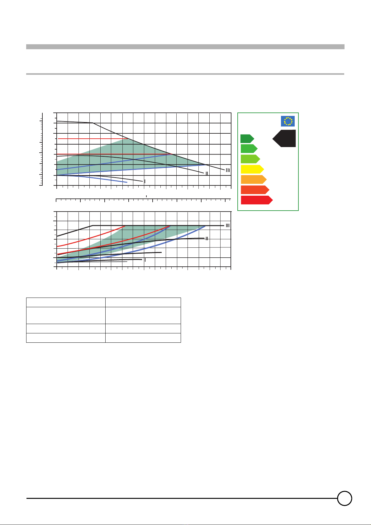
Classe d'énergie
Les circulateurs GRUNDFOS ALPHA2 garantissent la plus faible
consommation électrique et portent le label A.
AUTOADAPT
Le mode de contrôle AUTOADAPT est le réglage d'usine du
circulateur. Réglée en mode AUTOADAPT, la pompe s’adapte
automatiquement suivant la demande de l’installation de chauffage.
Le réglage "AUTOADAPT" peut être utilisé pour les installations
bitubes ainsi que pour les systèmes de chauffage par le sol.
Régulation par mesure de la pression
différentielle
La régulation par mesure de pression différentielle intégrée permet
au circulateur de s’adapter automatiquement aux modifications des
besoins de chauffage.
Régime de nuit réduit automatique
Le circulateur commute automatiquement du régime de jour vers le
régime réduit de nuit en contrôlant la température de l’eau de départ.
Vitesses fixes
Le circulateur possède trois vitesses fixes (I, II et III). Lorsque ce
mode est sélectionné, le circulateur fonctionne suivant une courbe à
vitesse constante.
1: Puissance instantanée absorbée (W)
2: Label d'énergie A
3: Trois vitesses fixes
4: Bouton tactile sélection vitesses fixes
5: Bouton tactile sélection mode nuit
6: Voyant indication mode nuit
7: Voyant indication vitesses fixes
8: Mode contrôle AUTOADAPT (Réglage d'usine)
I
II
III
ALPHA2
AUTO
AUTO
ADPT
1
2
3
4
5
6
7
8
D000981

7
14/08/2009 - 300021171-001-B EA135 - EA136
4 Caractéristiques techniques de la vanne 3 voies
avec bypass 30 %
Matériaux
Bypass réglable
Position "fermé"
Position "ouvert"
Caractéristiques techniques d'une installation
Perte de charge du bypass réglable (totalement ouvert) de la
vanne mélangeuse
Température de service maximale 110 °C
Température de service minimale -20 °C
Pression de service maximale 10 bar
Pression différentielle maximale 2 bar
Angle de réglage possible 90°
Couple moteur nécessaire 3 Nm
Valeur Kvs 4.0
Corps de vanne Laiton Ms58
Axe/boisseau de la vanne Laiton Ms58
Couvercle du corps de vanne Laiton Ms58
Manchon d'entraînement Matière synthétique
Joints toriques Elastomère EPDM
86
48
1"
1"1/2
1"1/2
47
8999
N
9
7
5
3
1
0
1
2
200
150
100
60
40
20
10
5
2
1
501 02 05 100002 400
50
5
30
01
15
40
20 03
12
9
6
3,6
2,4
1,2
0,6
0,3
0,12
m /h
3
l/min
8,0
6,3
4,0
2,5
kvs:
899 19N 15
C5°1
C20°
kW KPa
x
yz
100
10
1
10 100 1000 10 000
0
99 N189 14
mbar
l/h
y
x

8EA135 - EA136 14/08/2009 - 300021171-001-B
Deutsch
Inhaltsverzeichnis
1 Wichtigste Komponenten . . . . . . . . . . . . . . . . . . . . . . . . . . . . . . . . . . . . . . . . . . . . . . . . . . . . . . . . . . . . . . . . . .9
2 Hauptabmessungen . . . . . . . . . . . . . . . . . . . . . . . . . . . . . . . . . . . . . . . . . . . . . . . . . . . . . . . . . . . . . . . . . . . . .10
3 Technische Daten der Umwälzpumpen. . . . . . . . . . . . . . . . . . . . . . . . . . . . . . . . . . . . . . . . . . . . . . . . . . . . . .11
3.1 Umwälzpumpen mit 3 Geschwindigkeiten . . . . . . . . . . . . . . . . . . . . . . . . . . . . . . . . . . . . . . . . . . . . . . . . . . . . . . . . . . . . . . . . . . . .11
3.2 Elektronisch geregelte Umwälzpumpen . . . . . . . . . . . . . . . . . . . . . . . . . . . . . . . . . . . . . . . . . . . . . . . . . . . . . . . . . . . . . . . . . . . . . .12
4 Technische Daten des Dreiwegemischers mit by-pass 30 % . . . . . . . . . . . . . . . . . . . . . . . . . . . . . . . . . . . .13

9
14/08/2009 - 300021171-001-B EA135 - EA136
1 Wichtigste Komponenten
EA 135: Ungemischter Kreis mit Pumpe A
EA 136: Dreiwegemischer-Kreis mit Pumpe A
1, 2: Wartungsfreies Kugelventil mit integriertem Thermometer an
Vorlauf und Heizungsrücklauf.
3: Integrierter Rückflussverhinderer (Schwerkraftbremse), verstellbar
mittels Kugelhahn.
4: Verrohrung und Anschlüsse mit Flachdichtungen G1"1/2 für die
Anschlüsse des Heizkreises.
5: Stopfen
6: Heizungspumpe Alpha 2 25-60-180 - Klasse A
7: Motorbetriebener 3-Wege-Mischer
8: Steuerung des Bypass
9: 2 isolierende Halbschalen
0
20
40 80
100
120
60
°C
0
20
40 80
100
120
60
°C
4
4
5
1
5
2
3
6
9
D000976-C
0
20
40 80
100
120
60
°C
0
20
40 80
100
120
60
°C
4
4
5
1
5
2
3
6
9
8
7
D000977C

10 EA135 - EA136 14/08/2009 - 300021171-001-B
2 Hauptabmessungen
EA 135: Ungemischter Kreis mit Pumpe A
EA 136: Dreiwegemischer-Kreis mit Pumpe A
Rp: Innengewinde
G: Unterer Anschluss, mit Flachdichtung
0
20
40 80
100
120
60
°C
0
20
40 80
100
120
60
°C
D000978
Rp 1" Rp 1"
D
B
A
C
G1"1/2 G1"1/2
B
0
20
40 80
100
120
60
°C
0
20
40 80
100
120
60
°C
D000979
Rp 1" Rp 1"
D
B
A
C
G1"1/2
B
G1"1/2
Mass Länge (mm) Bezeichnung
A 125 Achsabstand
B 344 Höhe auf den Platten
C 250 Breite der Isolierung
D 350 Höhe der Isolierung

11
14/08/2009 - 300021171-001-B EA135 - EA136
3 Technische Daten der Umwälzpumpen
3.1 Umwälzpumpen mit 3 Geschwindigkeiten
(kPa)
P
60
40
30
10
0
H
(m)
3
5
6
0
0.0 0.2 0.4 0.6 0.8 1.0 1.2 1.4 2.0 2.2 2.0 2.6 Q(m3/h)
(W)
P1
50
40
20
10
0
30
0.0 0.2 0.4 0.6 0.8 1.2 1.4 1.6 2.0 2.2 2.4 2.6 Q
(m3/h)
E
nerg
y
A
B
C
D
E
F
G
A
ia
e
0.0 0.1 0.2 0.3 0.4 0.5 0.6 Q(l/s)
D000980A
4
2
1
1.6 1.8 2.8
0.7 0.8
20
1.0 1.8 2.8
50
P1Leistung in Watt
HFörderhöhe in Metern
PVerfügbarer Druck in kPa
QVolumenstrom (m3/Std oder l/s)

12 EA135 - EA136 14/08/2009 - 300021171-001-B
3.2 Elektronisch geregelte Umwälzpumpen
- In den Pumpenkopf integrierte Steuerung
- Betrieb im Modus AUTOADAPT
(Werkseinstellung)
- Regelung durch Messung des Differentialdrucks (Regelung
mittels proportionalem Differentialdruck oder konstantem Druck)
- LED-Anzeige, die die absorbierte Momentanleistung (P1) in Watt
anzeigt.
- Geringer Geräuschpegel
- Kräftiges Anlaufmoment
- Automatische Nachtabsenkung
- Motor mit Kompaktrotor und Permanentmagnet
- Integrierter Frequenzwandler
- Umwälzpumpe mit integrierter Entlüftung
Energieklasse
Die GRUNDFOS ALPHA2 Umwälzpumpen garantieren den
geringsten Energieverbrauch und besitzen die Kennzeichnung A.
AUTOADAPT
Werksseitig ist die Umwälzpumpe auf den Steuerungsmodus
AUTOADAPT eingestellt. Bei der Einstellung AUTOADAPT passt
sich die Pumpe automatisch an den Bedarf der Heizungsanlage an.
Die Einstellung "AUTOADAPT" kann bei Zweirohr-Anlagen sowie
Systemen mit Fußbodenheizung verwendet werden.
Regelung durch Messung des Differentialdrucks
Die integrierte Regelung durch Differentialdruckmessung ermöglicht
die automatische Leistungsanpassung der Umwälzpumpe an
Veränderungen der Heizbedürfnisse.
Automatische Nachtabsenkung
Die Umwälzpumpe schaltet automatisch vom Tagbetrieb auf den
reduzierten Nachtbetrieb um, indem die Wassertemperatur des
Vorlaufs kontrolliert wird.
Fest eingestellte Geschwindigkeiten
Die Umwälzpumpe besitzt drei fest eingestellte Geschwindigkeiten (I,
II und III). Wenn dieser Modus eingestellt ist, arbeitet die
Umwälzpumpe mit einer konstanten Geschwindigkeitskurve.
1: Absorbierte Momentanleistung (W)
2: Energieklasse A
3: Drei fest eingestellte Geschwindigkeiten
4: Drucktaster zur Auswahl der fest eingestellten Geschwindigkeiten
5: Drucktaster zur Auswahl des Nachtbetriebs
6: Leuchte zur Anzeige des Nachtbetriebs
7: Leuchte zur Anzeige der fest eingestellten Geschwindigkeiten
8: Steuerungsmodus AUTOADAPT (Werkseinstellung)
I
II
III
ALPHA2
AUTO
AUTO
ADPT
1
2
3
4
5
6
7
8
D000981

13
14/08/2009 - 300021171-001-B EA135 - EA136
4 Technische Daten des Dreiwegemischers mit by-
pass 30 %
Werkstoffe
Einstellbarer Bypass
Stellung "geschlossen"
Stellung "offen"
Technische Daten einer Anlage
Druckverlust des einstellbaren By-pass (vollständig geöffnet)
des Mischventils
Zulässige Betriebstemperatur 110 °C
Minimale Betriebstemperatur -20 °C
Zulässiger Betriebsüberdruck 10 bar
Maximaler Wirkdruck 2 bar
Möglicher Einstellwinkel 90°
Erforderliches Motormoment 3 Nm
Wert Kvs 4.0
Mischerventil-Körper Laiton Ms58
Achse/Kugelhahn des ventils Laiton Ms58
Deckel des Ventilgehäuses Laiton Ms58
Antriebsmuffe Kunstsoff
O-Dichtungen Elastomer EPDM
86
48
1"
1"1/2
1"1/2
47
8999
N
9
7
5
3
1
0
1
2
200
150
100
60
40
20
10
5
2
1
501 02 05 100002 400
50
5
30
01
15
40
20 03
12
9
6
3,6
2,4
1,2
0,6
0,3
0,12
m /h
3
l/min
8,0
6,3
4,0
2,5
kvs:
899 19N 15
C5°1
C20°
kW KPa
x
yz
100
10
1
10 100 1000 10 000
0
99 N189 14
mbar
l/h
y
x

14 EA135 - EA136 14/08/2009 - 300021171-001-B
English
Contents
1 Main parts. . . . . . . . . . . . . . . . . . . . . . . . . . . . . . . . . . . . . . . . . . . . . . . . . . . . . . . . . . . . . . . . . . . . . . . . . . . . . .15
2 Main dimensions . . . . . . . . . . . . . . . . . . . . . . . . . . . . . . . . . . . . . . . . . . . . . . . . . . . . . . . . . . . . . . . . . . . . . . . .16
3 Technical data on heating pumps . . . . . . . . . . . . . . . . . . . . . . . . . . . . . . . . . . . . . . . . . . . . . . . . . . . . . . . . . .17
3.1 3-speed heating pumps . . . . . . . . . . . . . . . . . . . . . . . . . . . . . . . . . . . . . . . . . . . . . . . . . . . . . . . . . . . . . . . . . . . . . . . . . . . . . . . . . .17
3.2 Electronic heating pumps . . . . . . . . . . . . . . . . . . . . . . . . . . . . . . . . . . . . . . . . . . . . . . . . . . . . . . . . . . . . . . . . . . . . . . . . . . . . . . . . .18
4 Technical specifications of three-way with 30 % by-pass. . . . . . . . . . . . . . . . . . . . . . . . . . . . . . . . . . . . . . .19

15
14/08/2009 - 300021171-001-B EA135 - EA136
1Mainparts
EA 135: Direct circuit with pump A
EA 136: 3-way valve circuit with pump A
1, 2: Maintenance-free ball valves with integrated thermometer on
the heating flow and return.
3: Antithermosiphon valve operated by the spherical plug valve.
4: Piping and G1"1/2 flat gasket fittings for connections to the heating
circuit.
5: Plug
6: Pump Alpha 2 25-60-180 - Class A
7: Motorised 3-way mixing valve
8: Bypass control
9: 2 insulating half-shells
0
20
40 80
100
120
60
°C
0
20
40 80
100
120
60
°C
4
4
5
1
5
2
3
6
9
D000976-C
0
20
40 80
100
120
60
°C
0
20
40 80
100
120
60
°C
4
4
5
1
5
2
3
6
9
8
7
D000977C

16 EA135 - EA136 14/08/2009 - 300021171-001-B
2 Main dimensions
EA 135: Direct circuit with pump A
EA 136: 3-way valve circuit with pump A
Rp: Tapped connection
G: Bottom connection, by flat gasket
0
20
40 80
100
120
60
°C
0
20
40 80
100
120
60
°C
D000978
Rp 1" Rp 1"
D
B
A
C
G1"1/2 G1"1/2
B
0
20
40 80
100
120
60
°C
0
20
40 80
100
120
60
°C
D000979
Rp 1" Rp 1"
D
B
A
C
G1"1/2
B
G1"1/2
Side Length (mm) Description
A 125 Spacer
B 344 Wrench size
C 250 Insulation width
D 350 Insulation height

17
14/08/2009 - 300021171-001-B EA135 - EA136
3 Technical data on heating pumps
3.1 3-speed heating pumps
(kPa)
P
60
40
30
10
0
H
(m)
3
5
6
0
0.0 0.2 0.4 0.6 0.8 1.0 1.2 1.4 2.0 2.2 2.0 2.6 Q(m3/h)
(W)
P1
50
40
20
10
0
30
0.0 0.2 0.4 0.6 0.8 1.2 1.4 1.6 2.0 2.2 2.4 2.6 Q
(m3/h)
E
nerg
y
A
B
C
D
E
F
G
A
ia
e
0.0 0.1 0.2 0.3 0.4 0.5 0.6 Q(l/s)
D000980A
4
2
1
1.6 1.8 2.8
0.7 0.8
20
1.0 1.8 2.8
50
P1Output in Watts
HManometric height in metres
PAvailable pressure in kPa
QFlow rate (m3/h or l/s)

18 EA135 - EA136 14/08/2009 - 300021171-001-B
3.2 Electronic heating pumps
- Control integrated into the pump head
- Operation in AUTOADAPT mode
(Factory setting)
- Control by measuring the differential pressure (Control by
proportional differential pressure or constant pressure)
- LED display showing the instant absorbed power (P1) in Watts.
- Low noise level
- Powerful start-up torque
- Automatic reduced night regime
- Motor operating on the technological basis of a compact rotary
motor with permanent magnet
- Integrated frequency converter
- Heating pump with integrated vent
Energy class
GRUNDFOS ALPHA2 heating pumps guarantee the lowest
electricity consumption and bear label A.
AUTOADAPT
The AUTOADAPT control mode is the heating pump's factory setting.
Set to AUTOADAPT mode, the pump adapts automatically,
depending on the request from the heating system. The
"AUTOADAPT" setting can be used for dual pipe installations and for
ground heating systems.
Control by measuring the differential pressure
Control by integrated differential pressure measurement allows the
heating pump to adapt automatically to changes to heating needs.
Automatic reduced night regime
The heating pump automatically switches from the daytime regime to
the reduced night regime by controlling the water temperature of the
flow.
Fixed speeds
The heating pump has three fixed speeds (I, II and III). When this
mode is selected, the heating pump operates according to a constant
speed graph.
1: Instant absorbed power (W)
2: Energy label A
3: Three fixed speeds
4: Touch button to select fixed speeds
5: Touch button to select night mode
6: Light showing night mode
7: Light showing fixed speeds
8: AUTOADAPT control mode (Factory setting)
I
II
III
ALPHA2
AUTO
AUTO
ADPT
1
2
3
4
5
6
7
8
D000981

19
14/08/2009 - 300021171-001-B EA135 - EA136
4 Technical specifications of three-way with 30 % by-
pass
Materials used
Adjustable bypass
"Closed" position
"Open" position
Technical specifications of an installation
Adjustable pressure loss by-pass (completely open) of the
mixing valve
Maximum operating temperature 110 °C
Minimum operating temperature -20 °C
Maximum operating pressure 10 bar
Maximum differential pressure 2 bar
Possible angle of adjustment 90°
Motor torque required 3 Nm
Kvs value 4.0
Valve body Ms58 brass
Shaft/valve Ms58 brass
Valve body cover Ms58 brass
Sleeve Synthetic material
O-rings EPDM elastomer
86
48
1"
1"1/2
1"1/2
47
8999
N
9
7
5
3
1
0
1
2
200
150
100
60
40
20
10
5
2
1
501 02 05 100002 400
50
5
30
01
15
40
20 03
12
9
6
3,6
2,4
1,2
0,6
0,3
0,12
m /h
3
l/min
8,0
6,3
4,0
2,5
kvs:
899 19N 15
C5°1
C20°
kW KPa
x
yz
100
10
1
10 100 1000 10 000
0
99 N189 14
mbar
l/h
y
x

20 EA135 - EA136 14/08/2009 - 300021171-001-B
Nederlands
Inhoud
1 Voornaamste componenten . . . . . . . . . . . . . . . . . . . . . . . . . . . . . . . . . . . . . . . . . . . . . . . . . . . . . . . . . . . . . . .21
2 Belangrijkste afmetingen . . . . . . . . . . . . . . . . . . . . . . . . . . . . . . . . . . . . . . . . . . . . . . . . . . . . . . . . . . . . . . . . .22
3 Technische kenmerken van de verwarmingspompen . . . . . . . . . . . . . . . . . . . . . . . . . . . . . . . . . . . . . . . . . .23
3.1 Verwarmingspompen met 3 toerentallen . . . . . . . . . . . . . . . . . . . . . . . . . . . . . . . . . . . . . . . . . . . . . . . . . . . . . . . . . . . . . . . . . . . . .23
3.2 Elektronische verwarmingspompen . . . . . . . . . . . . . . . . . . . . . . . . . . . . . . . . . . . . . . . . . . . . . . . . . . . . . . . . . . . . . . . . . . . . . . . . .24
4 Technische kenmerken van de driewegmengkraan met bypass 30 %. . . . . . . . . . . . . . . . . . . . . . . . . . . . .25
This manual suits for next models
1
Table of contents
Languages:
Other DeDietrich Control Unit manuals