Defiant THD-1000 User manual

THANK YOU
We appreciate the trust and condence you have placed in Deant through the purchase of this wireless home protection system. We strive
to continually create quality products designed to enhance your home. Visit us online to see our full line of products available for your home
improvement needs. Thank you for choosing Deant!
USE AND CARE GUIDE
WIRELESS HOME PROTECTION SYSTEM
Questions, problems, missing parts? Before returning to the store,
call Customer Service
8 a.m. - 4:30 p.m., CST, Monday - Friday
844-212-0200
HOMEDEPOT.COM
Item #1001-090-469
Model #THD-1000

2
Quick Start Guide
STEP: 1 INSTALLING THE BATTERIES AND
POWERING UP THE SYSTEM
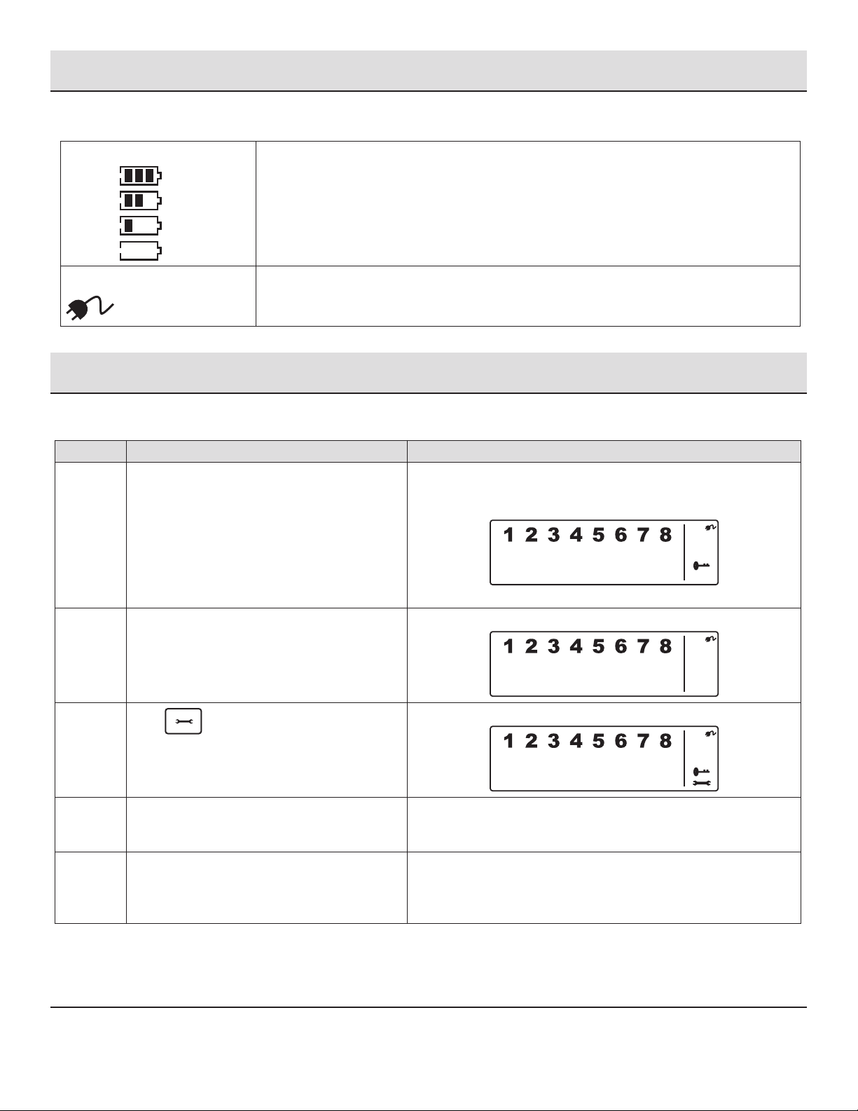
□Install two AAA batteries (not included) into the door/
window sensor.
□Install one 9V battery (not included) into the motion
sensor.
□The smart panel is supplied with a demonstration
switch to show the LCD display panel working, while
the unit is in its packaging. Before powering up the
Smart Panel, remove the wire for this switch by
unscrewing the battery compartment and removing
the cover. The demonstration switch wire is in the top
right hand corner of the compartment
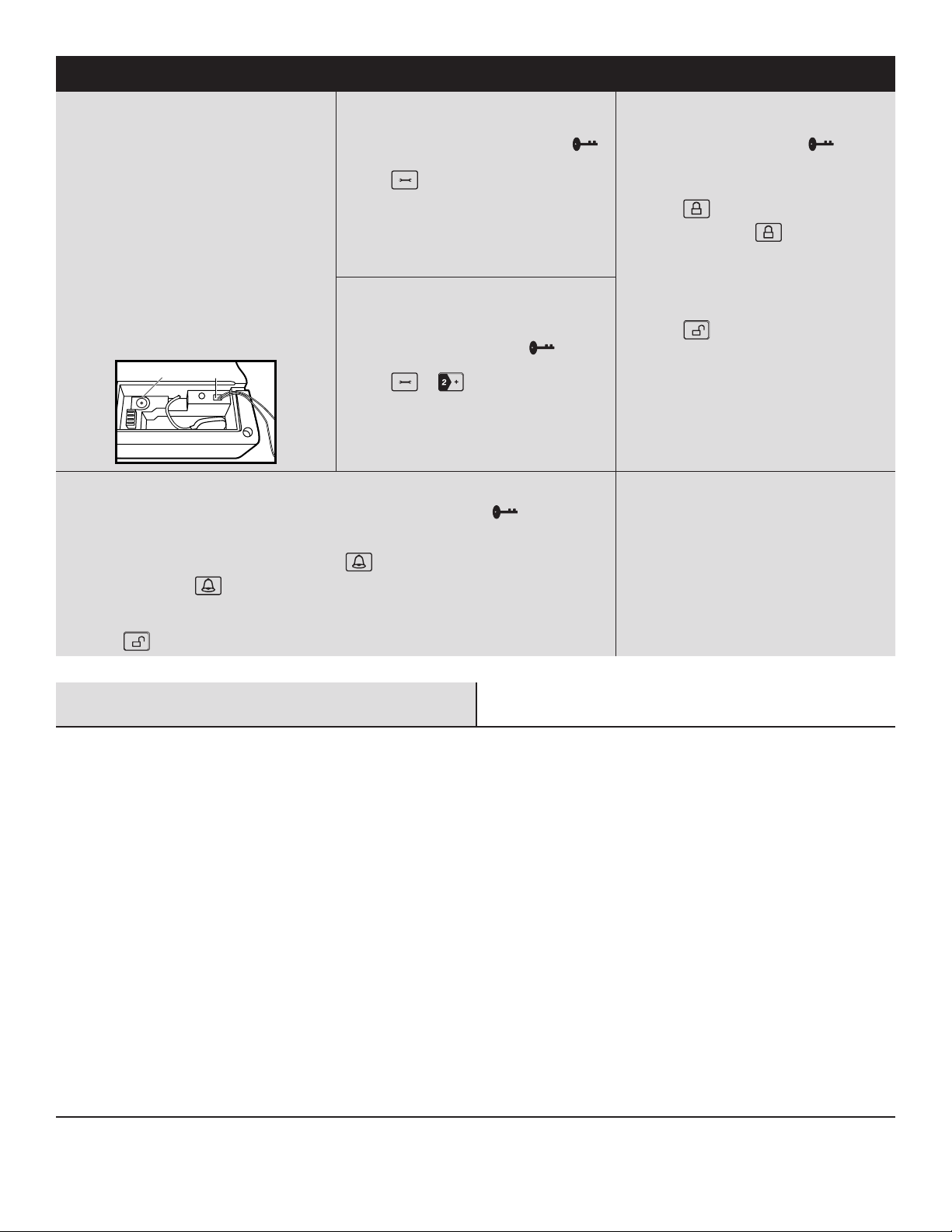
□Unplug the demonstration switch wire (1) and discard
it. Insert a new 9V battery (not included) and plug in
the AC adaptor to the smart panel (2). Replace the
battery compartment cover and screw and plug the
adaptor into a wall socket.
1
2
STEP: 2 SETTING YOUR PIN
a. Ensure you are in STANDBY mode by entering the default
PIN of 1 2 3 4 and pressing the Enter button. The
symbol in the display disappears.
b. Press and 1to set the new PIN.
c. Enter your new 4-digit PIN and press Enter.
d. Re-enter your PIN and press Enter to conrm.
STEP: 4 OPERATING IN ARM MODE
a. Ensure you are in STANDBY mode by entering your 4-digit
PIN and pressing the Enter button. The symbol in
the display disappears.
b. Arm the system:
□Smart Panel: Enter your 4-digit PIN, press Enter, and
press to activate ARM mode.
□Remote Control: Press to activate ARM mode.
c. The default delay is 20 seconds before the system is
armed.
d. Disarm the system:
□Enter your 4-digit PIN and press Enter to disarm the
system.
□Press on the remote control to leave ARM mode.
The default entry delay time is 30 seconds before the
siren is activated.
STEP: 3 ENROLLING THE KEY FOB REMOTE
CONTROL
a. Ensure you are in STANDBY mode by entering your 4-digit
PIN and pressing the Enter button. The symbol in
the display disappears.
b. Press and to enter Remote Control Enroll
Mode.
c. Press any key on the remote control and press Enter to
complete the enrollment.
STEP: 5 OPERATING IN ALERT MODE
a. Ensure you are in STANDBY mode by entering your 4-digit PIN and pressing the Enter button. The symbol in the
display disappears.
b. Enter ALERT mode:
□Smart Panel: Enter your 4-digit PIN, press Enter, and press to activate ALERT mode.
□Remote Control: Press to activate ALERT mode.
c. Exit ALERT mode:
□Enter your 4-digit PIN and press Enter to exit ALERT mode.
□Press on the remote control to leave ALERT mode.
STEP: 6 MUTING THE AUDIBLE COUNTDOWN
□When the Smart Panel is Armed the audible countdown
(beeper) can be silenced by pressing the MUTE button,
during the countdown. To reactivate the audible
countdown (beeper), press MUTE again.
Table of Contents
Table Of Contents ...................................2
Safety Information ..................................3
Warranty ..........................................4
Pre-Installation.....................................4
Planning Installation ...............................4
About Wireless Equipment ...........................4
Specications ....................................5
Package Contents .................................5
Installation ........................................6
Programming Your PIN Number .......................7
Using The Panic Alarm ...............................8
Operating In Standby Mode ...........................8
Operating In Arm Mode ..............................8
Adjusting Exit Delay ................................9
Adjusting Entry Delay...............................9
Adjusting The Alarm Duration .......................10
Muting The Audible Countdown ......................10
Arming The System ...............................10
Disarming The System.............................11
Zone Settings....................................11
Entering Alert Mode ...............................12
Operating in Alert Mode .............................12
Entering Alert Mode ...............................12
Exiting Alert Mode ................................13
Zone Settingg....................................13
Operating in Home Mode ............................14
Entering Home Mode ..............................14
Exiting Home Mode ...............................14
Zone Settingg....................................14
Installing The Sensors ..............................15
Installing The Door/Window Sensor...................15
Installing The Motion Sensor ........................16
Using The Key Fob Remote Control ....................17
Powering Up The Key Fob Remote Control .............17
Adding The Remote Control To The Smart Panel System...17
Operating The Key Fob Remote Control ................18
Deleting A Remote Control From The Smart Panel .......18
Querying The Id Number Of A Remote Control...........19
Home Security Code Settings.........................19
Zone Code Settings.................................20
Faqs.............................................20
Troubleshooting ...................................20

3 HOMEDEPOT.COM
Please contact 844-212-0200 for further assistance.
Safety Information
Retain this manual for future reference.
Even the most advanced alarm systems cannot guarantee 100%
protection against burglary or environmental problems. All alarm
systems are subject to possible compromise or failure-to-warn for a
variety of reasons.
You may encounter problems with your system if:
□The siren is not placed within hearing range or is in a remote
part of the premises.
□The sensors are placed behind doors or other obstacles.
□Intruders gain access through unprotected points of entry
(where sensors are not located).
□Intruders have the technical means of bypassing, jamming, or
disconnecting all or part of the system.
□The power to the sensors is inadequate or disconnected.
□The sensors are not located in acceptable operating areas e.g.
too close to a heat source.
Inadequate maintenance is the most common cause of alarm failure.
Therefore, test your system at least once per week ensure the
sensors and siren(s) are working properly.
Although having an alarm system may make you eligible for reduced
insurance premiums, the system is no substitute for insurance.
WARNING: Security system devices cannot compensate
for loss of life or property.
WARNING: FOR INDOOR USE ONLY. RISK OF PERSONAL
INJURY. PROLONGED EXPOSURE TO ALARM SIREN MAY
CAUSE PERMANENT HEARING LOSS. THIS PRODUCT CANNOT
BE LINKED TO A MONITORED SECURITY SYSTEM. THE
SECURITY FEATURE IS EXCLUSIVELY THE 120DB ALARM
SOUND. DEFIANT IS NOT RESPONSIBLE OR LIABLE FOR ANY
DAMAGE, VANDALISM, THEFT OR OTHER ACTIONS THAT MAY
OCCUR WHILE THIS PRODUCT IS IN USE.
WARNING: Any battery may leak harmful chemicals
which may damage skin, clothing or the inside of the alarm.
TO AVOID RISK OF INJURY, DO NOT LET ANY MATERIAL
LEAKED FROM A BATTERY COME IN CONTACT WITH EYES
OR SKIN. Any battery may rupture or explode if put in a re
or otherwise exposed to excessive heat. TO AVOID RISK OF
INJURY, DO NOT EXPOSE BATTERIES TO EXCESSIVE HEAT.
To reduce the risk of personal injury or harm to your alarm,
take the following precautions:
□Do not use different brands of batteries in the
same alarm
□When replacing batteries always replace the
whole set
□Do not use rechargeable or reusable batteries
□Do not allow children to install batteries
unsupervised
□Follow battery manufacturer’s instructions as to
proper handling, storage and disposal of batteries
CAUTION: The 9V battery in the Smart Panel is for power
back-up purposes only, and the unit should be supplied with
main power (through the AC adaptor) at all times. Difculty
in disarming the Smart Panel in ALARM mode may occur
when it is powered by the back-up battery alone. This is not
a malfunction, and can be resolved by the use of a fresh 9V
battery and main power supplied through the AC adaptor
included.
CAUTION: Take care to insert the batteries with the
correct polarity as shown inside the battery compartments.
CAUTION: At the end of their useful life the batteries
should be disposed of via a suitable Recycling Center. Do
not dispose of with your normal household waste. DO NOT
BURN.
IMPORTANT: Due to the strong signal of the alarm, we
advise that you change the House Security Code settings if
you suspect that one of your in-range neighbors may also
be using this type of alarm system.
LIMITATIONS OF ALARM PRODUCTS
Test product regularly to ensure it functions in accordance with these instructions. The manufacturer is not providing insurance or any
guarantee that the risk of burglary or robbery will be reduced or prevented even if this product is used properly. The manufacturer
recommends that users obtain proper insurance coverage for these risks. The manufacturer does not represent or warrant that that this
product may not be compromised or circumvented, that it will provide proper or adequate warning, or that the use of this product will
prevent injury, property damage or other losses. Note that this product may be bypassed, compromised, fail or fail to warn like any alarm,
including due to improper installation, positioning, or maintenance; tampering; dead, faulty, or improperly installed batteries; sensing
limitations and component failures. The product’s functional range may be affected or limited by environmental conditions, radio frequency
interference or other obstructions. Audible alarm signals may be outside of hearing range, muted by doors, walls, and oors, unheard by
deep sleepers or the hearing-impaired, or overwhelmed by other sounds.

4
Safety Information (continued)
FCC REGULATION
This device complies with Part 15 of the FCC Rules. Operation is subject to the following two
conditions: (1) This device may not cause harmful interference, and (2) This device must accept any interference received, including
interference that may cause undesired operation.
Warning: Changes or modications to this unit not expressly approved by the party responsible for compliance could void the user’s
authority to operate the equipment.
NOTE: This equipment has been tested and found to comply with the limits for a Class B digital device, pursuant to Part 15 of the FCC
Rules. These limits are designed to provide reasonable protection against harmful interference in a residential installation. This equipment
generates, uses and can radiate radio frequency energy and, if not installed and used in accordance with the instructions, may cause
harmful interference to radio communications.
However, there is no guarantee that interference will not occur in a particular installation. If this equipment does cause harmful interference
to radio or television reception, which can be determined by turning the equipment off and on, the user is encouraged to try to correct the
interference by one or more of the following measures:
□Reorient or relocate the receiving antenna.
□Increase the separation between the equipment and receiver.
□Connect the equipment into an outlet on a circuit different from that to which the receiver is connected.
□Consult the dealer or an experienced radio/TV technician for help.
Warranty
1 YEAR LIMITED WARRANTY
This product is guaranteed to be free of defects in materials and workmanship for 1 year from the date of purchase. If this product is
defective, call 1-866-308-3976 for repair or replacement parts or return the product to the store from which it was purchased.
Guarantee does not include normal wear and tear, bulbs or batteries.
Contact the Customer Service Team or visit www.HOMEDEPOT.COM.
Pre-Installation
PLANNING INSTALLATION
Compare all parts in the package with the Package Contents list. If any part appears missing or damaged, do not install this product.
Contact Customer Support.
ABOUT WIRELESS EQUIPMENT
Wireless systems are reliable and tested to high standards; however, it is important to consider that there are some limitations due to their
transmitting power and range:
□Receivers may be blocked by radio signals occurring on or near operating frequencies, regardless of the code selected.
□A receiver can only respond to one transmitted signal at a time.
□Wireless equipment should be tested regularly to determine whether there are sources of interference and to protect against faults.
INSTALLATION LOCATION
Determine the location of the Smart Panel, which should be placed:
□Within a few feet of an electrical outlet
□Where it is easily accessible
□Away from doors or windows that could be accessed by intruders
□Away from extreme temperature sources (radiators, ovens, stoves etc.) and large metal objects that could interfere with the
wireless performance

5 HOMEDEPOT.COM
Please contact 844-212-0200 for further assistance.
Pre-Installation (continued)
SPECIFICATIONS
Smart Panel Motion Sensor
Power Source AC adaptor Power Source 9V alkaline battery
Back-up Power 9V Alkaline Battery RF Working Trans. Freq. 433.92MHz +/-0.5MHz
Sensor Numbers Unlimited PIR Detection Angle <110 Degree (@9VDC)
House Code 4 Jumpers PIR Detection Range “H”:< 15M(50ft)“M”:<
6M(20ft)“L”:< 4M(13ft)
Operating Frequencies 433.92MHz +/-0.5MHz House Code 4 Jumpers
Siren Output 120 dB (Duration-adjustable) Zone Code Pin header: 8 pin
Wireless Range to Smart Panel <150meters(500ft,open area)
Key Fob Remote Control Door/Window Sensor
Power Source 12V Alkaline Battery Power Source 2 AAA Alkaline Batteries, 1.5 V
RF Working Trans. Freq. 433.92MHz +/-0.5MHz RF Working Trans. Freq. 433.92MHz +/-0.5MHz
House Code 4 Jumpers House Code 4 Jumpers
Wireless Range to Smart Panel < 65 meters (215 ft. open area) Zone Code Pin header: 8 pin
Wireless Range to Smart Panel <150 meters (500 ft. open area)
PACKAGE CONTENTS
E
AD
H
G
F
B
C
Part Description Quantity Part Description Quantity
A Smart Panel 1 E AC adaptor for Smart Panel 1
B Key fob remote control 1 F Double-sided adhesive 2
C Door/window sensors 2 G Hardware bag (includes screws,
wall plugs, tamperproof magnet, and
double-sided adhesive)
1
D Motion sensor 1 H Motion sensor mounting bracket
(includes mounting template)
1

6
Installation
1 Wall mounting the smart panel and
tamperproof switch
□First cut out the mounting template for the Smart Panel
along with the area which is marked out for the position of
the tamperproof magnet (see below).
□Tape the template onto the wall, in the position you wish to
install the Smart Panel.
□Using a pencil, mark on the wall the points for drilling holes
for the wall plugs and mounting screws, and the position
for mounting the tamperproof magnet.
□Drill the holes, insert wall plugs and locate the mounting
screws for the Smart Panel.
□Ensure the mounting surface for the tamperproof magnet
is clean.
□Peel back one layer of the protective lm on the double-
sided adhesive strip and attach it to the magnet.
□Peel back the remaining layer of protective lm and press
the magnet rmly in the marked position against the
mounting surface until rmly attached.
□Mount the Smart Panel onto the wall.
□Once the Smart Panel is installed, power up the system.
The tamperproof system is enabled once the Smart Panel
is switched to HOME, ALERT or ARM mode.
2 Powering up the Smart Panel
controller
NOTE: The Smart Panel is supplied with a demonstration
switch to show the LCD display panel working while the unit
is in its packaging. Before powering up the Smart Panel,
remove the wire for this switch as described below.
NOTE: The main power supply (with AC adaptor) must be
plugged in at all times, with the 9V battery functioning as a
back-up power supply only, when the main power supply is
interrupted.
□Unscrew the battery compartment and remove the cover.
□Remove and discard the LED demo socket, if tted.
□Insert a new back-up battery (noting the polarity) and
plug the AC adaptor into the Smart Panel. One beep
will sound and the backlight will blink within 1 second
(Yellow—Red—Green—Yellow). The Smart Panel will
display this image:
□The Smart Panel enters STANDBY mode after the automatic
self-checking completes.
□When the key symbol appears on the LDC screen,
enter 1 2 3 4 (default 4-digit PIN).
□Replace the cover and screw, and connect the AC adaptor
to a wall socket.
84mm
43mm
16mm
36mm
..
A r e a f o r p o s i t i o n i n g
t a m p e r p r o o f m a g n e t
Mount tamperproof magnet here
Fig. 1 Fig. 2
Fig. 4Fig. 3

7 HOMEDEPOT.COM
Please contact 844-212-0200 for further assistance.
Installation (continued)
UNDERSTANDING THE BATTERY AND AC ADAPTOR ICON
Battery Icons:
Full -
High -
Middle
-
Low -
Battery icon shows when the AC power supply is unplugged or interrupted.
9V battery functions as BACK-UP only and the Low symbol means LOW BATTERY.
The LCD backlight ashes YELLOW for 30 seconds and the Low battery icon will blink until the new
battery is replaced or the main power supply (with AC adaptor) is plugged in.
AC Adaptor Icon When the AC adaptor to the Smart Panel is connected to a wall socket, the AC adaptor icon
appears. The backlight will be ON for 10 seconds while the AC adaptor connects to the power
supply.
Programming your PIN Number
The Wireless Home Protection Smart Panel is supplied with a default PIN of “1234”. This can be changed to your own personalized PIN, or
you can change your PIN, as follows:
Step Procedure Example
1 Ensure you are in STANDBY mode by entering the
default PIN of 1 2 3 4 and pressing the Enter
button.
The Smart Panel displays this image when in STANDY mode. One beep
indicates that you entered a valid PIN. Three beeps indicate that an
invalid operation was performed.
2 Enter the default PIN of 1 2 3 4. Press the Enter
button.
The Smart Panel displays this image:
3
Press followed by the 1 button to set the
new PIN.
The Smart Panel displays this image:
4 When the LCD display ashes with a “1”, enter
your new 4-digit PIN and press the Enter button
to conrm.
5 When the LCD display ashes with a “2”, re-enter
your new 4-digit PIN and press the Enter button
to conrm. One beep indicates a valid PIN. Two
beeps indicate an invalid PIN.

8
Using the Panic Alarm
Pressing the and buttons at the same time on either the keypad or the key remote control will immediately transmit an alarm
signal to the Smart Panel, activating the siren, and transmitting an alarm signal to any optional response devices (Auto Dialer, Outdoor Bell
Box & GSM Device), to request emergency assistance.
To disarm the Panic alarm:
□On the Smart Panel: Enter your 4-digit PIN followed by the Enter button to exit from the Panic alarm.
□On the Key Fob Remote Control: Press to exit from the Panic alarm.
USING THE PANIC ALARM WITHOUT ACTIVATING THE SIREN
If you are forced to disarm the system, enter the Duress Password to stop the siren from sounding. The Smart Panel will then silently
transmit an alarm signal to the optional response devices (Auto Dialer, Outdoor Bell Box & GSM Device) to request emergency assistance.
Duress Password:
□Enter the default 4-digit PIN 1 2 3 4, followed by 1 and Enter, or
□Enter your personalized 4-digit PIN, followed by 1 and Enter.
Operating in Standby Mode
If in STANDBY mode, the Smart Panel is prepared for mode selection. You must be in STANDBY mode before turning to ARM mode. To ensure
you are in STANDBY mode:
□Enter the default PIN of 1 2 3 4 or your new 4-digit PIN and press the Enter button. The Smart Panel displays this image when in
STANDY mode. One beep indicates that you entered a valid PIN, three beeps indicate that an invalid operation was performed.
Operating in ARM Mode
When in ARM mode ( ), the Smart Panel siren sounds and the Smart Panel ashes RED every 1.5 seconds when the system is
triggered.
ARM Mode Default Setting
Sensor Zone Status (MODE)
Door/Window Sensor 1 ARM
Door/Window Sensor 2 ARM
Motion Sensor 8 ARM

9 HOMEDEPOT.COM
Please contact 844-212-0200 for further assistance.
Operating in ARM Mode (continued)
ADJUSTING EXIT DELAY
Step Procedure Example
1 Ensure you are in STANDBY mode by entering the
default PIN of 1 2 3 4 OR your new 4-digit PIN and
pressing the Enter button.
The Smart Panel displays this image when in STANDY mode. One beep
indicates that you entered a valid PIN. Three beeps indicate that an
invalid operation was performed.
2 Enter the default PIN of 1 2 3 4 OR your new 4-digit
PIN of your choosing. Press the Enter button.
The Smart Panel displays this image:
3
Press and (as many times as
required) to set the new Exit Delay.
When is pressed the rst time the Smart Panel ashes with the
number of seconds currently set for the Exit Delay. The factory default
setting is 20 seconds. Each time this button is pressed, the Exit Delay
is increased by an additional 10 seconds between the adjustable range
of 10 to 60 seconds. The Exit Delay time on the LCD display will ash
until the setting is completed.
4 Press the Enter button to conrm the setting and
return the Smart Panel to STANDBY.
ADJUSTING ENTRY DELAY
Step Procedure Example
1 Ensure you are in STANDBY mode by entering the
default PIN of 1 2 3 4 OR your new 4-digit PIN and
pressing the Enter button.
The Smart Panel displays this image when in STANDY mode. One beep
indicates that you entered a valid PIN. Three beeps indicate that an
invalid operation was performed.
2 Enter the default PIN of 1 2 3 4 OR your new 4-digit
PIN of your choosing. Press the Enter button.
The Smart Panel displays this image:
3
Press and (as many times as
required) to set the new Entry Delay.
When is pressed the rst time, the Smart Panel ashes with
the number of seconds currently set for the Entry Delay. The factory
default setting is 30 seconds. Each time this button is pressed, the Exit
Delay is increased by an additional 10 seconds between the adjustable
range of 10 to 60 seconds. The Exit Delay time on the LCD display will
ash until the setting is completed.
4 Press the Enter button to conrm the setting and
return the Smart Panel to STANDBY.

10
Operating in ARM Mode (continued)
ADJUSTING THE ALARM DURATION
Step Procedure Example
1 Ensure you are in STANDBY mode by entering
the default PIN of 1 2 3 4 OR your new 4-digit
PIN and pressing the Enter button.
The Smart Panel displays this image when in STANDY mode. One beep
indicates that you entered a valid PIN. Three beeps indicate that an invalid
operation was performed.
2 Enter the default PIN of 1 2 3 4 OR your new
4-digit PIN of your choosing. Press the Enter
button.
The Smart Panel displays this image:
3
Press and (as many times as
required) to set the new Alarm Duration.
When is pressed the rst time, the Smart Panel ashes with
the number of minutes currently set for the Alarm Duration. The factory
default setting is 1 minute. Each time this button is pressed, the alarm
duration is increased by a further minute up to the maximum of 6
minutes. The Alarm Duration time on the LCD display will ash until the
setting is completed.
4 Press the Enter button to conrm the setting
and return the Smart Panel to STANDBY.
MUTING THE AUDIBLE COUNTDOWN
When the Smart Panel is ARMED, the audible countdown (beeper) can be silenced by pressing the MUTE button during the countdown. To
reactivate the audible countdown (beeper) press the MUTE button again.
ARMING THE SYSTEM
On the Key Fob Remote Control: Press to ARM the system.
On the Smart Panel: First make sure the Smart Panel is in STANDBY mode, and then ARM the system by completing these steps:
Step Procedure Example
1 Ensure you are in STANDBY mode by entering
the default PIN of 1 2 3 4 OR your new 4-digit
PIN and pressing the Enter button.
The Smart Panel displays this image when in STANDY mode. One beep
indicates that you entered a valid PIN. Three beeps indicate that an invalid
operation was performed.
2 Enter your 4-digit PIN, press the Enter button,
and press for ARM mode.
There is a 20 second exit delay time with a visual and audible (beeping)
countdown before the system is armed. Press MUTE to disable the beeping
countdown. Press MUTE again to resume the beeping.
If the Zone is enabled, a number appears as displayed:
The system will then enter ARM mode after 20 seconds.

11 HOMEDEPOT.COM
Please contact 844-212-0200 for further assistance.
Operating in ARM Mode (continued)
When in ARM mode, the Smart Panel ashes RED every 5 seconds, acting as a deterrent to potential intruders. However, if an intruder is
detected the panel continuously and rapidly ashes RED.
Once an intrusion has occurred (with the zone triggered under ARM status), the alarm siren sounds and the Smart Panel ashes RED every
1.5 seconds and indicates the triggered zone. After the initial triggering, the alarm will immediately sound, without delay, if any other
sensors are triggered.
DISARMING THE SYSTEM
On the Smart Phone Panel: Enter your 4-digit PIN and press Enter to disarm the system.
On the Key Fob Remote Control: Press to disarm the system.
ZONE SETTINGS
Step Procedure Example
1 Ensure you are in STANDBY mode by entering the
default PIN of 1 2 3 4 OR your new 4-digit PIN and
pressing the Enter button.
The Smart Panel displays this image when in STANDY mode. One beep
indicates that you entered a valid PIN. Three beeps indicate that an
invalid operation was performed.
2 Enter the default PIN of 1 2 3 4 OR your new 4-digit
PIN. Press the Enter button.
The Smart Panel displays this image:
3
Press and to set the ARM mode.
Toggle 1 2 3 4 5 6 7 8 to turn each zone ON or OFF. If no number
appears, the zone is turned OFF. The Smart Panel displays this image:
4 Press the Enter button to conrm the setting and
return the Smart Panel to STANDBY.
TRIGGERS IN ARM MODE
Example: Zone 1 Trigger
Step Procedure Example
1Under ARM mode Smart Panel displays this image:
2System Trigger One beep indicates the system is triggered.

12
Operating in Standby Mode (continued)
3 Entry delay 30 seconds There are 30 seconds of entry delay time with a visual countdown for
disarming. Once an intrusion has occurred (zone triggered under ARM
status), the alarm siren sounds for 1 minute and the Smart Panel ashes
RED every 1.5 seconds with the triggered zone indicated, until the system is
disarmed.
To disarm the system, enter the 4-Digit PIN or press on the remote
control.
4 Return to ARM mode after the initial triggering After the initial triggering, the alarm will immediately sound, without delay, if
any other sensors are triggered.
Operating in Alert Alert Mode
In Alert mode ( ), the Smart Panel chime sounds and the Smart Panel ashes GREEN every 1.5 seconds and indicates the triggered
zone, when the system detects a visitor in the protected area.
ALERT Mode Default Setting:
Sensor Zone Status (MODE)
Door/Window Sensor 1 ALERT
Door/Window Sensor 2 ALERT
Motion Sensor 8 ALERT
ENTERING ALERT MODE
On the Key Fob Remote: Press to activate.
On the Smart Panel: First make sure the Smart Panel is in STANDBY mode, and then enter into ALERT mode following these steps:
Step Procedure Example
1 Ensure you are in STANDBY mode by entering
the default PIN of 1 2 3 4 OR your new 4-digit
PIN and pressing the Enter button.
The Smart Panel displays this image when in STANDY mode. One beep
indicates that you entered a valid PIN. Three beeps indicate that an invalid
operation was performed.
2 Enter your 4-digit PIN, press the Enter button,
and for ALERT mode.
The system enters ALERT mode. If the Zone is enabled, a number appears
as displayed in this image:

13 HOMEDEPOT.COM
Please contact 844-212-0200 for further assistance.
Operating in Alert Alert Mode (continued)
EXITING ALERT MODE
On the Smart Panel: Enter your 4-digit PIN followed by Enter to exit ALERT mode.
On the Key Fob Remote Control: Press to exit ALERT mode.
ZONE SETTINGS
Programming each zone in ALERT mode:
Step Procedure Example
1 Ensure you are in STANDBY mode by entering the
default PIN of 1 2 3 4 OR your new 4-digit PIN and
pressing the Enter button.
The Smart Panel displays this image when in STANDY mode. One
beep indicates that you entered a valid PIN. Three beeps indicate
that an invalid operation was performed.
2 Enter your 4-digit PIN and press the Enter button. The Smart Phone Panel displays this image:
3
Press the Enter button and to set ALERT
mode.
Toggle 1 2 3 4 5 6 7 8 to turn each zone ON or OFF. If no number
appears, the zone is turned OFF.
The Smart Panel displays this image:
4 Press the Enter button to conrm the setting and
return the Smart Panel to STANDBY.

14
Operating in Home Mode
There are default settings that allow the system to operate after opening the package. These settings can be adjusted to suit your individual
requirements. The HOME mode ( ) allows the system to operate in both ARM and ALERT modes in different zones.
HOME mode default setting:
Sensor Zone Status (MODE)
Door/Window Sensor 1 ALERT
Door/Window Sensor 2 ALERT
Motion Sensor 8 ARM
ENTERING HOME MODE
On the Key Fob Remote Control: Press to activate.
On the Smart Panel: Ensure the Smart Panel is in STANDBY mode, and then enter HOME mode by completing these steps:
Step Procedure Example
1 Ensure you are in STANDBY mode by entering the
default PIN of 1 2 3 4 OR your new 4-digit PIN and
pressing the Enter button.
The Smart Panel displays this image when in STANDY mode.
One beep indicates that you entered a valid PIN. Three beeps
indicate that an invalid operation was performed.
2
Enter your 4-digit PIN, press Enter, and to enter
HOME mode.
If the Zone is enabled, a number appears as displayed here:
EXITING HOME MODE
On the Smart Phone Panel: Enter your 4-digit PIN followed by the Enter button to exit HOME mode.
On the Key Fob Remote Control: Press to exit HOME mode.
ZONE SETTINGS
Programming each zone in HOME mode:
Step Procedure Example
1 Ensure you are in STANDBY mode by entering the
default PIN of 1 2 3 4 OR your new 4-digit PIN and
pressing the Enter button.
The Smart Panel displays this image when in STANDY mode. One
beep indicates that you entered a valid PIN. Three beeps indicate
that an invalid operation was performed.
2 Enter the 4-digit PIN followed by the Enter button. The Smart Panel displays this image:

15 HOMEDEPOT.COM
Please contact 844-212-0200 for further assistance.
Operating in Home Mode (continued)
3
Press and to enter HOME mode.
Toggle 1 2 3 4 5 6 7 8 to turn each zone in different mode:
indicates ALERT mode for a zone
indicates ARM mode for a zone
indicates the zone is turned OFF and the number will not appear
The Smart Panel displays this image:
4 Press the Enter button to conrm the setting and
return the Smart Panel to STANDBY.
Installing the Sensors
This package includes 3 wireless sensors which have a pre-programmed default setting that begins working immediately once the battery
is activated (the Key Fob Remote Control needs to be enrolled onto the system before it can operate). It is advisable to install the main
package rst and then personalize the settings once the system is functioning properly. This section should help you to change the system
settings in order to create a more personal home environment.
First, determine the location of the sensors. Place the sensors where they are not easily accessible, in the most vulnerable rooms or near
key entry points, away from extreme temperature sources (radiators, ovens, stoves etc.) and large metal objects that could interfere with
the wireless performance, and where better RF performance can be achieved (if necessary).
Once you have selected a location for the sensors, the system can be powered up.
INSTALLING THE DOOR/WINDOW SENSOR
The Door/Window Sensor consists of two parts, a transmitter and a magnet. Once this sensor is installed, and the two parts are fastened
onto the door or window, the sensor will trigger and transmit a message to the Smart Panel when the door or window is opened. One Door/
Window Sensor is pre-programmed in Zone 1 and the other one is set in Zone 2. However, these settings can be adjusted according to your
requirements.
Step 1: Powering up the Door/Window Sensor
Remove the battery cover; insert new batteries noting the polarity as shown in the diagram below and
replace the cover. This sensor requires 2 x AAA batteries.
Low battery indication: If the batteries need to be replaced, the RED LED on the transmitter will ash
slowly.
Step 2: Installing the Door/Window Sensor
□Mount the transmitter on a xed surface such as a door or a window frame.
□Mount the magnet on a movable surface such as a door or a window.
□Ensure the >/< marks on the sides of the transmitter and magnet match up as shown in the diagram.
The transmitter and the magnet must be no more than 5 mm (0.2 in.) apart.
Step 3: Mounting with the Double-sided Adhesive Pad
□Ensure the mounting surface is clean.
□Peel back one layer of the protective lm and attach it to the transmitter.
□Peel back the remaining layer of protective lm and press the transmitter rmly in place against the mounting surface until rmly attached.
□Repeat to attach the magnet.

16
Installing the Sensors (continued)
INSTALLING THE MOTION SENSOR
The Motion Sensor is designed to sense movement in a given area.
NOTE: It is best if pets are not allowed onto higher surfaces so that the sensors are not triggered unnecessarily (no more than 1 m/3.3 ft.
high).
Step 1: Powering up the Motion Sensor
□Remove the battery cover, insert and connect a 9V battery as shown in diagram below and replace
the cover. (Requires 1 x 9V battery).
Low battery indication: If the batteries need to be replaced, the RED LED will ash (not including entry /
exit delay ashing).
Step 2: Installing the Motion Sensor
Determine the location of the Motion Sensor. The Sensor should be placed:
□In the most vulnerable rooms or near key entry points
□On a solid surface between 1.8 m to 2.4 m (6 ft. to 8 ft.) from the oor
□Away from extreme temperature sources (radiators, ovens, stoves etc.)
□Away from direct sunlight
□Indoors only and not behind partitions
□Where better RF performance can be achieved (if necessary)
Step 3: Adjusting Sensor Sensitivity
NOTE: The Motion Sensor is designed with a built-in sleep timer to save battery power. The Motion Sensor will sleep for 3 minutes after
every trigger. Any movement detected in sleep mode will not be reported, please bear this in mind during system set up.
The sensitivity of the Motion Sensor is adjustable and can be changed by setting the connector, found in the battery compartment, on
either the “High”, “Middle” or “Low” position. When the sensitivity is set to “Low”, more movement is required to trigger the sensor. It is
recommended to set the sensitivity to “Low” and perform a “Walk Test” (see step 4). If the walk test result is satisfactory, the sensitivity
does not require further adjustment. If the walk test result shows the sensitivity is too low, then the sensitivity can be set to “Middle” or
“High” as required. It is recommended that a walk test be conducted after each change in sensitivity setting. Test the Motion Sensor by
pressing the test button inside the battery compartment.
Step 4: Performing a Walk Test
After mounting the sensor at the desired location, it is important to perform a walk test in order to
determine if the sensor is detecting the correct area. The distance at which the sensor can detect motion
can be adjusted by altering the angle of the sensor. To reduce the detection range, move the sensor
downward and move the sensor upward to maximize the range.
NOTE: Enter into ALERT mode before you perform the walk test, so that the alarm is not triggered.
Walk in the area that you would like the sensor to monitor. If movement is detected, the red light inside
the unit will appear. If the red light does not appear, adjust the mounting angle accordingly. Perform the
walk test again after 3 minutes. Repeat this procedure until motion is detected. While carrying out the
test, there should be no movement in the detection area during the 3 minute interval.
Tips: The sensor should not face towards direct sunlight, be placed near heat or cold producing devices
(i.e. air conditioning, radiators, fans, ovens, heaters etc.) that may cause false triggers. Also perform the
walk test in areas which the sensor is not intended to cover, to ensure movement cannot be detected.

17 HOMEDEPOT.COM
Please contact 844-212-0200 for further assistance.
Installing the Sensors (continued)
Step 5: Mounting using Screws
□Hold the enclosed mounting template against the wall at the selected
location and mark the points for drilling.
□Drill the holes and insert wall plugs.
□Attach the bracket to the mounting surface with the screws provided.
□Attach the Motion Sensor to the Mounting bracket by sliding the O-ring
over the round ball on the back of the sensor, then snap the ball into the
mounting bracket and push the O-ring over the bracket to hold it in place.
Using the Key Fob Remote Control
The Wireless Home Protection System Remote Control allows you to operate the system’s Smart Panel remotely, from inside or outside
the property. Using the control, the system can be armed or disarmed and the siren can be activated instantly if required (using the Panic
function).
POWERING UP THE KEY FOB REMOTE CONTROL
The Remote Control includes a 12V alkaline battery. To activate, unscrew and remove the back of the Remote Control, and carefully remove
the clear plastic insulation tab from the battery. If the battery is dislodged, replace it noting the correct polarity as shown inside the battery
compartment. Replace the battery cover.
ADDING THE REMOTE CONTROL TO THE SMART PANEL SYSTEM
Before you can use the Key Fob Remote Control supplied with the system, or any additional Remote Controls, they rst need to be enrolled
(added onto the system) as follows:
Step Procedure Example
1 Ensure you are in STANDBY mode by entering the
default PIN of 1 2 3 4 OR your new 4-digit PIN and
pressing the Enter button.
The Smart Panel displays this image when in STANDY mode. One
beep indicates that you entered a valid PIN. Three beeps indicate
that an invalid operation was performed.
2 Enter the 4-digit PIN followed by pressing the Enter
button.
The Smart Panel displays this image:
3
Press and to enter the Remote Control
Enroll mode. Then press any key on the new Remote
Control to enroll it onto the system.
The LCD display ashes the ID number of the remote to be
enrolled. For example, when enrolling the rst remote ID no. “01”
will ash. Once the rst remote is enrolled the “02” will ash
ready for a second remote to be enrolled. One beep indicates that
the remote was enrolled to the Smart Panel successfully.
It is recommended that the ID No. is marked on the remote in case
it needs to be deleted at a later stage.
4 Press the Enter button to conrm the enrollment and
return the Smart Panel to STANDBY.

18
Using the Key Fob Remote Control (continued)
OPERATING THE KEY FOB REMOTE CONTROL
The remote can be used to arm, disarm, and operate the system instantly.
□ARM – Arms the system, triggering the preset exit delay. When triggered, the Smart
Panel’s LED light will ash Red and indicate the triggered zone.
□DISARM – Disarms the system instantly and the system will return to Standby mode.
□ALERT – Puts the system into Alert mode and a chime will sound if any of the sensors
are triggered. The Green light on the Smart Panel LED display will ash and indicate the
triggered zone.
□HOME – Sets the system in Home mode which will operate the system in both Arm and
Alert modes in different preset zones.
□PANIC – If the HOME and ALERT buttons are pressed together the systems alarm is
immediately activated
DELETING A REMOTE CONTROL FROM THE SMART PANEL
If a Remote Control device is damaged or lost, it can be deleted from the system as follows:
Step Procedure Example
1 Ensure you are in STANDBY mode by entering the
default PIN of 1 2 3 4 OR your new 4-digit PIN and
pressing the Enter button.
The Smart Panel displays this image when in STANDY mode. One
beep indicates that you entered a valid PIN. Three beeps indicate
that an invalid operation was performed.
2 Enter the 4-digit PIN followed by pressing the Enter
button.
The Smart Panel displays this image:
3
Press and to enter the Remote Control
Deleting mode. Then input the ID number of the
Remote Control you wish to delete from the system.
The LCD display ashes the total number of remotes currently
enrolled to the system. For example, if the Smart Panel has 3
remotes enrolled, the LCD display will ash “03”.
Input the remote ID no. (e.g. “02”) for the remote you wish to
delete (Inputting “00” will delete all remote controls).
The LCD display will then ash the total number of remotes
enrolled after deletion. One beep indicates that the remote was
successfully deleted from the Smart Panel.
4 Press the Enter button to conrm the enrollment and
return the Smart Panel to STANDBY.

19 HOMEDEPOT.COM
Please contact 844-212-0200 for further assistance.
Using the Key Fob Remote Control (continued)
QUERYING THE ID NUMBER OF A REMOTE CONTROL
The ID number of a Remote Control device can be identied as follows:
Step Procedure Example
1 Ensure you are in STANDBY mode by entering the
default PIN of 1 2 3 4 OR your new 4-digit PIN and
pressing the Enter button.
TThe Smart Panel displays this image when in STANDY mode. One
beep indicates that you entered a valid PIN. Three beeps indicate
that an invalid operation was performed.
2 Enter the 4-digit PIN followed by pressing the Enter
button.
The Smart Panel displays this image:
3
Press and to go into Remote Querying
mode, and then press any key on the remote to
check its ID.
After entering into Remote Querying mode, the LCD display will
ash the total number of remote controls currently enrolled to the
system. For example, if 3 remotes are enrolled, the LCD display will
ash “03”.
The ID number of the Remote can then be checked by pressing any
key on the remote. For example, if the LCD display ashes “02”
then that is the ID of the remote.
4 Press the Enter button to complete the query and
return the Smart Panel to STANDBY mode.
Home Security Code Settings
In most cases the factory settings of the House Security Code will NOT need to be changed. However, if the Smart Panel and Sensors
activate intermittently or do not work at all, this may be due to interference with other systems, which can be avoided by changing the
House Security Code. To change this code, complete these steps with each system module:
1. There are four Jumpers/Dip-switches on each device. To locate these, remove the battery compartment cover.
2. Set the Jumpers as shown below (ON - Push in / OFF - Pull out) to change the House Security Code setting. Make sure the Jumpers on
the Smart Panel and its Sensors exactly match each other AND the Dip-switch setting on the Key Fob Remote Control.
Jumpers for House Security Code Smart Panel
- Each sensor
Default House Security Code:
1: ON, 2: ON, 3: ON, 4: ON
*Jumper: ON = Pushed in, OFF = Pulled out
Dip-switches for House Security Code Key Fob Remote Control
Default House Security:
1: ON, 2: ON, 3: ON, 4: ON

20
Zone Code Settings
Sensors are supplied with pre-assigned Zone settings to make setup easy – the Door/Window Sensors are pre-assigned to Zones 1 & 2 and the Motion
Sensor to Zone 8.
To assign a Sensor to a different zone, change the Zone Code on the Sensor by completing these steps:
1. Remove the Jumper compartment cover to access the Zone Code Jumper on each Sensor.
2. Pull out the Jumper and reassign it to the new Zone (Zones 1 to 8) as shown in the diagram below.
3. Replace Jumper compartment cover.
Jumper for Zone Code
Default zone code:
Door/Window sensor – Zone 1
Door/Window sensor – Zone 2
Motion sensor – Zone 8
FAQs
Q.1: What is the best way to set up my system? Where should I put my Smart Panel and the sensors?
We recommend that you take some time in advance to think about the placement of the Smart Panel and Sensors. The best location for the Smart Panel is by the main entry/exit
point, in a hallway, or in another central location in your home. However, it must be plugged into a power socket, which may dictate where it can be placed.
Please note that the alarm is pre-programmed with default settings, allowing you a pre-determined amount of time to enter (30 seconds) and time to exit (20 seconds) before the
alarm sounds. You can either change the default setting to allow more time to enter/exit your home or, alternatively use the Key Fob to disarm the system.
Q.2: How many Sensors can the Smart Panel support?
An unlimited number of sensors can be supported by the system, added to different zones in your house, as you see t.
Q.3: What wireless range should I expect from the Sensors?
The range will vary depending on the type of structure. However, in an open space, the sensors should be capable of transmitting a signal up to 150 meters (500 ft.) from the Smart
Panel. Determine the location of the sensors rst and change to a different location for better RF performance.
Q.4: How do I attach my Sensors?
Adhesive tape and screws are provided for the purpose of securely mounting these items. Please refer to the user guide for more information about mounting the Smart Panel and
the wireless sensors.
Q.5: Do I have to program the Smart Panel?
The Wireless Home Protection System WP-100 is designed for easy installation. This means that the wireless sensors are in a default setting already registered to the Smart Panel
and will therefore function immediately after the sensors are powered up. If you choose to buy additional accessories, these will need to be added to your system using the easy to
follow instructions.
Due to the strong signal of the alarm, we advise that you change the House Security Code settings following the instructions in this manual, if you suspect that one of your in-range
neighbors may also be using this alarm system.
Q.6: Can I still use the same system if I move?
The Wireless Home Protection System WP-100 is completely portable. If you move, you can remove your Smart Panel and wireless accessories and re-install them in your new
property.
Q.7: What if I forget my PIN?
If you forget your PIN, you may press the Reset button inside the battery compartment of the Smart Panel and the PIN will be reset to the factory default PIN 1234.
Q.8: Why does my Motion Sensor not respond to movement?
Motion Sensors are very sensitive. To preserve battery life the Sensor will go to “Sleep” after an event has been identied and reported to the panel. This “Sleep” period lasts 3
minutes, after which, if no activity is detected, the Motion Sensor will again become active and ready to detect other events.
Q.9: Why does my Motion Sensor keep generating false alarms?
If you have a pet, make sure they have not triggered the system. Remember, sensitivity to pets increases in certain circumstances e.g. the nearer the pet to the Sensor.
Troubleshooting
AC POWER FAILURE
This may occur if your security system is accidentally unplugged or if there has been a main power cut. If a full power failure occurs, please contact your
electric company to nd out the source of the problem. The back-up battery will continue to run the system for approximately 6 hours.
SYSTEM BATTERY FAILURE
This may occur if the emergency back-up battery has been drained and needs to be replaced. If AC power is not restored, the low battery symbol will ash
indicating that the Smart Panel back-up battery is running low. The back-up battery should be replaced once the low battery symbol appears.
SENSOR FAILURE
This may occur if a sensor is not communicating with the Smart Panel. It is necessary for you to ensure the House Security Code dipswitch and jumpers of
the sensors are set correctly to the Smart Panel.
Table of contents
Other Defiant Security System manuals