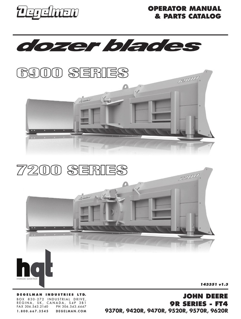
Degelman SILAGE KING User manual

143444 v1.1
FIT-UP & PARTS
MANUAL
DEGELMAN INDUSTRIES LP
BOX 830-272 INDUSTRIAL DRIVE,
REGINA, SK, CANADA, S4P 3B1
FAX 306.543.2140 PH 306.543.4447
1.800.667.3545 DEGELMAN.COM
JOHN DEERE - 9R SERIES
(MY2022+) 9R 390, 440, 490, 540, 590, 640
(FT4 2014-2021) 9370R, 9420R, 9470R, 9520R, 9570R, 9620R
for NANT/NAHT & HANT/HAHT Silage King Models


Record Serial Number:
...........................................................
IMPORTANT:
READ MANUAL
DEGELMAN INDUSTRIES LP
BOX 830-272 INDUSTRIAL DRIVE,
REGINA, SK, CANADA, S4P 3B1
FAX 306.543.2140 PH 306.543.4447
1.800.667.3545 DEGELMAN.COM
QUICK GUIDE INDEX
Introduction 1
Pivot & Main Frame (No-Angle Models) 2
Pivot & Main Frame (Models with Hydraulic Angle) 3
Mounting Brackets - Undercarriage (MY2022+) 4
Mounting Brackets - Undercarriage (FT4 2014-2021) 5
Mounting Brackets - Installation 6
Mounting Brackets - Optional Mounts 8
Hydraulic Routing 10
Hose Bundle/Routing Overview 14
Mounting Procedure 17
Warranty 18
REFERENCE INFORMATION
NANT (No-Angle with No-Tilt Model)
NAHT (No-Angle with Hydraulic Tilt Model)
HANT (Hydraulic Angle with No-Tilt Model)
HAHT (Hydraulic Angle with Hydraulic Tilt Model)

-1-
143444 - Silage King (21-April-2023)
Introduction
Important: Check torque on all
hardware periodically. Check after
first 2, 10, 40, then every 200 hours.
• Torque values listed are for general
use only. If a different torque value
or tightening procedure is specified for a specific
application, do not use these values.
• Refer to the “Parts” section for proper grade and
length of bolts for replacement parts.
• Do not replace locknuts with nuts and lock washers.
Replace all parts with original, specified parts only.
• Dry values shown mean the bolt/nut is plain or zinc
plated without any lubrication.
CHECK HARDWARE TORQUE
TORQUE
all hardware
Unless otherwise stated:
Hardware - Hex, GR5 UNC (imperial) or P8.8 (metric)
Hoses - 3/8, ends come with 3/4 JIC female swivel.
The tables below give correct torque values for various
bolts and capscrews. Tighten all bolts to values in
charts unless otherwise noted. Check tightness of bolts
periodically, using torque charts as a guide. Replace
hardware with the same strength (Grade/Class) bolt.
HYDRAULIC FITTING TORQUE
Size lb.ft (N.m)
3/4 75 (100)
7/8 90 (122)
IMPERIAL TORQUE SPECIFICATIONS
(based on “Zinc Plated” values)
Size Grade 5 Grade 8
lb.ft (N.m) lb.ft (N.m)
1/4” 7 (10) 10 (14)
5/16” 15 (20) 20 (28)
3/8” 25 (35) 35 (50)
7/16” 40 (55) 60 (80)
1/2” 65 (90) 90 (120)
9/16” 90 (125) 130 (175)
5/8” 130 (175) 180 (245)
3/4” 230 (310) 320 (435)
7/8” 365 (495) 515 (700)
1” 550 (745) 770 (1050)
1-1/8” 675 (915) 1095 (1485)
1-1/4” 950 (1290) 1545 (2095)
1-3/8” 1250 (1695) 2025 (2745)
1-1/2” 1650 (2245) 2690 (3645)
SAE-5 SAE-8
METRIC TORQUE SPECIFICATIONS
(based on “Zinc Plated” values)
Size Class 8.8 Class 10.9
lb.ft (N.m) lb.ft (N.m)
M6 7 (10) 10 (14)
M8 16 (22) 23 (31)
M10 30 (42) 45 (60)
M12 55 (75) 80 (108)
M14 90 (120) 125 (170)
M16 135 (185) 195 (265)
M18 190 (255) 270 (365)
M20 265 (360) 380 (515)
M22 365 (495) 520 (705)
M24 460 (625) 660 (895)
M27 675 (915) 970 (1315)
M30 915 (1240) 1310 (1780)
M33 1250 (1695) 1785 (2420)
M36 1600 (2175) 2290 (3110)
8.8 10.9
Overview of Silage King Blade Manual (143415)
• Safety
• Operation
• Transport & Storage
• Blade Components / Attachments
• Tilt Bell Assembly
• Blade Tilt Options
• Blade Hydraulic Options
• Fold-Back Overview for Hinge Kit
• Maintenance
• Optional Blade Attach/Detach (NANT & NAHT)
• Troubleshooting
• Warranty
The documentaion for this particular fit-up has been
divided into two manuals:
1) Silage King Blade Components, Operation,
Safety, and Maintenance. (Manual 143415)
2) Tractor Fit-up & Frame Components, Hydraulic
Routing, and Mounting Procedure. (This Manual)
It is strongly recommended that you familiarize
yourself and completely read through both manuals,
have them both available for quick-reference, and
that you review them annually.
MANUAL OVERVIEW HARDWARE TORQUE SETTINGS
-2-
143444 - Silage King (21-April-2023)
Pivot & Main Frame - Silage King Blade Models with No-Angle
795250 - Pivot
Frame Assembly (1)
132051 -Sidewind
Jack (2)
795280 - Main Frame
Assembly (1)
118645 - Bolt, 5/8 x 1-1/4 (2)
118508 - Lock Washer, 5/8 (2)
118514 - Flat Washer, 5/8 F436 (2)
789580 - Pivot Pin,
pivot/main (2)
123213 - Cylinder,
4-1/2 x 20 x 2 (2)
123213 - Cylinder,
4-1/2 x 20 x 2 (2)
780332 - Hose Clamp Block (2)
780333 - Clamp Block Plate (2)
118928 - Bolt, 5/16 x 2-1/4 (2)
118503 - Lock
Washer, 3/8 (2)
118003 - Bolt,
3/8 x 3/4 (2)
795119 -
Tilt Coupler
Bracket (1)
Tilt Option Only
No-Tilt
Option
Only
118767 - Bolt, 7/8 x 3 GR8 (4)
118774 - Flat Washer, 7/8 F436 (8)
117416 - Lock nut, 7/8 GRC Unitorque (4) 575193 - Pin Shaft, 2 x 8-1/2 (2)
575195 - Pin Shaft,
2 x 9-1/4 (2)
575194 - Pin Head (4)
(Upper Pins)
(Lower Pins)
118503 - Lock Washer, 3/8 (2)
118003 - Bolt, 3/8 x 3/4 (2)
117598 - Flat Washer, M8 (2)
117621 - Bolt, M8 x 25 (2)
795326 - Parking Station Bracket (1)
Included with
Hydraulic Coupler
Assembly
(Note: Apply Blue Loctite 242 to M8
Bolt threads when installing)
PIVOT & MAIN FRAME OVERVIEW
PIVOT & MAIN FRAME COMPONENTS

-3-
143444 - Silage King (21-April-2023)
Pivot & Main Frame - Silage King Blade Models with Hydraulic Angle
795600 - Pivot
Frame Assembly (1)
132051 -Sidewind
Jack (2)
795280 - Main Frame
Assembly (1)
118645 - Bolt, 5/8 x 1-1/4 (2)
118508 - Lock Washer, 5/8 (2)
118514 - Flat Washer, 5/8 F436 (2)
789580 - Pivot Pin,
pivot/main (2)
123213 - Cylinder,
4-1/2 x 20 x 2 (2)
123213 - Cylinder,
4-1/2 x 20 x 2 (2)
118767 - Bolt, 7/8 x 3 GR8 (4)
118774 - Flat Washer, 7/8 F436 (16)
117416 - Lock nut, 7/8 GRC Unitorque (8) 575193 - Pin Shaft, 2 x 8-1/2 (2)
575195 - Pin Shaft,
2 x 9-1/4 (6)
575194 - Pin Head (8)
(Upper Lift Pins Only)
(Lower Lift &
Angle Pins)
123227 - Cylinder,
4-1/2 x 16 x 2-1/2 (2)
(Lift Cylinders)
(Angle Cylinders)
780332 - Hose Clamp Block (1)
780333 - Clamp Block Plate (1)
118928 - Bolt, 5/16 x 2-1/4 (1)
(Angle Cylinder Pins Use)
117426 - Bolt, 7/8 x 2-3/4 GR8 (4)
HAHT (Models with Hydraulic Tilt)
118503 - Lock Washer, 3/8 (2)
118003 - Bolt, 3/8 x 3/4 (2)
117598 - Flat Washer, M8 (2)
117621 - Bolt, M8 x 25 (2)
795326 - Parking Station Bracket (1)
Included with
Hydraulic Coupler
Assembly
(Note: Apply Blue Loctite 242 to M8
Bolt threads when installing)
HANT (Models with No-Tilt)
118003 - Bolt, 3/8
x 3/4 (2)
118503 - Lock Washer,
3/8 (2)
141801 - Parking Station (1)
PIVOT & MAIN FRAME OVERVIEW
PIVOT & MAIN FRAME COMPONENTS

-4-
143444 - Silage King (21-April-2023)
UNDERCARRIAGE BRACKET COMPONENTS
*791248 - Shim, 3 hole (4)
118747 - Bolt, M20 x 2.5 x 80 (10)
118750 - Lock Nut,
M20 x 2.5 (10)
117553 -
Bolt, M20 x
2.5 x 70 (5)
(Both sides)
(RH side)
(LH side) 118775 - Flat Washer,
3/4 F436 (20)
118775 - Flat Washer, 3/4 F436 (10)
791295 - Nut Retainer, Rear-RH (1)
791293 - Nut Retainer, Front (2)
791296 - Nut Retainer, Rear-LH (1)
118774 - Flat
Washer, 7/8
F436 (8)
795902 - U/C Bracket
Assembly, RH (1)
795901 - U/C Bracket
Assembly, LH (1)
795945 -
HQT Cylinder
Bracket (1)
795946 - Rear
X-Member (1)
118447 - Lock
Nut, 5/8 (16)
118537 - Flat
Washer, 5/8
F436 (16)
117595 - Jam
Nut, 1 UNF
GR8 (8)
118204 - Scraper Bolt,
5/8 x 2-1/4 (16)
117594 -
Bolt, 1 x 3
UNF GR8 (8)
(See HQT
Cylinder Detail)
795940 - Hydraulic Multi-Coupler
Bracket (1)
791265 - Washer, 3 Hole (2)
117416 - Lock
Nut, 7/8 GRC
Unitorque (4)
117474 - Bolt,
7/8 x 4 GR8 (4)
791298 -
Bolt Plate (2)
HQT CYLINDER
DETAIL
118028 - Bolt, 5/8 x 2-1/2 (3)
118643- Bolt,
1/2 x 4 GR8 (2)
118448 - Lock Nut,
5/8 GRB Unitorq (3)
122345 - HQT
Pin, 2-1/2 x
5-5/8 (2)
118504 - Lock
Washer, 1/2 (2)
118537 - Flat Washer, 5/8 F436 (6)
(Note: Apply Blue Loctite
242 to HQT Pin Bolt
threads when installing)
123059 - Cylinder,
HQT - 2 x 4.59 x
1-1/4, double (1)
Torque: 620 lb.ft
(840 N.m)
-then-
Torque: 150 lb.ft
(204 N.m)
Torque: 75 lb.ft
(102 N.m)
Rear Adjustment
Hardware
118751 - Bolt, M20 x 2.5 x 60 (5)
795936 - Axle Spacer
(HydraCushion Only) (2)
117260 - SHCS, M24
x 3 x 140 P10.9 (6)
* Use shims only
as required to
ensure “No-
Gap” between
tractor axle and
new bracket.
*795944 - Shim,
X-Member (8)
* Use shims only
as required to
ensure no gap.
(See Position
Detail Below)
(See Position
& Component
Detail Below)
DOUBLE REDUCTION AXLE MODELS
(Note: If Tow Cable Relocation
Kit was purchased, install Support
Sling mounting hardware onto
bolt plates before installing the
bolt plates onto the undercarriage
brackets. Refer to “Optional
Mounts” page for part info.)
Mounting Brackets - Undercarriage Brackets (MY2022+ Models)
Models with :
HydraCushion™Suspension
Models without :
HydraCushion™Suspension
Axle Spacer
Shims Required
Longer rear
bolt bracket
bolts.
Rear bolt brackets
mount in upper
hole locations.
Rear bolt brackets
mount in lower
hole locations.
*795939 - Shim (4)
(Models with HydraCushion)
(Models without HydraCushion)
117202 - SHCS, M24 x 3 x 80 (6)
117260 - SHCS, M24 x 3 x 140 (6)
118777 - Flat Washer, M24 (6)
118204 - Bolt, Scraper - 5/8 x 2-1/4 (8)
118447 - Lock Nut, 5/8 (8)
-OR-
Torque: 620 lb.ft (840 N.m)
118537 - Flat Washer, 5/8 F436 (8)
795931 - Rear Bolt Bracket, RH (1)
795930 - Rear Bolt Bracket, LH (1)
REAR BOLT BRACKET COMPONENTS

-5-
143444 - Silage King (21-April-2023)
Models with :
FT4 Single Reduction Suspension
Axle Spacer
Shims Required
Rear bolt brackets
mount in upper
hole locations.
Mounting Brackets - Undercarriage Brackets (2014-2021 FT4 Models)
UNDERCARRIAGE BRACKET COMPONENTS
Models : FT4 Double Reduction with
HydraCushion™ Suspension
Axle Spacer
Shims Required
Rear bolt brackets
mount in upper
hole locations.
Models with :
FT4 Double Reduction Suspension
Longer rear
bolt bracket
bolts.
Rear bolt brackets
mount in lower
hole locations.
*795939 - Shim (4)
(Single Reduction Models & Double Reduction with HydraCushion)
(Double Reduction Models without HydraCushion)
117202 - SHCS, M24 x 3 x 80 (6)
117260 - SHCS, M24 x 3 x 140 (6)
118777 - Flat Washer, M24 (6)
118204 - Bolt, Scraper - 5/8 x 2-1/4 (8)
118447 - Lock Nut, 5/8 (8)
-OR-
Torque: 620 lb.ft (840 N.m)
118537 - Flat Washer, 5/8 F436 (8)
795931 - Rear Bolt Bracket, RH (1)
795930 - Rear Bolt Bracket, LH (1)
REAR BOLT BRACKET COMPONENTS
*791248 - Shim, 3 hole (4)
118747 - Bolt, M20 x 2.5 x 80 (10)
118750 - Lock Nut,
M20 x 2.5 (10)
117553 -
Bolt, M20 x
2.5 x 70 (5)
(Both sides)
(RH side)
(LH side) 118775 - Flat Washer,
3/4 F436 (20)
118775 - Flat Washer, 3/4 F436 (10)
791295 - Nut Retainer, Rear-RH (1)
791293 - Nut Retainer, Front (2)
791296 - Nut Retainer, Rear-LH (1)
118774 - Flat
Washer, 7/8
F436 (8)
795902 - U/C Bracket
Assembly, RH (1)
795901 - U/C Bracket
Assembly, LH (1)
795945 -
HQT Cylinder
Bracket (1)
795946 - Rear
X-Member (1)
118447 - Lock
Nut, 5/8 (16)
118537 - Flat
Washer, 5/8
F436 (16)
117595 - Jam
Nut, 1 UNF
GR8 (8)
118204 - Scraper Bolt,
5/8 x 2-1/4 (16)
117594 -
Bolt, 1 x 3
UNF GR8 (8)
(See HQT
Cylinder Detail)
795940 - Hydraulic Multi-Coupler
Bracket (1)
791265 - Washer, 3 Hole (2)
117416 - Lock
Nut, 7/8 GRC
Unitorque (4)
117474 - Bolt,
7/8 x 4 GR8 (4)
791298 -
Bolt Plate (2)
HQT CYLINDER
DETAIL
118028 - Bolt, 5/8 x 2-1/2 (3)
118643- Bolt,
1/2 x 4 GR8 (2)
118448 - Lock Nut,
5/8 GRB Unitorq (3)
122345 - HQT
Pin, 2-1/2 x
5-5/8 (2)
118504 - Lock
Washer, 1/2 (2)
118537 - Flat Washer, 5/8 F436 (6)
(Note: Apply Blue Loctite
242 to HQT Pin Bolt
threads when installing)
123059 - Cylinder,
HQT - 2 x 4.59 x
1-1/4, double (1)
Torque: 620 lb.ft
(840 N.m)
-then-
Torque: 150 lb.ft
(204 N.m)
Torque: 75 lb.ft
(102 N.m)
Rear Adjustment
Hardware
118751 - Bolt, M20 x 2.5 x 60 (5)
795936 - Axle Spacer
(SR & HydraCushion Only) (2)
117260 - SHCS, M24
x 3 x 140 P10.9 (4)
* Use shims only
as required to
ensure “No-
Gap” between
tractor axle and
new bracket.
*795944 - Shim,
X-Member (8)
* Use shims only
as required to
ensure no gap.
(See Position
Detail Below)
(See Position
& Component
Detail Below)
SINGLE/DOUBLE REDUCTION AXLE MODELS
(Note: If Tow Cable Relocation
Kit was purchased, install Support
Sling mounting hardware onto
bolt plates before installing the
bolt plates onto the undercarriage
brackets. Refer to “Optional
Mounts” page for part info.)
(See Position
& Component
Detail Below)

-6-
143444 - Silage King (21-April-2023)
Mounting Brackets - Installation
UNDER CARRIAGE BRACKET LOCATION (LH Shown - MY2022+)
UNDER CARRIAGE BRACKET INSTALLATION PROCEDURE
1. Place brackets in position under tractor, insert hardware & snug up.
(Note: - HydraCushion models require an extra axle spacer and
rear bolt brackets are mounted in the upper position, refer
to component page for illustration.
- If Tow Cable Relocation Kit was purchased, install Support
Sling mounting hardware onto rear bolt plates before
installing bolt plates onto undercarriage frame.)
2. If required, insert shims where indicated.
3. Starting from the front & working back, fully torque all vertical
bolts. (M24 to 660 lb.ft & 7/8” to 515 lb.ft).
4. Starting from the front & working back, fully torque all horizontal
bolts. (M20 to 380 lb.ft, 7/8” to 515 lb.ft, & 5/8” to 180 lb.ft)
5. When the 1” UNF horizontal adjustment bolts at the rear are
reached, they should be torqued to a lesser spec of 150 lb.ft.
6. Now the 1” UNF jam nuts on these bolts can be torqued to 75 lb.ft.
If installed, remove:
- Toolbox (Front Left)
- Tow Cable Attachment
Bracket (Front Right)
- Front Weight Stack
Components Mounting
Bracket.
IMPORTANT - TORQUE
Torque all bolts properly!
Refer to maintenance section
for torque specifications.
* Use Shims only as required
to ensure “No-Gap” between
the tractor axle & frame and
the new brackets.
IMPORTANT
NO GAPS!
HQT Side Shield
Hose Guide
Radar Mount
Strap Bracket
Articulation Joint
Wear Plate
Articulation
Joint Strap
(Models with HydraCushion
mount in upper position,
refer to previous page.)
HOSE ROUTING BRACKET COMPONENTS - FRONT (Location overview above)
118417 - Lock Nut,
3/8 (3)
795890 - Articulation Joint Plate (1)
795891 - Articulation
Joint Clamp (1)
117479 - Bolt,
3/8 x 2-1/4 (3)
118511 - Flat
Washer, 3/8 (5)
795899 - Hose Hanger
Plate (1)
118417 -
Lock Nut,
3/8 (1) 118511 - Flat
Washer, 3/8 (2)
133148 - Tie Cable (1)
118129 -
Bolt, 3/8 x
1-1/4 (1)
117262 - Bolt, M12 x 40 (2)
Radar Mount
Strap Bracket
Articulation Joint
Wear Plate
Articulation Joint
Wear Plate
795896 - HQT
Hose Guide
Bracket (1)
(Mounts with
existing JD
hardware)
HQT Side Shield
Hose Guide

-7-
143444 - Silage King (21-April-2023)
Mounting Brackets - Installation
HOSE ROUTING BRACKET COMPONENTS - REAR
Tow Cable Routing
IMPORTANT - If using tow cable
with dozer fitup installed, ensure tow
cable is routed below the dozer and all
dozer frames before use. Keep dozer
raised while pulling on tow cable.
- Tow Cable is routed through the Tow Cable
Support Sling, continues under the main
frame assembly, and then pinned on the front
Tow Cable Bracket.
133148 - Tie Cable (1)
118129 - Bolt,
3/8 x 1-1/4 (1)
118417 - Lock
Nut, 3/8 (1)
118511 - Flat
Washer, 3/8 (2)
795897 - Articulation
Joint Strap Plate (1)
(Mounts with existing JD hardware)
RH SIDE REAR
Up fromUp from
ArticulationArticulation
Joint WearJoint Wear
PlatePlate
RH SIDE REAR
791215 -
Rear Side
Bracket,
4H (1)
791216
- U-Bolt
Spacer (1)
117610 - U-Bolt
Assembly (2)
795889 - Spacer,
Bushing (4)
795898 - Rear
Side Bracket,
4H (1)
117261 - Bolt,
M20 x 120 (2)
117261 -
Bolt, M20 x 120 (2)

-8-
143444 - Silage King (21-April-2023)
Mounting Brackets
118027 - Bolt, 5/8 x 2 - GR8 (2)
118816 - Pin, KLIK - 7/16 (2)
791335 - Tow Cable Bracket Assembly (1)
791340 - Tow Cable
Relocation Kit (1)
comes with...
791339 - Pin, 1-1/2 x 7-5/8 (1)
118537 - Flat Washer, 5/8 - F436 (4)
118552 - Flat Washer,
1-1/2 SAE (2)
118447 - Lock Nut, 5/8 GRC Unitorque (2)
Re-locate existing Tow
Cable Support Sling
using new hardware
provided. Install on new
undercarriage brackets
at locations shown.
- Front tractor bumper (R296504) needs
to be removed prior to installation of the
“Tow Cable Relocation Kit”.
- The “Toolbox or Euro Light Relocation
Kits” do not require removal of the front
bumper, but it could aid in installation.
Relocate - Tow Cable Support Sling (1)
118447 - Lock Nut, 5/8 GRC
Unitorque (2)
118514 - Flat Washer, 5/8 (2)
118203 - Bolt,
Scraper, 5/8 x 2 (2)
requires...
OPTIONAL KITS
TOW CABLE, TOOLBOX, & EURO LIGHT RELOCATION KITS
791349 - Euro Light Relocation Kit (1)
...with integrated toolbox relocation mount
Re-use existing
mounting
hardware...
117618 - Bolt, M8 x
80 - P8.8 (2)
117598 - Flat Washer, M8 (4)
791345 - Euro Light Bar
Bracket Assembly (1)
117597 - Lock Nut, M8 - CL8 (2)
Toolbox (if applicable) can also be
relocated by re-using existing toolbox
mounting hardware (See above)......
Located by hood latch base,
remove/replace existing
hardware with new...
- Open Hood to Install. Remove existing toolbox
& toolbox bracket (if applicable).
- Install new Toolbox / Euro Light Bracket.
- Re-use existing toolbox mounting bracket
& hardware to re-mount toolbox onto new
supplied bracket assembly. Use the same holes
shown in the photo to center bracket.
117618 - Bolt, M8 x 80 - P8.8 (2)
117598 - Flat Washer, M8 (4)
791342 - Toolbox Bracket
Assembly (1)
117597 - Lock Nut, M8 - CL8 (2)
791347 - Toolbox Relocation Kit (1) Located by hood latch base, remove/
replace existing hardware with new...
Toolbox / Euro Light Bracket Installation

-9-
143444 - Silage King (21-April-2023)
Hydraulic Fitting Overview
This is a quick visual reference of the most common hydraulic fittings used in our dozer blade hydraulic
systems. The icon and numbers are used for reference in the routing diagrams on the following pages.
Please note, this particular fit-up may only use a few of the fitting types shown in the reference chart below.
1
9
16
22
2
10
17
23 24 GRIP (+) GRIP (-)
4
11
18
5
12
19
6
13
20
7
14
21
8
15
141616 - 45° Elbow,
3/4 JIC-m x ORB
141620 - 45° Elbow,
3/4 JIC-m x JIC-f
141501- Tee, 3/4
JIC-m
141504 - 90° Elbow,
3/4 JIC-m x ORB
141505 - Tee, 3/4
JIC-m x ORB x JIC-m
141506 - Orifice
Plate, 0.07” ID
141513 - 90° Elbow,
3/4 JIC-m
141515 - Adaptor,
3/4 m JIC x ORB
141517 - Connector,
3/4 m JIC
141518 - 90° Elbow
3/4 JIC-m x JIC-f
141597 - Ball Valve,
3/4 ORB
141527 - Tee, 3/4
JIC-m x JIC-m x ORB
141560 - 90° Elbow,
3/4 JIC-m x 9/16 ORB
141561 - Adaptor, 3/4
JIC-m x 9/16 ORB
141676 - Connector,
3/4 ORB-m (1)
141582 - Quick
Coupler-f - 3/4 ORB
141577 - Dust Cap
Coupler-m
141578 - Dust Plug
Coupler-f
141820 - Quick Coupler Unit
118922 - Retaining
Ring - 1-1/2
141581 - Quick
Coupler-m - 3/4 ORB
141573 - Flush Face
Coupler - 3/4 ORB
141150 - Coupler,
Replacement Part
141151 - Nipple,
Replacement Part
141697 - Relief Valve
- 2500 PSI
141503 - Tee, 3/4
JIC-f-sw x m x m
3
248385 - Plug, 1/2
ORB M
25
141823 - Cap,
Replacement
Part
141824 -
Parking Station,
Replacement Part
141822 - Coupler
Assembly - Mobile
Half, Replacement Part
141821 - Coupler
Assembly - Fixed Half,
Replacement Part
26 141800 - Quick Coupler Unit (1)
141151 - Nipple,
1/2 SAE
141150 - Coupler, 1/2 SAE
141818 - Handle
Tank
Drain
Angle
Lift
Tilt
HQT
141682 - Grip, Blue +
141683 - Grip, Blue -
141684 - Grip, Green +
141685 - Grip, Green -
141680 - Grip, Grey +
141681 - Grip, Grey -
141686 - Grip, Brown +
141687 - Grip, Brown -
141688 - Grip, Black +
141689 - Grip, Black -
COMMON FITTINGS

-10-
143444 - Silage King (21-April-2023)
Hydraulic Routing
3
910
3
910
Ports
Face Up
Refer to Front Hydraulic
Connection Detail
115
100
70
75
141504 - 90° Elbow, 3/4 JIC-m x ORB (2)
3
9
10 141527 - Tee, 3/4 JIC-m x JIC-m x ORB (2)
141518 - 90° Elbow, 3/4 JIC-m x JIC-f (2)
126603 - Hose, 1/2 x 100 (1)
126889 - Hose, 1/2 x 115 (1)
115
126693 - Hose, 1/2 x 70 (1)
126566 - Hose, 1/2 x 75 (1)
100
70
75
123213 - Cylinder, Monarch - 4-1/2 x 20 x 2 (2)
(Pin-Eye Ends with Bushing Inserts / Seals)
(Replacement Rod: 123814)
(Seal Kit: 123214)
Replacement Bushing,
Composite: 117225 - (4)
Replacement Wiper Seal: 133135 - (4)
Refer to Silage King Blade Manual
156 126571 - Hose, 1/2 x 156 (2)
(For Hydraulic Angle Models)
156 156
Refer to Front Hydraulic
Connection Detail
123227 - Cylinder, Monarch - 4-1/2 x 16 x 2-1/2 (2)
(Pin-Eye Ends with Bushing Inserts / Seals)
(Seal Kit: 123230)
Replacement Bushing,
Composite: 117225 - (4)
Replacement Wiper Seal: 133135 - (4)
ANGLE CYLINDER ROUTING (HANT & HAHT)
LIFT CYLINDER ROUTING (All Models)

-11-
143444 - Silage King (21-April-2023)
141582 - Quick
Coupler-f, 3/4 ORB (2)
118922 - Retaining Ring,
1-1/2 (4)
141616 - 45° Elbow, 3/4
JIC-m x ORB (2)
13
19
19
18
126641 - Hose, 1/2 x 118 (2)
118
13
18
19
141582 - Quick Coupler-f, 3/4 ORB (2)
118922 - Retaining Ring, 1-1/2 (4)
141616 - 45° Elbow, 3/4 JIC-m x ORB (2)
21 141578 - Dust Plug, Coupler-f (2)
18
13 21
19
118
118
NOTE: Install Dust
Caps when Tilt hoses
are disconnected.
19
NOTE: Refer to Silage Blade
Manual (143415) for Blade
Tilt Circuit components.
Refer to Front Hydraulic
Connection Detail
Refer to Silage King Blade Manual
Hydraulic Routing
156 126571 - Hose, 1/2 x 156 (2)
Refer to Silage King Blade Manual
156 156
Refer to Front Hydraulic
Connection Detail
(For No-Angle Models with Hydraulic Tilt)
TILT CYLINDER ROUTING (NAHT)
(For Hydraulic Angle Models with Hydraulic Tilt)
TILT CYLINDER ROUTING (HAHT)

-12-
143444 - Silage King (21-April-2023)
Hydraulic Routing
118129 - Bolt, 3/8 x 1-1/4 (5)
791467 - Hose
Holder Assembly (1)
118417 - Lock Nut, 3/8 (2)
118511 - Flat Washer, 3/8 (4)
HOSE BRACKET COMPONENTS
117479 - Bolt, 3/8 x 2-1/4 (1)
795893 - Clamp Plate (1)
118417 - Lock Nut, 3/8 (1)
118511 - Flat Washer, 3/8 (2)
NANT, NAHT &
HANT
HAHT
FRONT HYDRAULIC CONNECTION DETAIL
141800 - Quick Coupler Unit (1)
141150 - Coupler,
Replacement Part (6)
141151 - Nipple,
Replacement Part (6)
118718 - Lock
Nut, 5/16
Unitorque (4)
117549 - Capscrew,
5/16 x 3-1/2 (4) 141818 - Handle,
Replacement Part
141820 - Quick
Coupler Unit (1)
141150 - Coupler,
Replacement Part
141151 - Nipple,
Replacement Part
117598 - Flat Washer, M8 (2)
117621 - Bolt, M8 x 25 (2)
(Note: Apply Blue
Loctite 242 to M8
Bolt threads when
installing)
NANT, NAHT & HANT
(No-Angle Models & Hydraulic Angle Models with No-Tilt)
248385 - Plug,
1/2 ORB M (4)
NANT OPTION - 4 Plugs to be
installed for unused tilt circuit.
HAHT (Hydraulic Angle Models with Hydraulic Tilt)
MULTI-COUPLER COMPONENTS
From Lift Cylinders
7
24 or 26
7
311 311
118 118
75
From Tilt Cyl’s
311 311
Lift Cylinders
141515 - Connector, 3/4
JIC-m x ORB (4, 8, or 12)
100
From Front Cylinders
To Rear Connection
Hoses from
front cylinders
are wrapped
together in a
large protective
hose wrap.
*Hose wrap is supplied
for High Wear areas.
(NAHT models)
Optional
Tilt
Angle 311 311
From Angle Cyl’s
(HANT & HAHT) 156 156
From Tilt Cyl’s
(HAHT models) 156 156
141820/141800 (HAHT)
Quick Coupler Unit (1)
795892 - Clamp Plate (1)
118417 - Lock Nut, 3/8 (1)
118511 - Flat Washer, 3/8 (2)
117479 - Bolt, 3/8 x 2-1/4 (1)

-13-
143444 - Silage King (21-April-2023)
311 126610 - Hose, 1/2 x 311 (2, 4 or 6)
REAR HOSE ROUTING DETAIL
Lift
Tilt
HQT
141684 - Grip, Green + (1)
141685 - Grip, Green - (1)
141686 - Grip, Brown + (1)
141687 - Grip, Brown - (1)
141688 - Grip, Black + (1)
141689 - Grip, Black - (1)
Use different colored tape to mark
different sets of hydraulic hoses.
Use one or two stripes to indicate
lifting or retracting hoses.
133090 - Colored Hose Tapes, 1 pack (1)
142999 - Decal,
Hyd Color Ref (1)
(Install at rear of
tractor for reference)
3141504 - 90° Elbow, 3/4 JIC-m x ORB (4, 6 or 8)
17
15
20
141581 - Quick Coupler-m - 3/4 ORB (4, 6 or 8)
141676 - Connector, 3/4 ORB-m (4, 6 or 8)
141577 - Dust Cap Coupler-m (4, 6 or 8)
3 17 20
Connect direct
to rear hydraulic
connections.
15
Run hoses
down one side
then cross over
at the joint.
Refer to Front
Hydraulic
Connection
Details
7
311
311
311
311
311
311
311
311
312 312
TILT HOSES (2)
LIFT HOSES (2)
HQT CYLINDER
HOSES (2)
(if applicable)
- Ensure there is enough slack for turning.
- Ensure hoses are secured away from “Pinch
Hazards” such as pivot or oscillation stop blocks.
- Secure the hoses so they do not rub the driveline.
IMPORTANT
Hydraulic Routing
HQT ROUTING (HYDRAULIC QUICK-TACH) BALL VALVE ROUTING
311 311
311 311 ANGLE HOSES (2)
(if applicable)
Angle 141682 - Grip, Blue + (1)
141683 - Grip, Blue - (1)
123060 - Seal Kit
123059 - Cylinder, 2 x 4-19/32 x 1-1/4
(Internal Rod Thread)
126651 - Hose, 3/8 x 90 (2)
312
90
126090 - Hose, 3/8 x 312 (2)
To HQT
Cylinder
From Rear
Connection
312
312
90
90
141513 - 90° Elbow,
3/4 JIC-m (1)
141504 - 90° Elbow,
3/4 JIC-m x ORB (1)
141515 - Nipple,
3/4 JIC-m x ORB (1)
126578 - Hose, 3/8 x 9 (2)
9
123059 - Cylinder, 2 x 4-19/32 x 1-1/4
(Internal Rod Thread)
From Ball
Valve
9
9
90
141501- Tee, 3/4 JIC-m (1)
141560 - 90° Elbow, 3/4
JIC-m x 9/16 ORB (2)
141561 - Connector, 3/4
JIC-m x 9/16 ORB (1)
90
From Rear
Connection
141597 - Ball Valve,
3/4 ORB (1)
118718 - Lock
Nut, 5/16 (4)
118731 - Flat
Washer, 5/16 (4)
117489 - U Bolt,
5/16 (2)
Refer to Front Hydraulic
Connection Details
90
90
9 9
312
312
8
BALL VALVE MOUNTING

-14-
143444 - Silage King (21-April-2023)
1. Bundle hoses together as
shown and lightly zip tie
together so that the bundle
keeps its shape. Do not over
tighten zip ties as you may
need to pull individual hoses
tight once hooked up to the multi-coupler.
2. Color tape both hose ends (front & back) to help
identify the proper circuit once they are run through
the tractor. (Suggestion: 1 tape stripe on both ends
of Hose 1 and 2stripes on both ends of Hose 2).
3. Install hose routing brackets to the tractor in
specified locations. (Refer to “Mounting Brackets -
Installation” section of manual).
4. Run HQT hoses through the
engine side shield hose guide
(795896).
Hose Bundle/Routing Overview
HOSE BUNDLE / ROUTING PROCEDURE
HQT - White
Lift - Green
3/8”
1/2”
1/2”
1/2”
Angle - Blue
(If applicable)
(If applicable)
Tilt - Brown/Red
HQT Side Shield
Hose Guide
4
5. Lay hose bundle over the 12 ft section of hose sleeve
(133155). The hose sleeve should start 5-1/2 ft
from the end of the hose bundle which goes to the
rear of the tractor. Wrap sleeve over hose bundle
and secure Velcro.
5-1/2 ft
Hose
Sleeve
Hose
Sleeve
Starts
From
Hose
Ends
- Locate the package of
colored tapes (133090)
in Hydraulic Lift Crate
used to mark and identify
the hoses on both ends
with one or two stripes.
- Apply proper tape to
both ends of hoses as
shown in the diagram.
- Bundle hoses together
as shown:
Lightly zip tie together
so that the bundle
keeps its shape. Do not
over tighten zip ties as
you may need to pull
individual hoses tight
once hooked up to the
multi-coupler.
- Attach appropriate
hoses to Quick Coupler
body so they correspond
to front hoses on Quick
Attach end.
312
312
311
311
311
311
311 311
311
White Tape - HQTWhite Tape - HQT
(3/8" Hoses)(3/8" Hoses)
312 Hose - 1 Stripe312 Hose - 1 Stripe
312 Hose - 2 Stripes312 Hose - 2 Stripes
Green Tape - LiftGreen Tape - Lift
311 Hose - 1 Stripe311 Hose - 1 Stripe
311 Hose - 2 Stripes311 Hose - 2 Stripes
BBrown/Red Tape - Tiltrown/Red Tape - Tilt
311 Hose - 1 Stripe311 Hose - 1 Stripe
311 Hose - 2 Stripes311 Hose - 2 Stripes
BlueBlue Tape - AngleTape - Angle
311 Hose - 1 Stripe311 Hose - 1 Stripe
311 Hose - 2 Stripes311 Hose - 2 Stripes
To Rear Hyd.To Rear Hyd.
ConnectionConnection
To FrontTo Front
Hyd BlockHyd Block
Front Tilt, Lift, & Angle HosesFront Tilt, Lift, & Angle Hoses
(Use the same colored tape & the one/two strip system(Use the same colored tape & the one/two strip system
on the front hoses. Ensure they match the proper rearon the front hoses. Ensure they match the proper rear
hoses when connecting to quick-coupler connectors.hoses when connecting to quick-coupler connectors.
312
To HQTTo HQT
CylinderCylinder
HQT - White
Lift - Green
3/8”
1/2”
1/2”
1/2”
Angle - Blue
(If applicable)
(If applicable)
Tilt - Brown/Red
HOSE BUNDLE LAYOUT OVERVIEW
5

-15-
143444 - Silage King (21-April-2023)
Hose Bundle/Routing Overview
6. Run hose bundle through opening in the LH Under-
carriage bracket (with the 3/8” HQT hoses on top,
and starting with the end of the bundle which goes
to the rear of the tractor).
7. Pull hoses through Undercarriage Bracket and up
through articulation joint then lay them off to the
side for now. DO NOT strap or use U-Bolt hose
clamps at this time.
8. On the front side of the Undercarriage bracket, slide
the hoses one by one into the “L” shaped bar on the
Undercarriage Bracket (with HQT hoses on top).
HQT Side Shield
Hose Guide
4
Undercarriage
Bracket Opening
6
“L” Shaped Bar
8
Radar Mount
Strap Bracket
Articulation Joint
Wear Plate
Articulation
Joint Strap
10. Once fittings are tightened, pull each hose tight
from the rear end of the hose bundle. This will
make it easier to keep the hoses flat to the side of
the tractor before they enter the LH Undercarriage
Bracket.
11. Install, and lightly tighten hose clamp (795892
or 795893) to secure hoses to the Multi-coupler
bracket.
9. Install hoses to HQT lines and Stucci Multi-coupler.
312
312
90
90
795893 - Clamp
Plate (1)
9
9
HQT Lines
11

-16-
143444 - Silage King (21-April-2023)
Hose Bundle/Routing Overview
12. Back at the rear of the tractor, the hose bundle can
be run to the rear and secured using (2) Straps
(133148) and (2) U-Bolt hose clamps (117610).
13. It is optional to run
the hose bundle
over or under the
rear axle, but we
recommend running
it over the rear axle.
14. Once hoses fully
installed, be sure
to fully articulate
the tractor each
way to ensure the
hoses have the right
amount of slack as
they run through the
articulation joint.
Radar Mount
Strap (133148)
Articulation Joint
Wear Plate
Articulation
Strap
(133148)
LH SIDE FRONT
RH SIDE
REAR
RH SIDE REAR
RH SIDE REAR
U-Bolt Hose
Clamp (117610)
U-Bolt Hose
Clamp (117610)
16. After the U-Bolt
hose clamps, the
hoses travel over
the rear axle and
to the rear of the
tractor. The hose
sleeve/bag ends
as the hoses go
over the axle. To Rear Hose
Connections
17. The remainder of the hoses continue on to the rear
connections.
From U-BoltFrom U-Bolt
clamps.clamps.
HHose Bagose Bag
EndsEnds

-17-
143444 - Silage King (21-April-2023)
Main Frame Hook
6
7
Side Bracket
Pin
3/8 - 1/2 gap
Side Bracket
Pin
Hook
Retract Lift
Cylinders
HQT
Cylinder Pin
9
Ball Valve
Close
8
10 9
HQT
Cylinder Pin
2
1
1Tow Cable
2
Ball Valve
Open
Mounting
10
STEPSTEP
3
Hydraulics
Jack 5
4
Extend Lift
Cylinders
Side Bracket
Pin
Main Frame Hook
Level
Important:
There should be a
small gap (3/8”-1/2”)
between the inside of
the Hook to the front
of the Roller Pin.
10 STEP MOUNTING PROCEDURE
Procedure to mount blade:
1. Align the tractor behind the main frame.
(Unhook & lower front Tow Cable - if applicable)
2. Open the HQT (Hydraulic Quick-Tach) circuit ball
valve. Check and ensure HQT Cylinder pins are
retracted.
3. Drive forward close enough to connect the hydraulics.
Hook up the hydraulics.
4. Extend the lift cylinders fully.
5. Jack up frame until the main frame hooks are lifted up
level with the side bracket roller pins.
6. Drive forward to engage the side bracket pins.
7. Lower main frame hooks onto side bracket pins with
jacks until the jack base(s) are approximately 4” to 6”
off the ground.
8. Retract the lift cylinders bringing the rear main frame
connection into position. (By retracting the lift cylinder,
the weight of the front of the blade swings the back
frame upward, positioning the HQT Cylinder pins)
9. Activate the HQT Cylinder and ensure both axle pins
are engaged and fully secured.
IMPORTANT: Close the ball valve to prevent
accidental operation of this circuit.
10. Remove frame jacks and place in their storage
positions on back of blade. (Re-attach front Tow Cable
on front bracket hook - if applicable)
IMPORTANT: You must
retract the lift cylinders to lift blade before disengaging the
HQT (Hydraulic Quick-Tach) cylinder pins! This transfers
the weight to the main frame hooks from the rear axle.
Otherwise, the whole assembly may come crashing down.
Procedure to remove blade:
1. Retract lift cylinder to lift blade.
2. Open the HQT circuit Ball Valve. Activate the HQT
Cylinder to Fully Retract both HQT pins.
3. Lower blade by extending the lift cylinders.
(Main frame will disengage from axle bracket)
4. Install frame jacks. Raise jack to fully support frame.
Roller pins should be raised slightly from hooks in
order to back out.
5. Close Ball Valve, disconnect Hydraulics and front
Tow Cable (if applicable). Check that connection
points are disconnected and clear to back out.
6. Back tractor out. (Re-attach tow cable - if applicable)
DANGER
UNHOOKING - REMOVING BLADE
Please note: The brackets and frame
assembly for your particular fit-up may
differ significantly from those used in the
diagram, however, the basic mounting
procedure should remain the same.
(Refer to the “10 STEP MOUNTING”
procedure and diagram below)
HYDRAULIC QUICK-TACH
Mounting
Other manuals for SILAGE KING
1
Table of contents
Other Degelman Tractor Accessories manuals

Degelman
Degelman CASE IH MX 215 User manual

Degelman
Degelman Landroller Programming manual

Degelman
Degelman Speedblade 15 User manual

Degelman
Degelman HY-ROLLER User manual

Degelman
Degelman 7900 Series User manual

Degelman
Degelman PRO-TILL 30 User manual

Degelman
Degelman PRO-TILL 41 User manual

Degelman
Degelman 6900 Series User manual

Degelman
Degelman PRO-TILL 10 Programming manual

Degelman
Degelman PILEDRIVER User manual