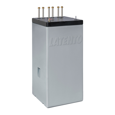
DEHOUST AQF 570/5 User manual

Break tank system AQF
For protection of drinking water from process water in hazard class 5 in
accordance with DIN EN 1717
Operating and installation guide
Current as of October 2015

Table of contents
1. Safety information....................................................................................................... 1
1.1. Safetyinformation inthis manual............................................................................................ 1
1.2. General safety information...................................................................................................... 1
1.3. Other safety regulations.......................................................................................................... 1
1.4. Consequencesandrisksof non-compliancewith the manual ................................................. 2
1.5. Operator'sdutyof care............................................................................................................ 2
1.6. Safetyinstructionsfor service, inspection andinstallation work............................................. 2
1.7. Requirements for operating personnel .................................................................................... 3
2. General information .................................................................................................. 3
2.1. Warranty and liability ………………………………………………………………………………….……………………. 3
2.2. Legal warranty obligation(excerpt)........................................................................................ 3
3. Description.................................................................................................................. 4
3.1. Functionaldescription.............................................................................................................. 4
3.2. Technical specifications ............................................................................................................ 4
3.3. Scope ofdelivery ....................................................................................................................... 5
3.4. Structure..................................................................................................................................... 6
3.5. Intended use.............................................................................................................................. 6
3.6. Unauthorised use........................................................................................................................ 7
4. Transport ..................................................................................................................... 7
5. Installation ................................................................................................................... 7
5.1. Assemblyarea ............................................................................................................................ 7
5.2. Immersion pressure pumpin thestorage tank.......................................................................... 7
5.3. Connection towater pipes ......................................................................................................... 8
5.4. Emergencyoverflow connection ............................................................................................... 9
5.5. Emergencyoverflow venttype AB............................................................................................ 10
5.6. Electrical connection................................................................................................................ 11
6. Commissioning ........................................................................................................... 11
6.1. Fill container and start immersion pressurepump ...................................................................11
7. Maintenance .............................................................................................................. 12
7.1 Inspections ................................................................................................................................ 12
7.2. Service.......................................................................................................................................13
8. Malfunctions/troubleshooting..................................................................................... 14
9. Disposal. ..................................................................................................................... 14

1
DEHOUST GMBH – GUTENBERGSTR. 5-7 – D-69181 LEIMEN – www.dehoust.com
1. Safety information
1.1. Safety information in this manual
Areas labelled with this sign refer to technical information and application tips that should help to avoid damage to
the system. This symbol does not indicate a safety instruction.
Areas labelled with this sign indicate that slight physical injury or minor property damage may occur if appropriate
safety measures are not followed.
Areas labelled with this sign indicate that death or serious physical injury or substantial property damage may
occur if appropriate safety measures are not followed.
1.2. General safety information
This manual contains basic information that should be followed during transport, installation, commissioning, operation,
maintenance, shutdown, storage and disposal. For the use of the break tank system the authorised data, operating and usage
conditions specified in the data sheet must be followed.
Never exceed the permissible usage limits concerning pressures, temperature, etc. that are listed in the documentation.
Follow all safety information and handling instructions in the present manual.
Information attached directly to the system must be followed and must be kept in legible condition. This applies for example
for:
Safety information
Labels for connections
Type plate
Before installation and commissioning, the manual must be read by the operator and by the assigned technician/operator
and must be available at all times at the usage location of the break tank system.
Installation and maintenance work is be performed only by authorised specialists with appropriate equipment.
The technical condition of the break tank system must be checked at regular
time intervals (at least once per year).
The local safety and accident prevention rules must be followed for the operation of the break tank system.
General rules of technology must be followed for resource planning and the operation of the unit.
Modification of the break tank system is prohibited and will invalidate warranty claims.
The operator is responsible for compliance with the local rules in effect on site but not included in the manual.
1.3. Other safety regulations
In addition to the safety instructions listed in this manual as well as those "Intended use", the following safety provisions all
apply:
• Accident prevention rules, safety and operating rules
• Safety rules for handling hazardous materials
• Relevant standards and laws

2
DEHOUST GMBH – GUTENBERGSTR. 5-7 – D-69181 LEIMEN – www.dehoust.com
1.4. Consequences and risks of non-compliance with the manual
• Failure to follow this manual will invalidate warranty and damage compensation claims.
• Failure to follow it may, for example, result in the following risks::
Risk to persons from electrical, thermal, mechanical and chemical influences
Failure of important functions of the product
Failure of specified methods for maintenance and service
1.5. Operator's duty of care
The break tank system was designed and built based on a risk assessment and after acareful selection of the required harmonised
standards, as well as other technical specifications. It is thus consistent with state-of-the-art technology and ensures maximum
safety. But this safety can only be achieved during actual operation if all the required measures are taken. It falls within the duty
of care of the break tank system operator to plan these measures and monitor their implementation. The operator must ensure, in
particular, that
the break tank system is operated only for its intended use
the break tank system is only operated in correct technical condition.
The manual is always legible and available in its entirety at the operation site of the break tank system.
only properly qualified and authorised personnel install, operate, service and decommission the break tank system.
this personnel is regularly trained in all relevant matters concerning occupational safety and environmental protection, and
has understood the manual and in particular has read and understood the safety instructions contained in it.
safety and warning signs on the break tank system are not removed and all remain legible
any other hazards that arise from the specific working conditions at the operation site of the break tank system are
investigated in a risk assessment (as defined in the Occupational Safety and Health Act § 5).
all additional instructions and safety advice arising from the risk assessment are compiled in a user guide (as defined under
the German Work Equipment Usage Ordinance § 6).
the duct routing is assessed properly.
1.6. Safety instructions for service, inspection and installation work
Any alterations and modifications of the machine without the consent of the manufacturer are prohibited.
Only use original parts or those authorised by the manufacturer. The use of other parts can result in the
invalidation of void your warranty for any consequences resulting there from.
Only work on the machine when it is turned off.
The pump housing must be at ambient temperature.
The pump housing must be de-pressurised and emptied.
Strictly follow the procedures for decommissioning the system, as described in these instructions.
After completion of work, immediately reattach or restart any safety and protection equipment.
Before restarting equipment, make sure that the listed points for commissioning are followed.
Keep any unauthorised persons (e.g. children) away from the system.

3
DEHOUST GMBH – GUTENBERGSTR. 5-7 – D-69181 LEIMEN – www.dehoust.com
1.7. Requirements for operating personnel
This break tank system must be assembled, commissioned, repaired and decommissioned only by persons who have been trained,
instructed and authorised for this purposed. If necessary, training can be provided by the manufacturer/supplier at the request of
the operator. Training sessions on the system are to be conducted with the supervision of technical professionals. The relevant
authorisations of personnel must be clearly specified by the operator in the form of a user guide. Special qualifications are
additionally required for the following activities:
Work on the electrical equipment is to be carried out only by trained electricians only.
Assembly, maintenance and repair work must be carried out only by qualified professionals.
The basic regulations for occupational safety and accident prevention must be followed.
2. General information
The manual is part of the specified series and its models. The manual describes the proper and safe use of the equipment in all
operating phases. The type plate indicates the series and size, the most important operational data and the serial number. To
uphold any warranty claims in the event of damage, the authorised dealer must be immediately notified with the installation site
and serial number of the machine.
2.1. Warranty and liability
The general delivery conditions and terms of sale of DEHOUST shall apply. Any warranty and liability claims for personal or
material damage are void if they can be attributed to one or more of the following causes.
Improper use of the break tank system
Improper assembly, commissioning, operation and maintenance of the break tank system
Non-compliance with the instructions in the manual regarding transportation, storage, assembly, commissioning, operation,
maintenance and repair of the break tank system
Unauthorised structural modifications to the break tank system
Improperly performed repairs
Disasters caused by third party exposure and force majeure
2.2. Legal warranty obligation (excerpt)
Statutory warranty applies in accordance with § 437 BGB
(German Civil Code).
Within the warranty period, DEHOUST shall rectify free-of-charge any functional disturbances which can be attributed to production
or material defects. This includes all faults that occur despite verifiably proper installation, proper operation and compliance with
all operational and installation guides.

4
DEHOUST GMBH – GUTENBERGSTR. 5-7 – D-69181 LEIMEN – www.dehoust.com
3. Description
The break tank system performs the separation of drinking water from fluids of category 5 under DIN EN 1717 and prevents
recontamination in the central mains water network. The DIN EN 1717 requires the separation of fluids in category 5 from drinking
water. Examples of category 5 fluids are rainwater, process water from grey water utilisation, well water, as well as applications in
the areas of agriculture, slaughter houses, laboratory equipment, of irrigation systems, agricultural operations, slaughterhouses
and subsurface irrigation systems.
3.1. Functional description
A mechanical float valve (closes by float lift) regulates the fill level and the feed that is required in the tank. As water is drawn, the
water level drops and the mechanical float valve opens, allowing drinking water to flow into the tank. When water is no longer being
drawn, the level in the tank rises again and the mechanical float valve switches off the drinking water feed once the maximum level
is reached. The immersion pressure pump installed in the tank has an integrated automatic switch and dry-run protection. In case
of a pressure drop to approx. 2.5 bar in the process water line, this is registered by the automatic switch and the immersion
pressure pump is switched on until the switch-off pressure is reached again. The immersion pressure pump will continue running
for approx. 10 seconds after reaching the switch-off pressure.
To reduce the switching frequency of the pressure booster, the installation of a membrane pressure
expansion vessel of at least 50 litres in volume is recommended in the process water pressure line. The
membrane pressure expansion vessel must be suitable for operation with process water. The primary
pressure in the membrane pressure expansion vessel must be 0.3 to 0.5 bar below the start-up pressure of
the pump.
3.2. Technical specifications
Table 1: Technical details on break tank system
Name Break tank system
AQF 570/5
Article number
812903
Medium Process water
Nominal contents of storage tank
495 litres
Delivery rate
max. 5.5 m³/h
Delivery height
max. 48 m
Operating
pressure
max. 10 bar
Flow pressure drinking water field
min. 1 bar; max. 5 bar
max. flow quantity drinking water at
4 bar flow pressure 6 m³/h
Medium temperature drinking water
+ 5°C to 20 °C
Connection drinking water line
3/4“ inside thread
Connection process water line
1“ outside thread
Connection overflow line
DN 70
Mains voltage
230 V AC , 50 Hz, 16 A
Power consumption: 1,125 Watt input
Ambient temperature
5°C to 20 °C
Empty weight
32 kg
Total weight with filled storage
container 525 kg
Dimensions of complete system
LxWxH [mm] 720 x 720 x 1,730

5
DEHOUST GMBH – GUTENBERGSTR. 5-7 – D-69181 LEIMEN – www.dehoust.com
Figure 1: pump characteristic curve of the break tank system 505
3.3. Scope of delivery
Ready-to-connect break tank system, consisting of:
Storage tank 570 litre type Aquaform
Emergency overflow connection DN 70 on storage tank
Type AB drinking water feed according to DIN EN 1717
Mechanical float valve for regulation of fill level quantity
Immersion pressure pump
HDPE pressure pipe with quick-close
Connection line of break tank system incl. 2 m connecting cable
User guide

6
DEHOUST GMBH – GUTENBERGSTR. 5-7 – D-69181 LEIMEN – www.dehoust.com
3.4. Structu
re
Figure 2: Structure of the break tank system: front side
3.5. Intended use
The break tank system may only be used in usage areas that are described in this manual. Unintended use of the break tank
system can result in danger to persons, systems in the surrounding area and the environment.
Do not operate the break tank system unless it is in proper condition technically.
Do not operate the break tank system in partially assembled condition.
The break tank system can only pump the medium described in the documentation of the relevant version.
Never operate the break tank system without pumping medium.
The minimum volumetric flow cannot exceed 2 l/min (0.12 m³). A lower volumetric flow of the consumers will result in
unusually frequent switching on and off of the immersion pump. In this case an appropriately dimensioned expansion vessel
must additionally be placed in the pressure line.
Do not restrict the break tank system on the input side (avoiding cavitation damage).
Agree on alternative operating modes with the manufacturer, if not stated in the documentation.
Storage tank 570 L
Aquaform AQF
Immersion pressure pump with
integrated automatic switch
Overflow DN 70
Rectangular overflow
according to EN 1717
Drinking water connection
¾“
Process water connection 1“

7
DEHOUST GMBH – GUTENBERGSTR. 5-7 – D-69181 LEIMEN – www.dehoust.com
3.6. Unauthorised use
The break tank system is not intended for use outdoors. Temperature, light and humidity influences can result in malfunctions
and damage to the device.
Do not use the break tank system outdoors.
Only use the break tank system for its intended purpose.
Do not fill the media connections of the system with aggressive or flammable media.
Do not apply mechanical loads to the housing (e.g. by using it to store objects or a step).
Do not make external changes to the device housings. Do not paint housing parts and screws!
Do not disassemble the break tank system beyond the degree needed for installation and service.
4. Transport
The product must not be connected to the electrical feed line during transport. During transport, it is important to protect the device
from being knocked and dropped. The product must be stored in a dry, cool and sun-protected, as well as frost-proof room.
Each packaging unit must be checked for damage at goods transfer. In case of transport damage, determine and document the
exact damage and immediately report to DEHOUST in writing.
5.
Assembly
5.1. Assembly
area
The break tank system must be set up in a frost-proof, dry and well ventilated room on ground level and on a level surface. The
load-bearing capacity must be equal at a minimum to the total weight of the break tank system in filled operating condition (see
3.2). The room temperature must not exceed the maximum permissible temperature (see
3.2) to minimise hygienic risks in the process water storage tank.
Do not operate the break tank system near living rooms or bedrooms due to the noises caused by feed units and
pumps.
Observe the space requirements for operation and repairs.
A suitable sound insulation panel can be used to create the sound decoupler between the storage tank of
the break tank system and the building.
The installation room must have a suitable floor drain/sump to securely drain away the overflowing water in case
of backflooding over the emergency overflow vent of the process water storage tank.
5.2. Immersion pressure pump in the storage tank
The immersion pressure pump comes already installed in the storage tank and bolted to the pressure connection of the immersion
pressure pump and at the top middle tank lid with HDPE pressure pipe and a quick connector. The power cable is threaded through
the tank lid with steel conduit threading.

8
DEHOUST GMBH – GUTENBERGSTR. 5-7 – D-69181 LEIMEN – www.dehoust.com
The immersion pressure pump must be positioned vertically in the storage tank. Please check whether the pump
has slipped into another position during transport.
The immersion pressure pump must not be in hanging, lowered or suspended position during transport.
Figure 3: connection of HDPE pressure pipe with immersion pressure
pump
5.3. Connection to water pipes
5.3.1. Drinking water feed
Connect the drinking water line with the mechanical float valve (3/4“) of the break tank system and seal.
Connect the connection line in de-energised state. There should not be any forces applied to the connection
sockets and system. Install a pressure reducer in front of the system if necessary to ensure that no more than 5
bar of primary pressure is fed from the drinking water network. We recommend installing a shut-off valve, a
detachable screw and an external fine water filter.
The feed volumes of the mains water feed must be within the range of the stated flow pressure (see 3.2) to
ensure the long-term reliability of supply of the immersion pressure pump with sufficient water guarantees.
HDPE pressure
pipe
Immersion
pressure pump
Screw the HDPE pressure pipe and the
immersion pressure pump together tightly

9
DEHOUST GMBH – GUTENBERGSTR. 5-7 – D-69181 LEIMEN – www.dehoust.com
Figure 4: Connection of the drinking water feed
5.3.2. Process water line
Connect and seal the process water pressure line with the brass threaded connection (see 3.2) on the middle tank cover of the
break tank system.
Connect the pressure line in de-energised state. There should not be any forces applied to the brass threaded
connection of the system. We recommend installing a shut-off valve and a detachable screw.
Figure 5: Connection of the process water line
5.4. Emergency overflow connection
Connect the emergency overflow connection DN 70 (see 3.2) of the break tank system with the channel interface or a suitable
pump system. For this purpose, insert a DN 70 HT pipe of approx. 2-3 cm into the provided DN 70 green lip seal and install the
pipe according to the intended connection.
This overflow becomes active if the mechanical float valve of the drinking water feed line has a malfunction and the water rises
over the maximum fill level in the storage tank.
Connection of the mechanical
float valve to the drinking
water line

10
DEHOUST GMBH – GUTENBERGSTR. 5-7 – D-69181 LEIMEN – www.dehoust.com
To avoid unpleasant odours from the sewage drain, a siphon is fitted as standard to the process water storage tank
The drain connection or pump system must be able to securely drain the maximum mains water feed volume
(see 3.2).
Make sure the overflow line to the sewer/pumping system has the same nominal width as the emergency overflow
connection (no cross-section constriction!)
If the overflow connection is not connected to the drain, there is a risk that the installation room
may overflow.
Figure 6: Connection of the overflow connection
5.5. Emergency overflow vent
type AB
If a backflow occurs, due to a drain blockage/defect of the pumping station, extending into the process water storage tank of the
break tank system, the water is drained through the tank’s side emergency overflow vent into the installation room. This free
overflow is required to protect the mains water back-up line in accordance with DIN EN 1717.
The installation room must have a suitable floor drain/sump to securely drain away the overflowing water in case
of backflooding over the drinking water feed of the process water storage tank.
Figure 7: type AB side emergency overflow vent
Connection of the overflow
connection
DN 70 to sewer/pumping system
Type AB side emergency overflow
vent

11
DEHOUST GMBH – GUTENBERGSTR. 5-7 – D-69181 LEIMEN – www.dehoust.com
5.6. Electrical connection
Check the mains voltage data on the type plate with the relevant mains voltage.
Do not plug in the mains plug of the immersion pump of the break tank system until the break tank system needs to be started
(see 6). The system switches on automatically as soon as the mains plug is plugged into the socket.
The electrical system must conform to the general requirements for installation IEC 364 / VDE 0100, i.e. sockets
with earthing terminals. The electrical network to which the equipment is connected must have a residual current
operated circuit breaker (RCCB) in accordance with DIN EN 60335-2-41 / VDE 0700.
6. Commissioning
Commissioning of the system must be performed by qualified personnel only (see 1.5).
Before commissioning the break tank system, the following points must be ensured:
The break tank system is electrically connected to all protection equipment in accordance with requirements.
The relevant VDE and country-specific rules have been followed and are being complied with.
Mechanical float valve for the drinking water feed is connected to the drinking water network.
Process water connection is connected to the process water line.
System is correctly connected electrically.
6.1. Fill container and start immersion pressure pump
1. Open the shut-off valve on the drinking water connection and the tank will automatically fill with drinking water.
2. As soon as the vessel if filled, the mechanical float valve switches the drinking water feed off. Next, open the
connected process water consumer and insert the mains plug of the break tank system into the socket.
a.. The immersion pressure pump starts automatically.
b. Open the process water consumer until the water is pumped, free of bubbles, then close the consumer.
c. The immersion pressure pump shuts off automatically after a short follow-up time.
d. Drinking water feed shuts off when a defined maximum fill reach is reached.
3. The break tank system is ready for operation.
When the process water consumer opens, the immersion pressure pump automatically switches on beginning at a line pressure
of approx. 2.2 bar and continues pumping process water until all process water consumers have closed. In case of insufficient
water, the integrated dry-run protection switches the immersion pressure pump off.
7. Maintenance
The break tank system includes components that require inspection and maintenance .

12
DEHOUST GMBH – GUTENBERGSTR. 5-7 – D-69181 LEIMEN – www.dehoust.com
Inspections must be performed only by the operator of the system themselves.
Maintenance and repairs must be performed by qualified specialists only (see 1.8).
The time intervals listed for inspection and maintenance work as well as the specified work steps should be followed
by the operator in their own interest!
7.1. Inspections
If defects/damage are observed on the break tank system during the inspection, please contact your contract partner/dealer.
7.1.1. Aquaform AQF storage tank
Inspect the storage tank for leakproofness, cleanliness, damage and sediment residues. Clean
external dirt with a wet towel and standard dishwasher detergent.
Time interval: yearly
When cleaning, take care to ensure that liquids cannot get on electrical parts.
7.1.2. Checking water connections
Check the drinking water and process water connection for damage, leakproofness and for porous or worn
spots. If necessary, replace hoses/pipes and seal. Time interval: half-
yearly
7.1.3. Mechanical float valve
Check the mechanical float valves for functioning. Open the process water consumer and wait until the fill level in the break tank
system has fallen so that the ball valve is open. Close the process water consumer again and wait until the ball valve closes again.
Time interval: half-
yearly
7.1.4. Functioning of immersion pressure pump
Check pressure accumulation, leakproofness, pumping and flowing noises as well as functioning. Open process water
consumers and thus start immersion pressure pump.
Time interval: half-yearly
7.1.5. Dry-run protection of the immersion pressure pump
Shut off drinking water feed and open process water consumers until storage tank is pumped empty. The integrated dry-run
protection switches the immersion pressure pump off automatically. Next, open the drinking water feed again andclose the process
water consumers. The dry-run protection will automatically reset after 3 min.
Time interval: half-
yearly
7.2. Service
The break tank system must be disconnected from the mains network (main switch OFF position) during
maintenance and repair work. The break tank system is not available during the tasks.

13
DEHOUST GMBH – GUTENBERGSTR. 5-7 – D-69181 LEIMEN – www.dehoust.com
7.2.1. Slide ring seal/bearing of immersion pressure pump
An exchange of the slide ring seal is recommended after 10,000 hours of operation or after 10 years whichever is sooner. In case
of early wear and tear, the slide ring seal should also be replaced.
7.2.2. Removal of the immersion pressure pump
The immersion pressure pump is connected in the inside of the tank through an electrical plug connection. When it is necessary
to remove the immersion pressure pump, the electrical plug connection can be disconnected and the immersion pressure pump
can be removed. The pressure hose must be removed by disconnecting the hose clip from the hose socket.
Electrical plug connector - PIN assignment of immersion pressure pump: 1; 3; PE

14
DEHOUST GMBH – GUTENBERGSTR. 5-7 – D-69181 LEIMEN – www.dehoust.com
8. Malfunctions/troubleshooting
Error Possible causes Action Implementation by
__________________________________________________________________________________________________
Backflow to side Dirt accumulation/impurity in the float- shut-off valve in the drinking water- Operator
emergency overflow vent Valve and emergency overflow Close line
connection clogged
Flush out the overflow line
Clean float valve, Service
if necessary, replace
__________________________________________________________________________________________________
Storage tank overflows over Dirt accumulation/impurity in the float- shut-off valve in the drinking water- Operator
emergency overflow connection Valve Clean float valve, Service
if necessary, replace
___________________________________________________________________________________________________
Storage tank empty Shut-off valve in drinking water- Shut-off valve in drinking water- Operator
Line closed Open line
Float switch switches Check float switch Service
Not correct reposition, if necessary, replace
Dry-run immersion pressure Drinking water feed volume Pressure reducer or shut-off valve
pump Not sufficient check and adjust Service
Dry-run protection is automatically reset after 3 min.. After 4 unsuccessful starts, reset time
interval is increased to 1 hour. After 4 more unsuccessful starts, time
is increased to 24 hours.
___________________________________________________________________________________________________
Immersion pressure pump cycles Process water line and/or Process water line and/or Operator
Consumer not leakproof Consumer not leakproof
Immersion pressure pump dirty Clean immersion pressure pump Service
Primary pressure in membrane Primary pressure in membrane-
pressure expansion vessel - Modify expansion vessel Service
Tank too small
___________________________________________________________________________________________________
Immersion pressure pump RCD is triggered Check insulation resistance Service
switches off
9. Disposal
The packaging material is to be recycled.
The product should be sent carriage free to the manufacturer, DEHOUST GmbH –
department GEP.
Table of contents
Popular Tank Equipment manuals by other brands
STM
STM DD210 manual

Mueller
Mueller 9865302 owner's manual

morse
morse 4560SS-P Operator's manual

Regulus
Regulus RBC 200 HP Installation and operation manual
Regulus
Regulus PS2F 3000 N25 Installation and operation manual
Franklin Fueling Systems
Franklin Fueling Systems NANOVAPOR NV-SS ST-1000 Installation and operation guide