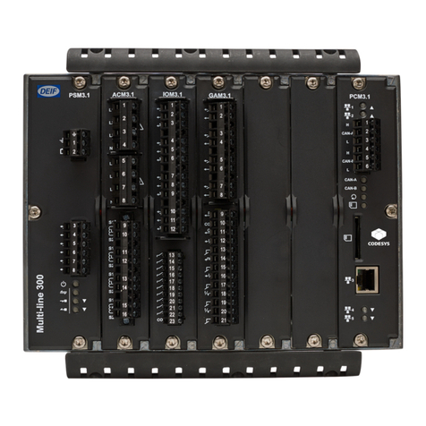
Deif Multi-line 2 Instruction Manual

DEIF
A/S
Multi-line 2 – version 2
4189340317C
General Guidelines for
Commissioning
•
Settings check
•Governor check
•AVR check
•Protections check
•Adjustment
•Troubleshooting
DEIF A/S, Frisenborgvej 33 Tel.: +45 9614 9614, Fax: +45 9614 9615

Multi-line 2 General Guidelines for Commissioning
DEIF A/S Page 2 of 19
Table of contents
1. ABOUT THIS DOCUMENT....................................................................................................3
GENERAL PURPOSE......................................................................................................................3
INTENDED USERS .........................................................................................................................3
CONTENTS/OVERALL STRUCTURE..................................................................................................3
2. WARNINGS AND LEGAL INFORMATION ...........................................................................4
LEGAL INFORMATION AND RESPONSIBILITY ....................................................................................4
ELECTROSTATIC DISCHARGE AWARENESS.....................................................................................4
SAFETY ISSUES............................................................................................................................4
DEFINITIONS ................................................................................................................................4
3. COMMISSIONING OF THE MULTI-LINE 2 ..........................................................................5
STEP BY STEP..............................................................................................................................5
4. SETTINGS CHECK................................................................................................................6
SETTINGS ....................................................................................................................................6
NOMINAL VALUES .........................................................................................................................6
ALARM SETTINGS .........................................................................................................................7
FUNCTION CONTROL SETTINGS .....................................................................................................7
SPEED CONTROLLER SETTINGS.....................................................................................................8
VOLTAGE CONTROLLER SETTINGS.................................................................................................9
5. GOVERNOR CHECK...........................................................................................................10
SPEED SETTING .........................................................................................................................10
SPEED DROOP ...........................................................................................................................11
SPEED RANGE............................................................................................................................11
TERMINALS................................................................................................................................11
6. AVR CHECK ........................................................................................................................13
VOLTAGE SETTING......................................................................................................................13
VOLTAGE DROOP........................................................................................................................14
VOLTAGE RANGE........................................................................................................................14
TERMINALS................................................................................................................................14
7. PROTECTIONS CHECK......................................................................................................15
CONSIDERATIONS.......................................................................................................................15
CONFIGURATION OF THE PROTECTIONS.......................................................................................15
8. ADJUSTMENT.....................................................................................................................16
ADJUSTING PI CONTROLLER .......................................................................................................16
ADJUSTMENT HINTS FOR AGC....................................................................................................17
RELAY OUTPUT ADJUSTMENTS....................................................................................................17
RESULTING SPEED/VOLTAGE CURVE UPON LOAD CHANGE ............................................................18
9. TROUBLESHOOTING.........................................................................................................19

Multi-line 2 General Guidelines for Commissioning
DEIF A/S Page 3 of 19
1. About this document
General purpose
This document includes general guidelines for commissioning of DEIF’s multi-line 2 units. It
mainly includes instructions for settings, governor, AVR and protections check and unit
adjustment. The general purpose of the document is to supply general guidelines to be used in
the commissioning of the multi-line 2.
Intended users
These guidelines are mainly intended for the person responsible for the commissioning of the unit.
In most cases, this would be a commissioning engineer.
Contents/overall structure
The General Guidelines for Commissioning is divided into chapters, and in order to make the
structure of the document simple and easy to use, each chapter will begin from the top of a new
page.
Please make sure to read this handbook before working with the multi-line 2
controller and the gen-set to be controlled. Failure to do this could result in
damage to the equipment or human injury.

Multi-line 2 General Guidelines for Commissioning
DEIF A/S Page 4 of 19
2. Warnings and legal information
Legal information and responsibility
DEIF takes no responsibility for installation or operation of the generator set. If there is any doubt
about how to install or operate the generator set controlled by the unit, the company responsible for
the installation or the operation of the set must be contacted.
Electrostatic discharge awareness
Sufficient care must be taken to protect the terminals against static discharges during the
installation. Once the unit is installed and connected, these precautions are no longer necessary.
Safety issues
Installing the unit implies work with dangerous currents and voltages. Therefore, the installation
should only be carried out by authorised personnel who understand the risks involved in working
with live electrical equipment.
Definitions
Throughout this document a number of notes and warnings will be presented. To ensure that these
are noticed, they will be highlighted in order to separate them from the general text.
Notes
Warning
The notes provide general information which will be helpful for the reader to
bear in mind.
The warnings indicate a potentially dangerous situation which could result in
death, personal injury or damaged equipment, if certain guidelines are not
followed.
Be aware of the hazardous live currents and voltages. Do not touch any AC
measurement inputs as this could lead to injury or death.
The units are not to be opened by unauthorised personnel. If opened anyway, the
warranty will be lost.

Multi-line 2 General Guidelines for Commissioning
DEIF A/S Page 5 of 19
3. Commissioning of the multi-line 2
Step by step
The illustration below indicates the overall steps to be followed in order to carry out a successful
commissioning of the multi-line 2 unit.
Step 1 Settings check
Step 2 Governor check
Step 3 AVR check
Step 4 Protections check
Step 5 Adjustment
In addition, the generic troubleshooting in chapter 9 can be used.

Multi-line 2 General Guidelines for Commissioning
DEIF A/S Page 6 of 19
4. Settings check
Settings
It is necessary to perform a settings check. This is done following five individual steps:
1. Check and adjust the nominal settings.
2. Check and adjust the alarm settings.
3. Check and adjust the function control settings.
4. Check and adjust the speed controller settings.
5. Check and adjust the voltage controller settings.
The above-mentioned settings must be checked and adjusted prior to the initial starting of the
gen-set.
Nominal values
The nominal values of the multi-line 2 are adjusted in the system setup menu.
In the PC utility software it is presented as illustrated on the screen dump above. The correct
values are supplied by the switchboard manufacturer.
The settings can be adjusted either through the display or through the PC utility
software. For navigating in the menus see the Operator’s Manual.

Multi-line 2 General Guidelines for Commissioning
DEIF A/S Page 7 of 19
Alarm settings
The alarm settings are adjusted in the protection setup menu.
In the PC utility software it is presented as illustrated on the screen dump above or similar. The
screen dump includes the protection alarms of the standard multi-line 2. The number of alarms
depends on the options selection of the individual unit. The actual alarm parameters are adjusted
according to customer requirements and application requirements.
Function control settings
The function control settings are adjusted in the system setup and the power setup menu.
In the screen dump above, the adjustments for the start and stop sequences are illustrated. Since
the function control settings include parameters for the entire functionality of the multi-line 2, they

Multi-line 2 General Guidelines for Commissioning
DEIF A/S Page 8 of 19
must be stepped through carefully. The function control settings are adjusted according to the
desired unit control.
Speed controller settings
The multi-line 2 speed controller settings are adjusted in the control setup menu.
The screen dump below illustrates the controller settings related to the speed governor. As an initial
setting before the first start up, the KPand KIof the frequency and power controllers are set to a low
value.
In need of detailed information about the requirements, contact the switchboard
manufacturer.

Multi-line 2 General Guidelines for Commissioning
DEIF A/S Page 9 of 19
Voltage controller settings
The voltage controller settings are adjusted in the control setup menu.
The screen dump above illustrates the controller settings of the voltage and var controller. As an
initial setting before the first start up, the KPand KIof the voltage and var controllers are set to a low
value.

Multi-line 2 General Guidelines for Commissioning
DEIF A/S Page 10 of 19
5. Governor check
Even if the engine manufacturer has adjusted the governor, it is necessary to carry out the
following adjustments to be sure that the multi-line 2 can successfully operate with the speed
governor.
The governor should be tuned in according to the governor/engine manufacturer’s instructions. It
is important that the engine is able to run smoothly and without hunting before the control
function of the multi-line 2 is activated.
Speed setting
An initial speed setting must be made.
Relay output
•Disable the outputs from the multi-line 2.
•Run the generator with no load (open generator breaker).
•Adjust the frequency (on the speed governor) to be base frequency (50 or 60Hz).
Analogue output
The analogue output is a +/- 20mA signal which in most cases must be converted into a voltage
using a resistor across the terminals (150Ωgives 3V DC at 20mA, etc).
Given the fact that especially the governors are sensitive to the external circuit impedance, it is
essential to carry out the initial setting of speed governor while the multi-line 2 is connected and
the control function disabled.
Putting the multi-line 2 in manual operation disables the control function. This will ‘disable’ the
control outputs, but the generator protection is still active. If you fail to do this, you may
experience control problems later on.
AGC/BGC:
•Go to MAN mode.
•Reboot the unit or activate the input ‘reset analogue controller outputs’.
•Run the generator with no load (open generator breaker).
•Set the frequency (on the speed governor) to be base frequency (50 or 60Hz).
GPU/GPC/PPU:
•Deactivate terminal 25.
•Reboot the unit or activate the input ‘reset analogue controller outputs’.
•Run the generator with no load (open generator breaker).
•Set the frequency (on the speed governor) to be base frequency (50 or 60Hz).
With multi-line 2 PPU/GPC/AGC PWM output for Caterpillar®
Since the PWM initial setting has an influence on the start-up speed of the engine, the first thing
to do is to set this (setting 2272 for multi-line, 2662 for AGC):
The speed setting procedure depends on the interfacing.

Multi-line 2 General Guidelines for Commissioning
DEIF A/S Page 11 of 19
-Make sure that the generator cannot start.
-Turn the PPU/GPC/AGC OFF and ON again (to make sure that the PWM output is reset).
-Start the generator (no load).
-Adjust setting 2272/2662 until the correct speed (and frequency) is achieved.
Speed droop
The speed governor must have a speed droop of 3-4% (speed dropping 3-4% from no load to
full load, when the multi-line 2 is not in control). In order to ensure equal load sharing on parallel
running machines, all governors must have the same droop setting.
Speed range
When using the analogue interfacing, the resistor installed across the output terminals is
selected to obtain the necessary speed range. When finding the correct resistor, several aspects
must be considered.
The necessary speed range must be selected to make operation at full load possible. Typically,
this is fNOM + 3Hz. If the speed range is too high, then the resistor size must be decreased. If the
speed range is too low, then the resistor size must be increased.
Terminals
The governor can either be prepared for analogue interfacing or digital interfacing. When
analogue interfacing is used, a +/- 20mA signal from the multi-line 2 is applied. This signal can
be converted to the necessary voltage level. When digital interfacing is used, two relays are
used as increase/decrease outputs.
The terminals must be identified depending on the necessary interfacing. Some general
examples are shown in the illustrations below.
Digital interfacing
Motor potmeter
DEIF recommends adjusting the speed droop on the speed governor for stability
purposes. It is necessary in all cases when relay outputs for governor control is
used.
When analogue interfacing is used, it is possible to operate with a speed droop
adjustment of 0%, but for stability and safety purposes it is recommended to use
the speed droop adjustment.
The speed range must allow for the full load of the gen-set. If full load cannot be
reached, then the resistor size must be increased.

Multi-line 2 General Guidelines for Commissioning
DEIF A/S Page 12 of 19
Direct digital signals
Analogue interfacing
Direct analogue signal
External potmeter
For additional information about interfaces, see Interfacing DEIF Equipment to
Governors and AVRs available on www.deif.com.

Multi-line 2 General Guidelines for Commissioning
DEIF A/S Page 13 of 19
6. AVR check
Even if the AVR is adjusted by the gen-set manufacturer, it is necessary to go through the
following adjustments in order to be sure that the multi-line 2 can operate with the AVR.
The AVR should be tuned in according to the AVR/generator manufacturer’s instructions. It is
imperative that the gen-set is able to operate smoothly before the control function of the multi-
line 2 is activated.
Voltage setting
An initial voltage level setting must be made.
Relay output
•Disable the outputs from the multi-line 2.
•Run the generator with no load (open generator breaker).
•Adjust the voltage (on the AVR) to be nominal voltage.
Analogue output
The analogue output is a +/- 20mA signal which in most cases has to be converted into a
voltage using a resistor across the terminals (150Ωgives 3V DC at 20mA, etc).
Given the fact that especially the AVRs are sensitive to the external circuit impedance, it is
essential to carry out the initial setting of the AVR while the multi-line 2 is connected and the
control function disabled.
Putting the multi-line 2 in manual operation, MAN, disables the control function. This will ‘disable’
the control outputs, but the generator protection is still active. If you fail to do this, you may
experience control problems later on.
AGC/BGC
•Go to MAN mode.
•Reboot the unit or activate the input ‘reset analogue controller outputs’.
•Run the generator with no load (open generator breaker).
•Set the voltage (on the AVR) to be nominal voltage.
GPU/GPC/PPU:
•Deactivate terminal 25.
•Reboot the unit or activate the input ‘reset analogue controller outputs’.
•Run the generator with no load (open generator breaker).
•Set the voltage (on the AVR) to be nominal voltage.
The voltage level setting procedure depends on the interfacing.

Multi-line 2 General Guidelines for Commissioning
DEIF A/S Page 14 of 19
Voltage droop
The AVR controls the generator voltage in a way which is comparable to the speed governor
controlling the prime mover speed.
This means that the generator AVR must have a voltage droop of 3-4% (voltage dropping 3-4%
from no load to full reactive load when the multi-line 2 has no control). In order to ensure equal
var sharing on parallel running generators, all generators must have the same voltage droop
setting.
Voltage range
When using the analogue interfacing, the resistor installed across the output terminals is
selected to obtain the necessary speed range. The voltage range must be defined similar to the
speed range for the governor.
The voltage range must be wide enough for the voltage droop and for the full loading of the gen-
set. A typical value is +/- 10% * UNOM. The necessary control signal level is often specified
depending on the AVR type.
Terminals
The AVR can either be prepared for analogue interfacing or digital interfacing. When analogue
interfacing is used, a +/- 20mA signal from the multi-line 2 is applied. This signal can be
converted to the necessary voltage level. When the digital interfacing is used, two relays are
used as increase/decrease outputs.
The terminals must be identified depending on the necessary interfacing. Some general
examples are shown in the illustrations in the chapter about ‘governor check’.

Multi-line 2 General Guidelines for Commissioning
DEIF A/S Page 15 of 19
7. Protections check
As a part of the commissioning, the protections should be checked.
The following points must be considered for each alarm:
•Alarm set point.
•Alarm delay.
•Relay output.
•Activation.
•Fail class.
Considerations
Several issues must be taken into consideration when configuring the alarms. These are e.g.
national rules and requirements, additionally installed protection equipment, required use of the
protections (trip of non-essential load, breaker tripping and engine stopping). The switchboard
manufacturer and the end customer must take these considerations.
Configuration of the protections
The dialogue box shows a typical alarm.
For further information about the above-mentioned, see the Designer’s
Reference Handbook.
In the ‘commissioning’ field above, the horizontal line indicates the elapsed time
since the alarm set point was exceeded. In this example, the generator low
voltage set point is 95%. If the commissioning is done without the PC utility
software, then the timers can be seen in the service menu 4980/9120.

Multi-line 2 General Guidelines for Commissioning
DEIF A/S Page 16 of 19
8. Adjustment
The adjustment of the unit can be carried out when the initial settings of the governor and the AVR
are made.
The controller of the unit is a PI controller.
The unit includes different controllers which must be tuned in at the correct running situations (see
table below):
Controller Purpose Tune in conditions
Frequency controller Controls the frequency when the
multi-line 2 is in island mode
(stand-alone or load sharing).
Tune in when the generator
is running with the generator
breaker open.
Power controller Controls the power when the
multi-line 2 is running parallel to
the mains and when running in
load sharing mode.
Tune in when the generator
is running parallel to the
mains or in load sharing
mode.
Voltage controller Controls the voltage when the
multi line 2 is in island mode
(stand-alone or load sharing).
Tune in when the generator
is running with the generator
breaker open.
var controller Controls the vars when the
multi-line 2 is running parallel to
the mains and when running in
var sharing mode.
Tune in when the generator
is running parallel to the
mains or in load sharing
mode.
Adjusting PI controller
Before the PI controllers of the multi-line 2 are tuned in, the values of the KPand KIof all
controllers must be decreased to a low value.
Start by tuning in the KPfactor, and then tune in the KIfactor. Normally, the controllers are tuned
in following a few general rules as given below.
Step 1, adjustment of the KP
Only the P regulator is to be active, and the operation of the gen-set must be stable. Now
increase the KPfactor step by step, until the gen-set becomes unstable. Adjust the KPfactor to
50% of the value found above.
Step 2, adjustment of the KI
Step by step increase the KIvalue, until the gen-set becomes unstable. Adjust the KIfactor to
50…70% of the value found above.
Step 3, readjustment of controller settings
It can be necessary to make a readjustment of the controller settings, if during testing the gen-
set turns out to be unstable to some extent. If this is the case, then adjust the KPand/or KI, until
the operation is satisfactory.
To see the effect of the new adjustments when tuning in the multi-line 2,
remember to make a regulation deviation, e.g. by applying a load jump.

Multi-line 2 General Guidelines for Commissioning
DEIF A/S Page 17 of 19
Adjustment hints for AGC
In many cases it is difficult to tune in the controller using load jumps (no load bank available).
When this is the situation, the manual incr/decr inputs can be used in semi-auto mode. The
inputs are digital inputs that must be configured in the utility software.
When the manual increase/decrease input is activated, the regulator is switched off and an
offset will be given to the governor or AVR. The governor/AVR outputs will be activated as long
as the manual input is activated. When the input is deactivated again, the regulation will be
switched on, and the AGC will control gen-set towards the set point.
This is an easy way to make regulation deviations during the commissioning.
Relay output adjustments
If the relay outputs are used for the speed governor/AVR, then it will be necessary to adjust the
relay minimum pulse time and the period time.
There are 2 settings: ON time, which is the shortest relay ON signal time.
PER time, which is the period time.
The shortest acceptable pulse time is depending on the reaction of the governor/AVR and
connection type. Slow reaction requires a long time pulse.
As a starting point, use the following settings for the relay ON time and relay period time:
Menu text AGC GPC/PPU/GPU Setting Comment
Governor ON
time
Menu
2251 Menu 2641 500…1000ms
Governor
period time Menu
2252 Menu 2642 2500…5000ms It is recommended that the
period time is approximately
5*ON time.
AVR ON
Menu
2253 Menu 2643 100ms
AVR period
time Menu
2254 Menu 2644 500ms It is recommended that the
period time is approximately
5*ON time.
It is still necessary to tune in the PI controllers.
The number of digital inputs is option dependent.
This concerns the AGC only!

Multi-line 2 General Guidelines for Commissioning
DEIF A/S Page 18 of 19
Resulting speed/voltage curve upon load change
Testing is easily done by using (if possible) a load bank applying ‘jumps’ in the generator load,
thus testing the speed/voltage control.
The optimum result is indicated by this curve:
As indicated, 2-3 ‘overshoots’ before stabilising after a sudden change is OK. If more
‘overshoots’ are present, then decrease the KPfactor and try again.

Multi-line 2 General Guidelines for Commissioning
DEIF A/S Page 19 of 19
9. Troubleshooting
The troubleshooting table can be used for the uni-line and the multi-line 2 products.
Problem indication Problem cause Remedy
Load sharing or parallel with mains power
control unstable.
Synchronisation OK.
Single generator running frequency control
OK.
No speed droop on generators. Apply 3-4% speed drop on
prime mover governor.
Load sharing or parallel with mains voltage
(var) control unstable.
Synchronisation OK.
Single generator running voltage control OK.
No voltage droop on generators. Apply 3-4% voltage drop on
generator AVR.
Uni-line active power load sharing units only:
Load sharing or parallel with mains power
control unstable.
Synchronisation OK.
Single generator running frequency control
OK.
Speed droop OK.
Faulty connection of measuring
voltage and/or current transformer
input.
Correct connections.
Voltage on L1 and L2,
current transformer in L1.
Uni-line active power load sharing units only:
Load sharing stable but not equal.
Synchronisation OK.
Single generator running frequency control
OK.
Speed droop OK.
Load sharers have been mounted to
control the wrong size generators (can
happen in systems with different size
of generators).
Re-mount the load sharers
to match the generators.
The load sharers are pre-
configured for a specific
generator.
Uni-line reactive power load sharing units
only:
Load sharing or parallel with mains var
control unstable.
Synchronisation OK.
Single generator running voltage control OK.
Voltage droop OK.
Faulty connection of measuring
voltage and/or current transformer
input and/or voltage transducer.
Correct connections.
Voltage on L1 and L2,
current transformer in L1,
voltage transducer to US-
line (term. 38 (+) and 39
(-)).
Uni-line reactive power load sharing units
only:
var load sharing stable but not equal.
Synchronisation OK.
Single generator running voltage control OK.
Voltage droop OK.
var load sharers have been mounted
to control the wrong size generators
(can happen in systems with different
size of generators).
Re-mount the var load
sharers to match the
generators. The var load
sharers are preconfigured
for a specific generator.
Generator not able to take load to 100%. Initial setting of speed governor not
correct.
See chapters regarding
governor/AVR checks.
Generator not able to take load to 100%. Analogue output from DEIF equipment
has too low output range. Increase the full scale value.
This is mostly a case when
using electronic potentio-
meters.
Speed decreases when increase was
expected (relay outputs). Relay outputs ‘up’ and ‘down’
reversed. Swap connections.
Speed decreases when increase was
expected (analogue output). Outputs ‘+’ and ‘-‘ reversed. Swap connections.
Engine overspeeds when starting up. Regulator output is too high. Decrease the analogue
output signal by decreasing
the resistor.
DEIF A/S reserves the right to change any of the above
Other manuals for Multi-line 2
3
Table of contents
Other Deif Control Unit manuals