Del ozone Eclipse-1 User manual

DEL Ozone · SAN LUIS OBISPO, CA 93401 · USA · 800-676-1335 · Fax: 805-541-8459 111904 / 4-0308 Rev. F
Corona Discharge Ozone Generators
1, 2, & 4
INSTALLATION & OPERATION MANUAL

Table of Contents
DELZONE®Eclipse 1, 2, & 4 Corona Discharge Ozone Generators
SECTION 1
General Information
1A Description......................................................................... 1
1B Specications .................................................................... 1
1C WarrantySummary .......................................................... 1
SECTION 2
Installation
2A Location.............................................................................. 1
2B Mounting ............................................................................ 1
2C Electrical............................................................................. 1
2D Plumbing ............................................................................ 2
SECTION 3
Operation
3A General ............................................................................... 2
3B InitialSystemStart-Up ..................................................... 2
3C NormalOperation ............................................................. 2
3D SystemShut-Down............................................................ 3
3E WaterChemistry ............................................................... 3
SECTION 4
Maintenance & Service
4A SystemElectro-MechanicalOverview ............................ 3
4B SystemMaintenance........................................................ 3
4C GeneratorServicing .......................................................... 3
4D TroubleShooting ............................................................... 4
SECTION 5
Replacement Parts and Ordering
Information
5A OrderingInformation........................................................ 5
5B StandardReplacementPartsList .................................. 5
Warranty.....................................................................5
IMPORTANT SAFETY INSTRUCTIONS
Read and Follow All Instructions
• Read this manual completely before attempting installation.
•Allpermanentelectricalconnectionsshouldbemadebyaqualiedelectrician.
• For cord and plug-connected units, connect to a grounded, grounding type receptacle only. If the DELZONE®Eclipse electrical connection is to
be attached to the pool controls, be sure the pool controls are protected by a Ground Fault Circuit Interrupter (G.F.C.I.). If the DELZONE® Eclipse
is connected to an independent electrical supply, then a G.F.C.I. must be installed between the DELZONE®Eclipse and the electrical supply.
• Do not bury cord.
• Warning - To reduce the risk of electrical shock, replace damaged cord immediately.
• A pressure wire connector is provided on the outside of the unit to permit connection to a minimum No. 8 AWG (8.4 mm2) solid bond-
ing conductor between this point and any metal equipment, metal enclosures of electrical equipment, metal water pipes, or conduit
withinve(5)feet(1.5m)oftheunitasneededtocomplywithlocalrequirements.
• Install at least 5 feet (1.5 meters) from wall of pool water using nonmetallic tubing. Install ozone generator no less than one (1) foot
above maximum water level to prevent water from contacting electrical equipment. Install in accordance with the installation instruc-
tions.
• Follow all applicable electrical codes.
• Electric shock hazard. Be sure to turn power OFF and disconnect from power source before any service work is performed. Failure to
do so could result in serious injury or death.
• The DELZONE® Eclipse must be installed in an outdoor location, or indoors in a forced air ventilated room, and installed so that the
orientation is exactly as shown in Figure 1. Install to provide water drainage of generator to protect electrical components.
• Mount the DELZONE® Eclipse so that it is inaccessible to anyone in the pool. Never attempt any servicing while unit is wet.
• Plastic ozone supply tubing is supplied with the Eclipse. Never replace this tubing with metal tubing.
• Warning - Short-term inhalation of high concentrations of ozone and long term inhalation of low concentrations of ozone can cause
serious harmful physiological effects. DO NOT inhale ozone gas produced by this device.
•Foryoursafety,donotstoreorusegasoline,chemicalsorotherammableliquidsorvaporsnearthisoranyotherappliance.
SAVE THESE INSTRUCTIONS!
C

1B Specications
Ozone Output:
Ozoneoutput(+10%): Eclipse-1 (EC-1) .......0.25g/hr
Eclipse-2 (EC-2) ........0.5 g/hr
Eclipse-4 (EC-4) ........1.0 g/hr
Flowrate: 15scfh
Power Requirements:
Domestic:
EC-1 . . . . 120V, 60 Hz, 1Ø, 0.06 Amp
. . . . . . . . 240V, 60 Hz, 1Ø, 0.03 Amp
EC-2 . . . . 120V, 60 Hz, 1Ø, 0.12 Amp
. . . . . . . . 240V, 60 Hz, 1Ø, 0.06 Amp
EC-4 . . . . 120V, 60 Hz, 1Ø, 0.24 Amp
. . . . . . . . 240V, 60 Hz, 1Ø, 0.12 Amp
International:
EC-1 . . . . 240V, 50 Hz, 1Ø, 0.03 Amp
EC-2 . . . . 240V, 50 Hz, 1Ø, 0.06 Amp
EC-4 . . . . 240V, 50 Hz, 1Ø, 0.12 Amp
Shipping Weight:
EC-1: Approx. 3.5 pounds / 1.6 kg
EC-2: Approx. 5.5 pounds / 2.5 kg
EC-4: Approx. 10.5 pounds / 4.8 kg
Location Requirements:
Mounting:Wall mount in a clean, protected area.
AmbientTemp:30°F - 120°F (0°C - 50°C)
1
SECTION 1 General Information
1A Description
The DELZONE®Eclipse Corona Discharge (CD) series ozone
generators described in this manual are designed to provide
thebenetsofozonatedwaterinanenvironmentallysafeand
effective manner. The high quality, specially engineered compo-
nentsensureefcientozoneoutputandreliableperformance.
As a result of proper use of the DELZONE®Eclipse CD ozone gen-
erators, unpleasant effects of traditional chemical use are virtu-
ally eliminated. The DELZONE®Eclipse CD ozone generators are
safe and harmless to your equipment when installed properly.
SECTION 2 Installation
2A Location
The DELZONE®Eclipse units are designed for wall mount-
ing. See Figure 1. Mount generator in a clean, protected
area, either indoors or outdoors (Preferably out of direct
Sunlight). Locate generator out of reach of sprinklers or
drainage spouts. Allow sufficient access for maintenance
and all tubing and electrical wires. Ozone generator should
be installed at least (not less than) one foot above the maxi-
mum water level. Note: Injector manifold needs to be installed
after all other equipment or possible failure may occur.
2B Wall Mounting
1. Refer to Figure 1 to mark the locations for the four mount-
ing screws.
2. Install screws (or other hardware appropriate for mounting
surface) through the four mounting holes built in to the top
and bottom end caps on the Eclipse.
2C Electrical
2C-1. Main Power: Connect the DELZONE®Eclipse to the pool
timing clock so that the DELZONE® Eclipse operates simultane-
ously with the pool pump. The circuit must be protected by a
ground-fault circuit interrupter (GFCI) installed in accordance
to electrical code. Refer to the IMPORTANT SAFETY INSTRUC-
TIONS at the beginning of this manual for important wiring
information.
NOTE: The standard DELZONE® Eclipse is equipped with
apowercord that terminateswith a NEMA plug. Forunits
equippedwithaconduittting,connecttheBlackwiretoLine,
theWhitewiretoNeutral,andtheGreenwiretoGround.
2C-2. Grounding Lug: Using a 6-14AWG conductor, connect
the Grounding lug on the right side of the DELZONE®Eclipse
to an appropriate earth contact.
Figure 1 Wall Mount
DELZONE®Eclipse 1, 2, & 4 Corona Discharge Ozone Generators
1C Warranty Summary
Limited Warranty:
1 year warranty on entire generator. See Warranty section (page
5) for limitations and details on obtaining warranty service.

2D Plumbing
Ozone gas is introduced to the pool circulation line using a
venturi injector. Suction developed by the venturi allows the
DELZONE®Eclipse generator to operate safely under vacuum.
2D-1. Plumbing the Injector Manifold: The 2" DEL Adjustable
Injector Manifold (Figure 2) must be installed in the pool's
mainreturnlineafterallotherpoolequipment(pump,lter,
and heater).
Locate an appropriate section of the return line, hold the injec-
tor manifold against the pipe and mark the length. Subtract
2-1/2" from the overall length. Mark this point, and cut out the
section. Install the injector manifold with PVC cement. Be very
carefultoobserveandfollowthecorrectwaterowdirection
(as indicated by the arrow on the injector manifold).
2D-2. Water Check Valve: If the pool equipment is mounted
above the water line, a 1/3# DELCheckTM check valve must be
installed between the pump outlet and the injector assembly.
This will prevent the pump from draining and losing its prime
(When not in use).
2D-3. Ozone Gas Line - refer to Figures 3 & 4
1. The outlet on the injector assembly has a 1/4" hose port.
Connect the 1/4" ID ozone supply tubing provided to the
injector with a check valve between the two. Be sure that the
owdirectionarrowonthecheckvalveispointingtowards
the direction of the injector (away from the ozone generator).
2. Extend the ozone supply tubing so that it reaches the base
of the DELZONE®Eclipse in its mounted location.
3. Cut off the excess tubing so that the line from the injector
to the DELZONE®Eclipse is as straight and free from dips
and loops as possible.
4. The base of the DELZONE®Eclipse has two hose connec-
tions. Connect the 1/4" end of the ozone supply tubing to
the port marked "OZONE OUT" (see Bottom View - Figure 4).
NOTE: Plumbing the Ozone Line to the incorrect port will
cause damage to the ozone generator.
2D-4. Flowmeter: Connecttheowmeterassemblyprovided
tothe"AIRIN"portonthebaseoftheEclipse.Thisowmeter
will indicate how to adjust the injector after start-up. See
SECTION 3C.
Figure 3 Installation Diagram
Figure 2 DEL Adjustable Injector Manifold Mounting Location
SECTION 3 Operation
3A General
To achieve optimal performance from the ozone system, the
pool must be as clean as possible to start with.
1. Backwashorcleanltersonedaybeforestartingtheozone
generator.
2. Superchlorinate pool water using a chlorine based shock
treatment.
3. Test pool chemistry and adjust pH between 7.4 and 7.6.
Adjust total alkalinity between 80 and 120 ppm.
4. Runpoolltrationcontinuouslyfor24hourspriortostart-
ing ozone system.
3B Initial System Start-Up
Upon completing all of the generator system connections and
cleaning the pool as outlined above, you are ready to begin
start up procedures.
1. Check electrical connections.
2. Check for proper voltage.
3. Adjust the injector manifold ball valve to half open (45°)
as shown in Figure 3.
4. Turn on pool circulation system.
5. Check for leaks.
3C Normal Operation
When the pool's circulation system starts, the green LED
indicator(s) on the front of the DELZONE®Eclipse should
illuminate. The EC-1, EC-2, and EC-4 should show 1, 2, and 4
green indicators, respectively.
Theowmeterballshouldbebouncingnear the line in the center
oftheowmeter.Iftheballislow,closetheinjectorbyturning
the handle slightly clockwise. If the ball is high, open the injector
byturningthehandleslightlycounterclockwise.Oncetheow
hasbeenproperlyadjusted,theowmetershouldberemoved.
DELZONE®Eclipse 1, 2, & 4 Corona Discharge Ozone Generators
2

If you experience complications see TROUBLE SHOOTING Sec-
tion 4D, call 800-676-1335, ext. 248 for assistance, or visit our
website at www.delozone.com for further technical assistance.
3D System Shut-Down
The following sequence of steps must be followed for servicing
or for storage.
1. Disconnect the power to the ozone generator.
2. After the generator has been shut down, the pool water
circulation pump may be turned off.
3. If the system is to be shut down for an extended period,
disconnect the Ozone Gas Line from the ozone generator.
3E Water Chemistry
Regular chlorine or bromine testing should be performed as
normal. Ozone will be eliminating the majority of contaminants.
Therefore, only a small amount of chemicals will need to be
added - just enough to maintain a minimum of residual level
of 0.5 - 1.0 ppm chlorine or 1.0 - 2.0 ppm bromine. Ozone is
pH neutral thus minimizing pH adjustments.
SECTION 4 Maintenance and Service
4A System Electro-Mechanical Overview
Refer to Figure 4.
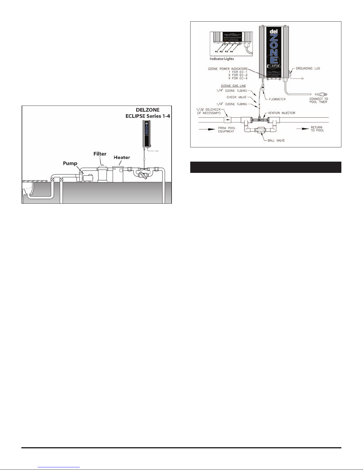
4A-1. Indicator Lights (LEDs):
1. Ozone Power: The green indicator light(s) on the front of
the DELZONE®Eclipse indicate(s) that the ozone power
supplies are operating properly. The EC-1, EC-2, and EC-4
should show 1, 2, and 4 green "ozone power" indicator
lights, respectively. NOTE:If any of the lights turns red, it
means that the ozone generating module has failed. Con-
tact DEL Ozone customer service at 805.541.1601 if your
unit is still under warranty. If none of the indicator lights are
on, it means that there is no power to the unit. Check the
power connections and/or the fuse
4A-2. Internal Components: Ozone Module: Each ozone
module consists of a power supply connected by two high
voltage wires to an electrode.
4B System Maintenance
4B-1. The green "ozone power” indicator light(s) on the front
of the DELZONE®Eclipse indicate that the ozone power supply
is operating properly. When an indicator light turns red, replace
the corresponding ozone module.
4B-2. Each ozone module should be replaced after 15,000
hours of operation*. Even if the green indicator light(s) are
glowing, the ozone module may be producing little or no ozone
after this period of time due to material degradation within the
corona discharge ozone chamber.
*15,000 hours equals approximately 5 years if the pool system
operates8hours/day365daysoftheyear,orapproximately2years
if the pool system operates 24 hours/day 365 days of the year.
4B-3. Regularly check the owmeter for proper ow and
inspect ozone supply tubing for cracks or wear. Replace ozone
supply tubing as necessary.
4B-4. Replace "ozone check valve" (replacement part number
7-1140-01) every 15,000 hours, or sooner if needed.
WARNING:DoNOTtouchtheendsofthecheckvalvewhen
replacing.Traceamountsofnitricacidmaybepresentonthe
checkvalveandcouldproveharmfuliftouchedoringested.
4B-5. While operating, check to see if bubbles are entering the
pool (unless you have installed an MDV to remove bubbles).
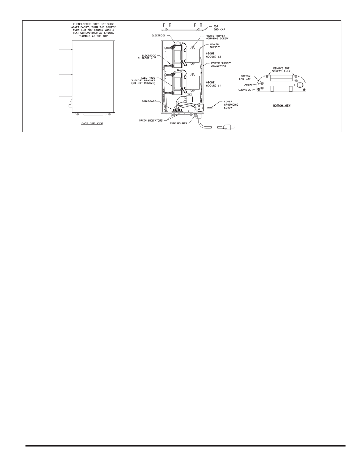
4C Generator Servicing - Refer to Figure 4
4C-1. The DELZONE®Eclipse ozone generator must be removed
from the wall before servicing. To remove the Eclipse:
1. Make sure the power is off by disconnecting the power
cord from the pool timer circuit.
2. Disconnect the ozone supply tubing from the bottom end
cap of the Eclipse.
3. Disconnect ground wire.
4. Remove the four wall mounting screws.
4C-2. Opening the Eclipse
The DELZONE®Eclipse enclosure consists of two aluminum
plates that slide together. They are held in place by the plastic
end caps. To open the enclosure:
1. Lay the DELZONE®Eclipsefaceuponahard,atsurface.
2. Remove the Top End Cap completely by removing the four
screws. Remove only the top two screws of the bottom end cap.
3. Remove the cover grounding screw located on the lower
right side of the unit.
4. Carefully slide the two enclosure halves apart by gripping the
BaseEndCaprmlyandpullingontheEnclosureCover.
NOTE: If the two halves do not slide apart easily, turn the
DELZONE®Eclipseoveranduseascrewdrivertoprythecover
offasshowninFigure4.
4C-3. Ozone Module Replacement
The EC-1, EC-2, and EC-4 have 1, 2, and 4 ozone modules,
respectively. The green indicator lights on the front of the
DELZONE®Eclipse correspond from left to right to ozone
module number 1 through 4. For the EC-2 and EC-4, the ozone
modules are numbered beginning with number 1 at the bottom.
To replace an ozone module:
1. Open the DELZONE®Eclipse as described in section 4C-2.
2. Disconnect the tubing at both the inlet and outlet of the
ozone electrode.
3. Remove the two nuts that secure the ozone electrode to
the support bracket.
4. Disconnect the plastic power connector between the power
supply and wire harness.
5. Remove the two screws that secure the power supply to
the metal base.
6. Install the new ozone module by reversing the above steps.
DELZONE®Eclipse 1, 2, & 4 Corona Discharge Ozone Generators
3

Figure 4 Component Locations (Eclipse-2 Shown). Additional transformers are used on 240V models, which are not shown in this diagram.
4D. Trouble Shooting
Knowledge of electrical applications is required for trouble shoot-
ing. Contact a certied electrician if you are unsure of your ability to
service the equipment. Improper servicing will void generator war-
ranty. If any condition persists, call DEL at 800-676-1335, ext. 248
for technical assistance or visit our website at www.delozone.com.
Symptom: “LED Indicator” not lit when pool system is on.
1. No power to the ozone generator from the power source:
a. Check circuit breaker at the power distribution box.
b. Check for loose connections or wiring breaks from the
power distribution box to the generator.
c. Fuse in the unit has blown and needs to be replaced.
2. G.F.C.I. has tripped.*
a. Check power cord and reset G.F.C.I. (*If G.F.C.I. or
breaker continues to trip after reset, call 1-800- 676-
1335, ext 248 for technical assistance).
Symptom: Flowmeternotindicatingow.
1. Injector not supplying adequate suction.
a. Checkpumpandensurewaterisowingthroughinjector.
b. Checkby-passvalve andadjustif necessaryto obtainproper
pressure differential in order to reestablish suction.
c. Check that injector is plumbed in the right direction.
d. Ensure that there is no debris clogged inside the injector.
2. Tubing is impaired.
a. Check for kinks or clogs.
b. Check for cracks or cuts.
c. Check connections.
d. Check that the check valve is installed with the arrow
pointing towards the injector.
e. Be sure that the check valve has not become fouled with
debris. Disconnect the ozone tubing from the ozone gen-
erator and the check valve. With the pump running, test
the end of the ozone tubing with your thumb, and feel
for suction. Wash your hands immediately afterwards
to remove any residual nitric acid that may be on the
tubing.Ifthereissufcientsuctionwithoutthecheck
valve, replace the check valve with a new one.
Symptom: LED Indicator has turned red.
a. Thismeansthatthepowersupplyofthatspecicozone
module is no longer drawing power and needs to be
replaced. Inside the Eclipse the modules are numbered
from the bottom up. So on an Eclipse 4, the top ozone
module is #4 and the bottom ozone module is #1. These
correspond to the LED ozone indicators at the bottom of
the Eclipse, numbered 1-4 from left to right. This should
tell you which ozone module has failed. Refer to section
4C3 for instructions on how to replace the correspond-
ingozonemodule.Ifyouarehavingdifculties,contact
Del’s service department at 1(800)676-1335 ext. 248.
Note: it is normal for the LED indicators to shine red for
several seconds as the system powers up. As long as they
turn back to green several seconds after startup. This is
caused by the electronics charging up to create ozone.
Symptom: Ozone tubing becomes yellow/brown and brittle.
a. The high concentration of ozone created by the DELZONE
Eclipse family of corona discharge ozone generators ,
as well as environmental conditions like UV sunlight will
tend to deteriorate the supplied ozone tubing. This is
normal and acceptable, as long as the tubing doesn’t
become cracked and leak. Because of this, DEL rec-
ommends replacing the ozone supply tubing and your
check valve every year. More ozone tolerant tubing is
available through DEL, however, it is still required that
you change your check valve annually.
Symptom: Cant get ball to stay on centerline of owmeter.
a. The flowmeter provided is a general tool to setup
owtotheozonegenerator.Flowwillvarydepending
on pressures across the injector, and therefore can
be affected by things such as lter or strainer load-
ing. The ozone generator’s efciency is optimized at
near the centerline of the ow meter. However, the
DELZONE Eclipse ozone generator will still perform
quitewellatowsaboveandbelowtherecommended
range. As long as the ball is moving, and not stuck
on the bottom of the owmeter, you should be ne.
DELZONE®Eclipse 1, 2, & 4 Corona Discharge Ozone Generators
4

DELZONE®Eclipse 1, 2, & 4 Corona Discharge Ozone Generators
SECTION 5 Replacement Parts and Order Information
5A. Ordering information: 5B. Standard replacement parts list:
1. Ozone Module ............................................. 5-PA0213*
2. Ozone Check Valve, 1/4" x 1/4" ............... 7-1140-01*
3. Tubing, 1/4" Ozone Line ..................................7-0075*
*Items 2and 3should be checked & replaced concur-
rently, once a year.
To locate a dealer nearest you call DEL at 1-800-676-1335,
ext 249 or visit www.delozone.com.
Be prepared with the following information:
•Name •Address
•DEL Model # •Date Purchased
DEL Ozone
LIMITED ONE YEAR WARRANTY
The limited warranty set forth below applies to products manufactured by DEL Ozone - 3428 Bullock Lane, San Luis Obispo, Cali-
fornia93401,andsoldbyDELOzoneoritsauthorizeddealers.Thislimitedwarrantyisgivenonlytotherstretailpurchaserof
such products and is not transferable to any subsequent owners or purchasers of such products.
DEL Ozone warrants that it or its authorized dealers will repair or replace, at its option, any part of such products proven to be
defective in materials or workmanship within ONE (1) year from the date of retail purchase of such products. (All parts) ANY REPAIR
OR REPLACEMENT WILL BE WARRANTED ONLY FOR THE BALANCE OF THE ORIGINAL WARRANTY PERIOD. NOTE: USE ONLY DEL
Ozone AUTHORIZED REPLACEMENT PARTS. USE OF ANY OTHER PART(S) WILL AUTOMATICALLY VOID THIS WARRANTY.
THIS LIMITED WARRANTY DOES NOT INCLUDE ANY OF THE FOLLOWING: (a) any labor charges for troubleshooting, removal, or
installation of such parts; (b) any repair or replacement of such parts necessitated by faulty installation, improper maintenance,
improperoperation,misuse,abuse,negligence,accident,re,repairmaterials,and/orunauthorizedaccessories;(c)anysuch
products installed without regard to required local codes and accepted trade practices; (d) ANY IMPLIED WARRANTY OF MERCHANT-
ABILITY OR IMPLIED WARRANTY OF FITNESS FOR PARTICULAR PURPOSE, AND SUCH WARRANTIES ARE HEREBY DISCLAIMED: AND
(e) DEL Ozone SHALL NOT BE LIABLE UNDER ANY CIRCUMSTANCES FOR LOSS OF USE OF SUCH PRODUCTS, LOST PROFITS, DIRECT
DAMAGES, INDIRECT DAMAGES, CONSEQUENTIAL DAMAGES AND/OR INCIDENTAL DAMAGES.
TO OBTAIN WARRANTY SERVICE
Contact: DEL Ozone · 3428 Bullock Lane · San Luis Obispo, CA · 93401
Customer Service Number : (805) 541-1601
Whenlingaclaim,youmustprovide:
1. your name, mailing address and telephone number
2. the selling dealer’s name
3. proof of date of purchase
4. the date of failure
5. a description of the failure
After this information is provided, DEL Ozone will release a RETURN GOODS AUTHORIZATION (RGA) NUMBER. After receiving
the RGA number the part in question must be returned to DEL Ozone, freight prepaid, with the RGA number clearly marked on the
outside of the package. All preauthorized defective parts must be returned to DEL Ozone within thirty (30) days. Under no circum-
stances may any product be returned to DEL Ozone without prior authorization. You must call or write DEL Ozone prior to returning
product or your returned goods shipment will be refused. Upon receipt of preauthorized returned goods, DEL Ozone will repair or
replace, at DEL Ozone’s option, the defective product(s) and return them freight (prepaid for products under warranty). Buyer’s
acceptance of the product and use thereof constitutes acceptance of these terms.
5

This manual suits for next models
2
Table of contents
Other Del ozone Lighting Equipment manuals
Popular Lighting Equipment manuals by other brands

ESI
ESI Amble Classic Operation instructions

Universal Laser Systems
Universal Laser Systems US1301 Series installation instructions

Lyyt
Lyyt 155.010UK installation guide

Daintree
Daintree GE Tetra Atom installation guide

Lightolier
Lightolier Mini-Beam Mini-Beam Luminaires user manual

delight smart solutions
delight smart solutions 55852D User manual and installation guide