ii
Finisher Service Manual
Version 1 2009.03.31
1. About this manual
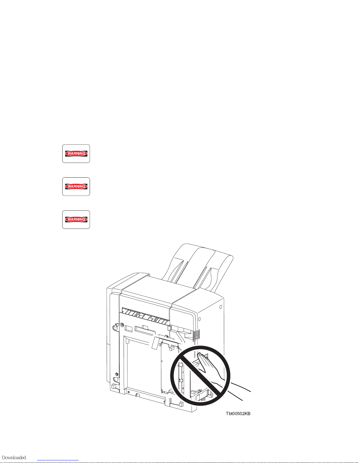
2. Marks giving caution
Maintenance operations requiring special cautions or additional information regarding descriptions in
this manual are presented as "Warning," "Caution," or "Note," depending on their nature.
If instructions are not observed, death or serious injury may result.
If instructions are not observed, injuries to workers or physical damage to assets
(including this finisher) may result.
Essentials for procedures, steps, rules, and others.
Reference Incidental information to descriptions.
3. Related documents
-Instruction manuals (standard manuals)
Describe the operation and handling of this finisher.
-Performance specifications
Describe in detail various specifications of this finisher.
(In the event of a discrepancy between this manual and the performance specifications, the
performance specifications take precedence.)
-Spare parts list
Information on maintenance parts (spare parts) for this finisher.
This manual is a standard service manual of
Dell Inc.
containing information
required for maintenance
of this finisher.