DELLON GM Series User manual
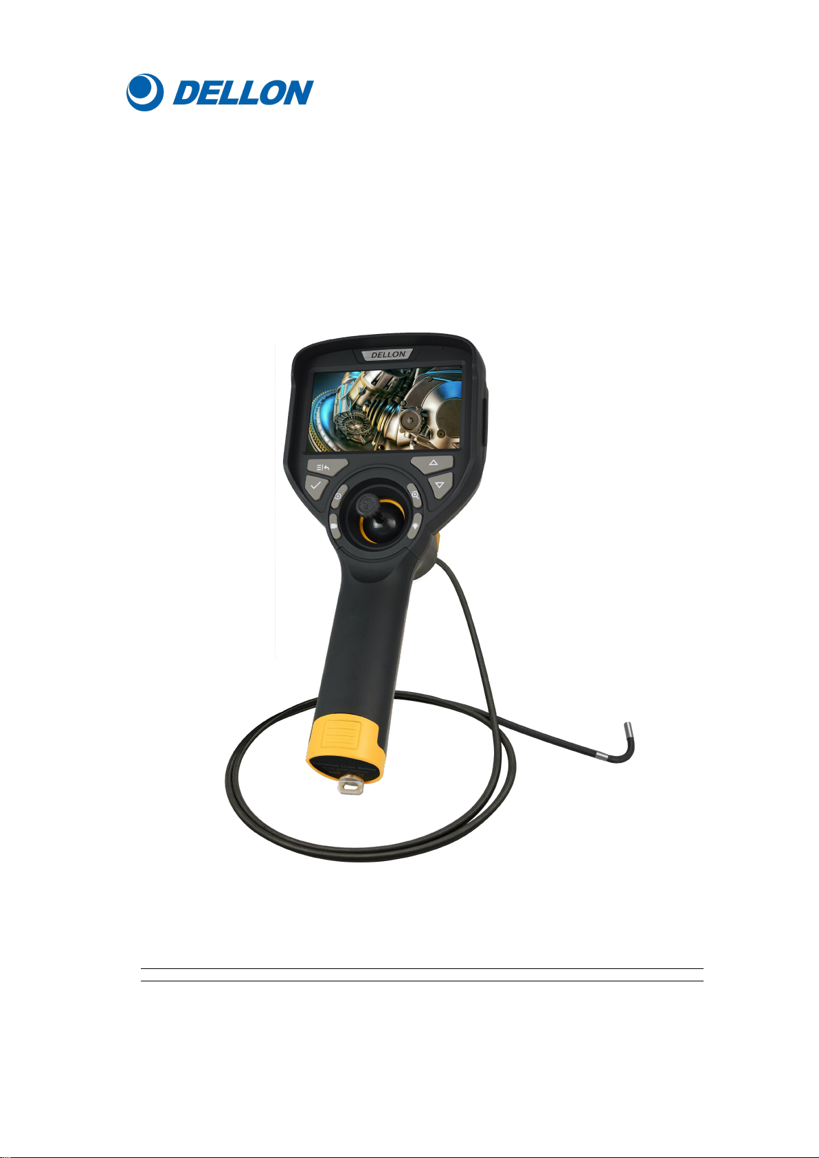
GM Series Industrial Videoscope
Operation Manual
■Please read this operation manual carefully before using the product.
■Please keep it in a safe place for future reference.

1
Thanks for purchasing our G-Mini series videoscope, if it is your first time
to use the videoscope, please read this operation manual carefully in order to
better and safer to use this product.
Contents
Product introduction ..................................................................................................... 2
Hardware introduction ..................................................................................................3
Operation ...................................................................................................................... 8
Software interface operation .........................................................................10
System settings ............................................................................................. 14
Main Accessories ........................................................................................................29
Product parameters ..................................................................................................... 30
Simple troubleshooting ...............................................................................................32
Precautions ................................................................................................................. 32
After-sales service ...................................................................................................... 33
1. Service commitment .................................................................................33
2. Out-of-warranty liability .......................................................................... 33
3. Fault maintenance period ......................................................................... 28
2
Product introduction
G-Mini series industrial videoscope (as shown above) is a new nondestructive
testing instrument which integrates the technology of optics,electronic technique,
precision machinery and photomicrography.
○Optics inspection
The controller is equipped with high brightness LCD display, an ultra-small camera
and the video signal is processed and amplified to clearly display the detection
results on the 4.3 inches LCD display. It has high definition, high reliability, high
stability, excellent field detection capability.
○Precision machinery
The bending part is made up of machinery parts, manual operation, 360°all-way
articulation,at the same time it has the function of self-locking, and easy to operate
with one hand.
○Applications
This product is suitable for video inspection in small space, and can visually detect
foreign objects, blockages and defects inside automotive engine( cylinder, piston,
valve and other carbon deposit detection) hydraulic, pneumatic parts, steel pipes,
castings and containers; it can also be used for anti-terrorism, search and other small
entrance peep inspection.
○Product features
High pixels: High resolution camera provides better picture quality; High sensitivity
CMOS sensor ensures the observation in low light conditions.
Camera: Adopt high brightness LED source, 720P high pixel CMOS.
Storage display: With the function of storing data such as photography and video,
equipped with 32GB SD card.
Replaceable Probe: Interchangeability design of controller and probe, the 3.9mm/
6.2mm probe with different diameters and lengths can be quickly replaced to apply to
more working conditions.
Touch screen key and function key: Touch screen and key dual operation control
system, can quickly achieve recording, file access, parameter setting, etc.
3
Hardware introduction
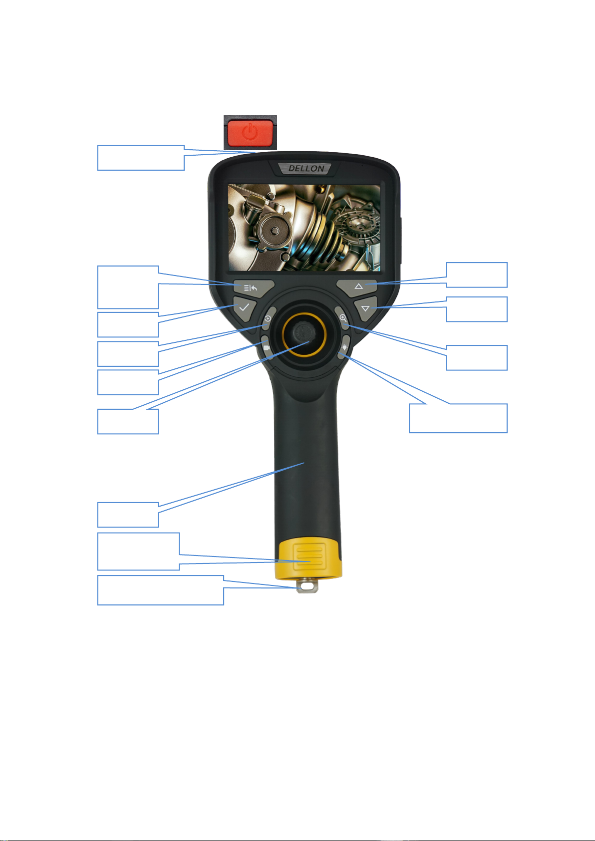
Front of controller
Power on/off button: Click the button to power on, press and hold the button for 2
seconds to power off.
Menu/return button: Press menu/return button to switch between the real-time
screen and the menu mode; In menu mode, press this key to return to the previous
interface.
Ok button: When selecting menu options, press this button to confirm.
Replay button: Switch between real-time screen and file preview, exit the current
state in picture view/ video playback state. Return to the preview list, and return to
Zoom
Light adjustment
Menu/
return
OK
Replay
Video
Up
Power on/ off
Battery cover
Joystick
Probe
Battery locking screw
Down

4
the real-time screen state in the preview list state.
Video button: In the real-time picture state, press this button to start recording, and
to press it again to stop recording.
Joystick: Control the bending part moving, achieving comprehensive inspection.
Up button: Press this key to move the cursor forward during menu setting.
Down button: Press this key to move the cursor backward during menu setting.
Zoom button: Image cycle zoom.
Light adjustment button: 5 levels of lens light gradually from dark to bright cycle
adjustment.
Side of the controller
Type-C interface: This interface is a charging port, can also be a data
communication port. This interface can connect to the computer, browse, access the
video and picture files in the TF card.
HDMI interface: Through the HDMI interface, the image detected by videoscope
camera can be displayed on the external monitor in real time.
Note: When the external monitor is connected, just connect the video output
port and the external monitor with the video cable to display the real-time
picture from the probe on the monitor. At this time, the screen of videoscope is
black.
Headphone interface: This is the audio output interface.
TF card slot: This is the TF card installation interface for device storage expansion.
Camera button: In real-time mode, press this button to take picture and store it at
the same time.
Type-C interface
TF card reader
HDMI interface
Camera button
Handle locking screw
Headphone
interface

5
Insertion cable and lens
Insertion cable: IP67 waterproof.
Bending part: It is controlled by joystick, 4-way articulation.
Equipment assembly
1.Assemble the controller and probe
Bending part
Insertion cable
1.Joystick is aligned
with the joystick hole
in the controller.

6
4.Tighten the
locking screw.
Hook
Slot
2.The hook on the host
is aligned with the slot
of probe, and press it
tightly.
3.Shown as above, the
controller and the probe
is assembled in place.

7
2.Battery installation
3. Interface side cover
When closing the side cover as shown in the figure, first push the two straps on the
side cover into the strap holes, and then buckle the side cover.
1.Unscrew the battery locking
screw and remove the handle cover.
4. Tighten the locking screw
clockwise.
3. First put the handle cover on the
buckle into the end of the handle, and
then press the handle cover tightly.
2. Put the positive pole of
the battery into the handle.
Battery negative
Battery positive

8
Operation
1. When using, first confirm that the videoscope has installed the battery and TF
card, and press the power on/off button to turn on the controller.
2. Observe objects.
a.Press the light adjustment button to turn on the LED light;
b.Insert the probe into the observation body to reach the observation position;
c.The articulation part is adjusted by controlling the joystick so that the probe
reaches the target orientation;
d. Adjust the LED brightness and the zoom key to adjust the magnification to
achieve the best results in the live view.
Note:When inserting the probe into the observation body, first make sure
that the articulation part is adjusted to be straight to avoid probe damage.
3. After the observation position is aligned, the testing results can be recorded and
stored through the function buttons.
Confirm that the controller is in image mode, press the camera key at this time to
take pictures, the video key can record the video, and then press the video button
to stop recording;
Photo mode Video mode
Menu mode

9
4. Live image status:
a.Press the magnification key to cycle the image to 5x magnification;
b.Press the light adjustment button to adjust the light brightness to achieve the
ideal display effect;
5. After the observation is completed, the articulation part is adjusted to straighten,
and then safely exits the observation body and then shuts down.
6. Instrument storage:
Cover the probe with a protective cap to avoid damage to the
internal precision parts; Wipe off the obvious stains on the device with a wipe,
remove the battery, and place it separately in the instrument case.
(Note: When storing the videoscope, make sure that the articulation part is
straight before coiling the cable in the box.)

10
Software interface operation
In the real-time mode, tap the screen to bring up the main interface, the main
interface is divided into the status bar, function menu and monitoring screen display
area, and tap the blank area of the screen again to close the main interface:
(In addition to the touch screen mode, the screen operation can be controlled
by menu/back button, confirmation button, playback button, video button, up
button, down button, magnification button and other buttons.)
1.Status bar
The status bar is used to display the usage status of the device, such as: time, image
magnification, temperature icon, image rotation status (R), LED light brightness
level, WIFI status, TF card status, battery status.
Temperature icon--Used to indicate the temperature of the probe, the color of the
picture changes sequentially as the temperature changes, .
Image rotation state (R)--Used to indicate the image display state, when the image
rotates, indicating that the icon changes.
LED brightness level--Used to indicate the current working level of LED lights, a
total of 5 levels of change, icon also shows the corresponding number of levels.
Monitoring screen area for displaying real-time images of endoscope transmission.
11
2.Menu
Tap the menu icon , enter the menu setting interface, which contains 6 sub
menus: image settings, display settings, application settings, system settings,
playback, WIFI.
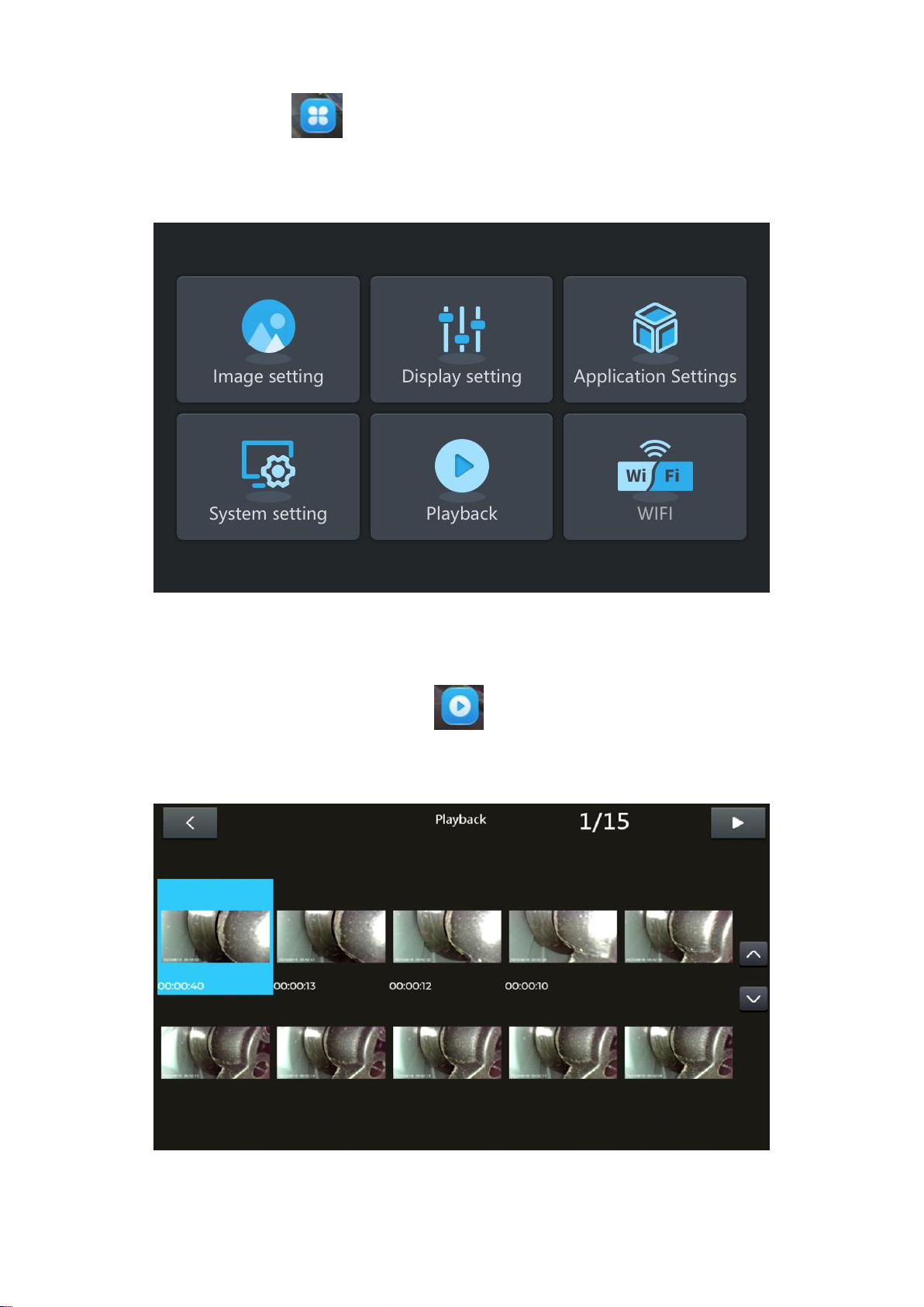
3.Playback
Click the icon on the main interface ,the software will leave the current
monitoring screen and enter the file management page, where you can view and
manage the recorded audio and video.

12
4.Image settings
Click the Image settings icon ,the main interface pops up the setting options of
the image. On this page, you can set the image contrast one after the other ,image
brightness ,image tone ,image sharpness ,click the confirmation button or
to save the settings. Click to restore default parameters. Adjust by scrolling
bar, and fine-tune the symbols on both sides.

13
5.Watermark
Click the watermark icon ,the text input box appears on the interface, click the
text input box, you can enter the specified text in the text input box. Then click on
icon to confirm.
6.Grid
Click the grid icon ,
the main interface will appear in turn, cross ruler, ring ruler,
no ruler, three states, the grid floats above the screen. After taking a photo, it can be
superimposed on the image file.
14
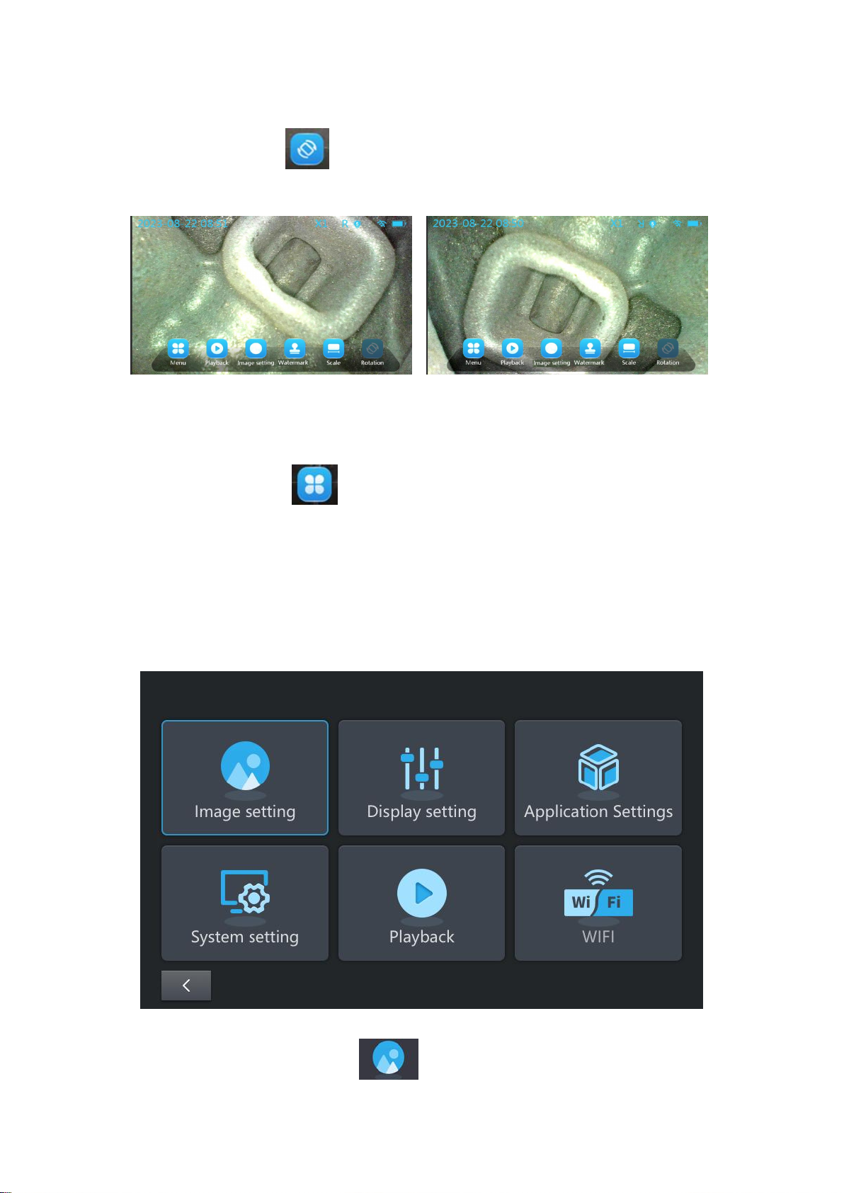
7.Rotate
Click the rotation icon ,image will rotate from to 0° to 180°. The "R" icon in
the status bar displays the rotation angle of the current monitoring screen.
System settings
Press the menu button on the screen to enter the menu setting interface, as
below figure shows, there are 6 first-level menus: image setting, display setting,
application setting, system setting, playback, WIFI.
Remarks: After selecting to enter, click or drag the corresponding icon and
press the confirmation key to confirm.
All the functions of the icons in the figure below are the same and synchronized with
those of the icons with the same name in the main interface.
1.Image settings
After entering the image setting interface, you can set parameters such as

15
image contrast, image brightness, image tone, image sharpness. After adjusting the
parameters, click to save.
2.Display settings
After entering the display setting interface. In this interface, you can set
image rotation, display brightness, rulers, and watermark annotations. After adjusting
the parameters, click to save.
Rotation display, click icon, screen rotates for 180°; click image left and
right mirroring; click , image up and down mirroring; click the image
comes to original position.
16
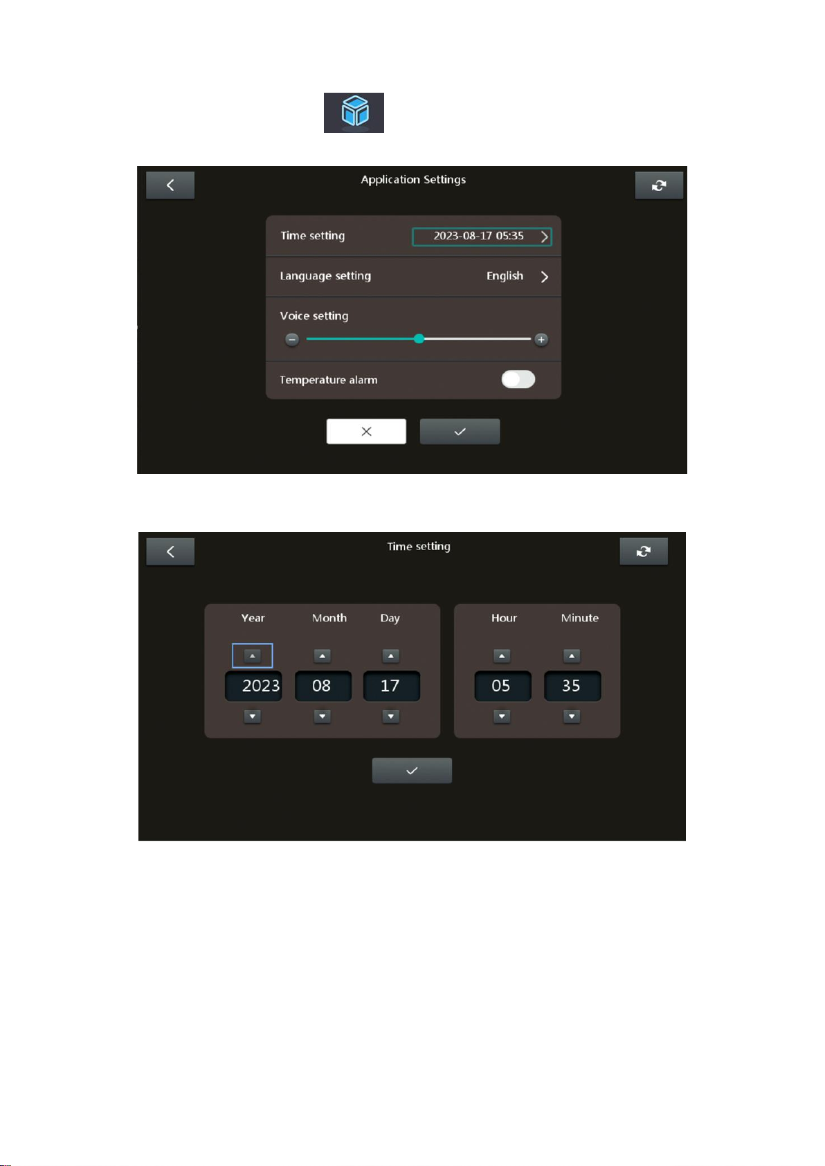
3.Application settings
Enter the application setting interface, you can set time, language, sound,
temperature alarm and other functions.
A: Time settings
Click to enter the time setting sub-menu to set the year/month/day/hour/minute.
17
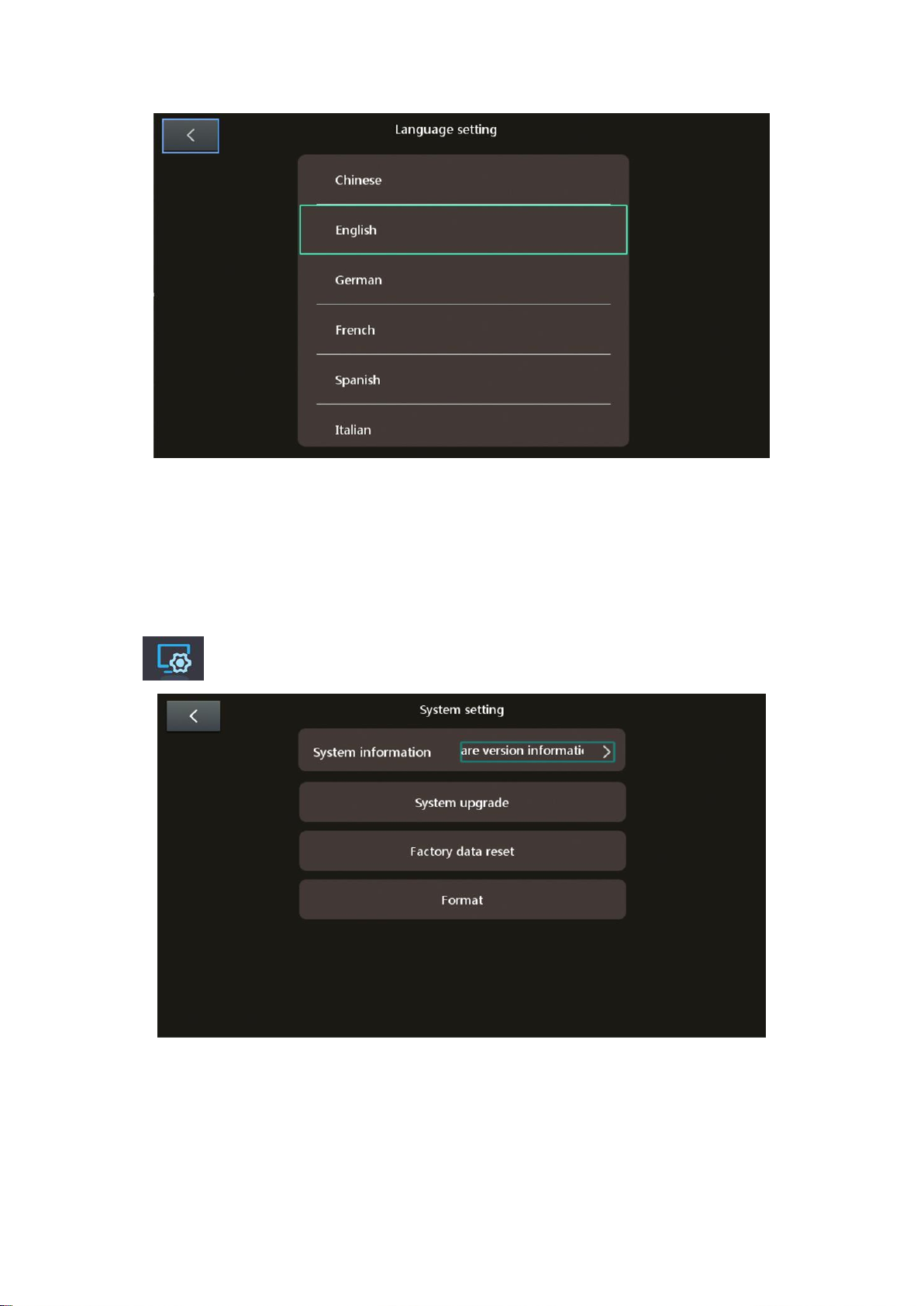
B: Language settings
Click to enter the language setting menu, 10 languages can be selected and set.
C: Sound settings
Touch or drag the light bar to adjust the playing sound volume of the controller.
D: Temperature alarm
Touch the icon on the right side of the temperature alarm to turn on the temperature
alarm function. When the temperature of the probe itself rises or the external
temperature reaches a critical point, the device will alarm.
4.System settings
Enter the system setting interface:

18
A: System information: Click system information to view the software version
information.
B: System upgrade: Install the new software in the TF card and insert it into the
device, click the icon to pop up the corresponding warning box to choose whether to
upgrade, and ensure that the device cannot be powered off during the upgrade
process.

19
C: Restore factory settings: Click this icon to pop up a corresponding warning box to
choose whether to restore factory settings.
D: Format: Click this icon to pop up a corresponding warning box to choose whether
to format the memory card.
Table of contents
Other DELLON Analytical Instrument manuals


