4 Replacement procedures
4 INF12/113–EN Rev. C | Navigator 550 | Low level dissolved oxygen wet-section | Spares replacement procedures
4.3 Replacing the flowmeter assembly
Part number: AW502 060
Flowmeter assembly: AW502 060
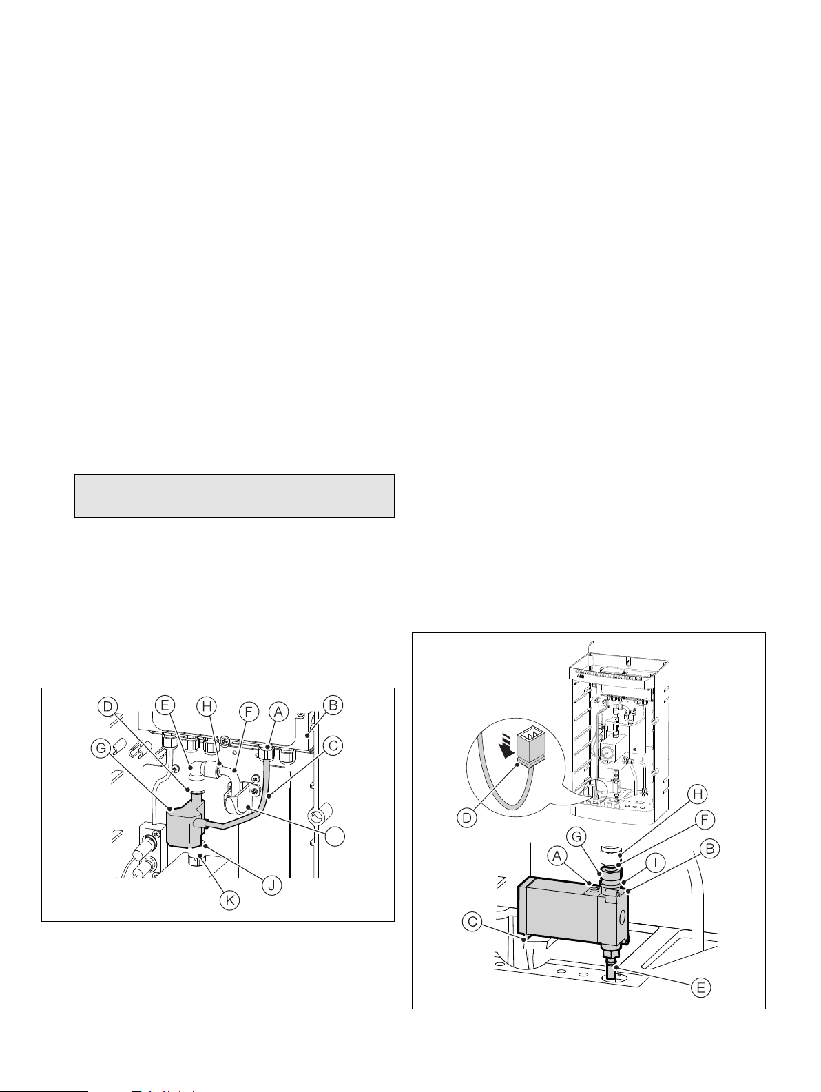
Referring to Fig. 4.6:
1. Depress the manual override button Aon the drain valve
assembly to drain the wet-section.
2. Remove the wet-section PCB cover as detailed in step 1 of
Section 4.1, page 3.
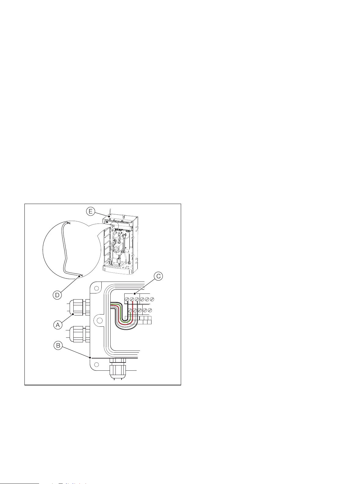
Referring to Fig. 4.5:
3. Loosen cable gland Aat the wet-section PCB housing B.
4. Disconnect the flowmeter cable Cfrom wet-section PCB
terminals 13 (red, +ve), 15 (brown, GND) and 17 (black –ve) –
see Fig. 4.3, page 3 and remove cable.
5. Depress the QD coupling collar Don QD coupling Eand
lift the top QD coupling Ecomplete with sample outlet tube
Faway from the flowmeter G.
6. Depress the QD coupling collar Jon QD coupling Kand
lift the flowmeter away.
7. Fit the replacement flowmeter into the QD coupling Kand
refit QD coupling Eto the flowmeter outlet.
8. Pass the flowmeter cable through the cable gland Aat the
wet-section PCB housing Band terminal connections to
PCB terminals 13 (red, +ve), 15 (brown, GND) and 17 (black
–ve) – see Fig. 4.3, page 3.
9. Refit the PCB cover as detailed in step 11, Section 4.1,
page 3.
10. Ensure the sample outlet tube Fis located correctly in the
tundish assembly I.
4.4 Replacing the drain valve assembly
and drain valve cable assembly
Part numbers:
Drain valve assembly: AW502 056
Drain valve cable assembly: AW502 085
Referring to Fig. 4.6:
1. Depress the manual override button Aon the drain valve B
to drain the wet-section.
2. Disconnect the clip-on cable connector Cfrom the end of
the drain valve coil housing by depressing the clip D.
3. Disconnect the drain tube from the barbed outlet connector
Eon the bottom of the drain valve B.
4. Lock hex coupling Gand rotate nut Hclockwise to release
couplings. Remove the valve assembly, complete with
coupling G. Remove coupling Gfrom the valve assembly
and fit to new valve, complete with new bonded seal I.
5. If fitting a new drain valve cable assembly, remove the
wet-section cover as detailed in step 1 of Section 4.1, page 3
and loosen the drain valve cable gland in the wet-section PCB
housing and proceed with steps 7, 8 and 9 below.
If using the existing cable, re-connect the clip-on cable
connector Cto the end of the drain valve coil housing.
6. Disconnect the drain valve cable from the terminal block – see
Fig. 4.3, page 3 and discard the cable.
7. Feed the replacement drain valve cable through the cable
gland and make connections to the black, red, screen, green
and white PCB wet-section terminals (see Fig. 4.3, page 3)
and at the transmitter (see OI/ADS550-EN).
8. Connect the drain valve clip-on cable connector Cto the
end of the drain valve coil housing.
Note. The orientation of the flow arrow on the flowmeter
must be upwards.
Fig. 4.5 Replacing the flowmeter assembly and flowmeter cable
Fig. 4.6 Replacing the drain valve assembly and drain valve cable