manuals.online logo
Brands
  1. Home
  2. •
  3. Brands
  4. •
  5. Delta Electronics
  6. •
  7. Other
  8. •
  9. Delta Electronics DNA02 User manual

Delta Electronics DNA02 User manual

http://www.delta.com.tw/industrialautomation/
5011649001-NAE1
2007-05-24
DeviceNet Slave Station Communication Module
Instruction Sheet
Warning
Please read this instruction carefully before use and follow this instruction to operate the device in order to prevent
damages on the device or injuries to staff.
Switch off the power before wiring.
This instruction sheet only provides introductory information on electrical specification, functions, wiring,
trouble-shooting and peripherals for DNA02. Details of DeviceNet protocol are not included in this sheet. For more
information on DeviceNet Protocol, please refer to relevant reference or literatures.
DNA02 is an OPEN-TYPE device and therefore should be installed in an enclosure free of airborn dust, humidity,
electric shock and vibration. The enclosure should prevent non-maintenance staff from operating the device (e.g. key or
specific tools are required to open the enclosure) in case danger and damage on the device may occur.
DNA02 is to be used for controlling the operating machine and equipment. In order not to damage it, only qualified
professional staff familiar with the structure and operation of it can install, operate, wire and maintain it.
DO NOT connect input AC power supply to any of the I/O terminals; otherwise serious damage may occur. Check all
the wiring again before switching on the power and DO NOT touch any terminal when the power is switched on. Make
sure the ground terminal is correctly grounded in order to prevent electromagnetic interference.
Introduction
1.1 Model Explanation
Thank you for choosing Delta DNA02 DeviceNet communication module. DNA02 can be applied to the connection
between DeviceNet and Delta’s programmable logic controllers, AC motor drives, servo drives, temperature
controllers and DOP human machine interfaces. In addition, DNA02 offers custom function, which can be applied
to the connection between DeviceNet and self-defined equipments with Modbus protocol.
Features
Supports Group 2 only servers
Supports explicit connection in the pre-
defined
master/slave connection group
Supports polling
Supports EDS files in DeviceNet network configuration
tools
Nameplate explanation
MODEL :
POWER INPUT :
DNA02000T7020022
VX.XX
DNA02
24Vdc 2.0W
DELT A ELE CTR ONI CS, IN C MA DE IN X XXX XXX
Model name
Power input spec.
Barcode & serial No.
Ver sion
Serial No. explanation
Production No.
Production week
Production year (2007)
Production plant (W: Wujiang T: Taoyuan)
Version No.
Model name
1.2 Product Profile and Outline
1
23
4
5
6
7
8
9
10
Unit: mm
1
Communication port
2
Address setup rotary switch
3
Function setup DIP switch
4
Instruction on function
setup switch
5
SP (Scan Port) indicator
6
MS (Module Status) indicator
7
NS (Network Status) indicator
8
DeviceNet connector
9
DIN rail

DIN rail clip
Specifications
DeviceNet Connector
Type Removable connector (5.08mm)
Transmission method CAN
Transmission cable 2 communication cables, 2 power cables and 1 shielded cable
Electrical isolation 500V DC
Communication
Message type I/O polling; explicit
Series transmission speed
125 Kbps; 250 Kbps; 500 Kbps
Equipment type 12
Company ID 799 (Delta Electronics, Inc.)
Electrical Specifications
Voltage: 11 ~ 25V DC (offered by the power cable in the network)
DeviceNet Current: 28mA (typical), 125mA impulse current (24V DC)
Environment
Standards IEC 61131-2, UL508
Storage/Operation Storage: -25°C ~ 70°C (temperature), 5 ~ 95% (humidity)
Operation: 0°C ~ 55°C (temperature), 50 ~ 95% (humidity); pollution degree 2
Shock/Vibration
immunity
International Standards: IEC61131-2, IEC 68-2-6 (TEST Fc)/IEC61131-2 & IEC 68-2-27
(TEST Ea)
Interference immunity
RS (IEC 61131-2, IEC 61000-4-3): 80MHz ~ 1,000MHz, 1.4GHz ~ 2GHz, 10V/m
EFT (IEC 61131-2, IEC 61000-4-4): Analog & Communication I/O: 1KV
ESD (IEC 61131-2, IEC 61000-4-2): 8KV Air Discharge
Certificates CE, UL
Components
3.1 DeviceNet Connector
To connect with DeviceNet network, use the connector enclosed with DNA02 or any connectors you can buy in the
store for wiring.
PIN Signal Color Description
1 V- Black 0 VDC
2 CAN_L Blue Signal-
3 SHIELD - shielded cable
4 CAN_H White Signal+
5 V+ Red 24 VDC
1
2
3
4
5
3.2 Address Setup Rotary Switch
The two rotary address setup switches set up the node addresses on
DeviceNet network in decimal form. Setup range: 00 ~ 63 (64 ~99 are
forbidden)
5
0
x10
1
0
x10
5
0
Example:
If you need to set the node address of DNA02 as 26, simply switch the corresponding rotary switch of X101 to “2”
and the corresponding rotary switch of X100to “6”.
Address Setting
Description
0…63 Valid DeviceNet
communication address
Others Invalid DeviceNet
communication address
The changed values on switches are only valid
when DNA02 is re-powered. When DNA02 is
operating, changing the set value of
communication address is invalid.
3.3 Function Setup DIP Switch
The DIP switch is to be used on the equipment connected to DNA02,
the selection of communication ports and setting up the
communication speed of DNA02 and the master station in DeviceNet.
1234
5678
SW3
DIP
ON
3.3.1 Selecting Equipment Connected to DNA02
PIN 1 PIN 2 PIN 3 Equipment
ON OFF OFF AC motor drive
OFF ON OFF Programmable logic controller
ON ON OFF Temperature controller
OFF OFF ON Servo drive
ON OFF ON Human machine interface
OFF ON ON Custom equipment
ON ON ON For internal system use
Example:
If the equipment connected to DNA02 is Delta servo drive, you only need to switch PIN 3 to “On”, PIN 1 and PIN 2
to “OFF” and re-power it.
The changed setting of the switch is only valid when DNA02 is re-powered. When DNA02 is operating, changing the
setting of DIP switch is invalid.
3.3.2 Selecting DNA02 Communication Mode
PIN 4 PIN 5 Communication Mode
OFF OFF RS-485
ON ON RS-232
ON OFF
OFF ON
Incorrect setting
The changed setting of communication mode is only valid when DNA02 is re-powered. When DNA02 is operating,
changing the setting of communication mode is invalid.
3.3.3 Setting up Baud Rate
PIN 6 PIN 7 PIN 8 Slave Device Baud Rate
OFF OFF 125K bps
ON OFF 250K bps
OFF ON 500K bps
ON ON
Reserved
Auto baud rate detection
The changed setting of the baud rate of DeviceNet is only valid when DNA02 is re-powered. When DNA02 is operating,
changing the communication speed is invalid.
3.4 Communication Ports on DNA02
The communication ports on DNA02 are used for connection with
equipments (Delta PLC, Delta AC motor drive, Delta temperature
controller, Delta servo drive, Delta human machine interface and
custom equipments)
PORT1
PORT2
3.4.1 PORT1
PORT1 PIN definition
PORT1 Sketch Terminal No. Description
1 N.C.
2 GND
3 DATA-
4 DATA+
5 N.C.
1
2
3
4
5
6
PORT1
6 N.C.
PORT1 supports RS-485 communication mode only.
3.4.2 PORT2
PORT2 Sketch Terminal No. RS-232 RS-485
1 N.C. N.C.
2 RXD N.C.
3 TXD DATA-
4 N.C. N.C.
5 GND GND
6 N.C. N.C.
7 N.C. N.C.
8 N.C. DATA+
1
6
2
7
3
8
4
9
5
DB9 male
9 N.C. N.C.
PORT2 supports RS-232 and RS-485 communication mode only.
Connectors for DNA02 and the Equipments
See below communication wiring when DNA02 is connected to an equipment through PORT1.
When connected to Delta AC motor drive When connected to Delta PLC
RS-485 communication mode
(Using standard cable with RJ-11connectors at its two
ends is suggested)
RS-485 communication mode
DNA02
RJ-11 (RS-485)
VFD series AC motor
drive
RJ-11(RS-485)
DNA02
RJ-11 (RS-485)
DVP-PLC
RS-485 wiring terminal
1
2
3
4
5
6
RJ-11
RJ-11
DATA-
DATA+
DATA-
DATA+
(3)
(4)
(3)
(4)
1
2
3
4
5
6
DATA-
DATA+
DATA-
DATA+
(3)
(4)
1
2
3
4
5
6
RJ-11
+
_
PLC COM2
When connected to Delta temperature controller When connected to Delta servo drive
RS-485 communication mode RS-485 communication mode
DNA02
RJ-11 (RS-485)
Temperature controller
RS-485 wiring terminal
DNA02
RJ-11 (RS-485)
Servo drive
CN3 connector (RS-485)
DATA-
DATA+
DATA-
DATA+
(3)
(4)
1
2
3
4
5
6
RJ-11
DATA+
RS-485
DATA-
DATA+
DATA-
(4)
(3)
1
2
3
4
5
6
RJ-11
CN3 connector
1
3
5
2
4
6
(3) 485+
(5) 485+
(4) 485-
(6) 485-
When connected to Delta HMI
RS-485 communication mode
DNA02
RJ-11(RS-485)
DOP series HMI
DB9 connector (RS-485)
DATA+
DATA-
(4)
(3)
1
2
3
4
5
6
RJ-11
(2) 485+
(3) 485+
(1) 485-
(4) 485-
5
9
4
8
3
7
2
6
1
DOP COM2
See below communication wiring when DNA02 is connected to an equipment through PORT2.
When connected to Delta AC motor drive
When connected to Delta temperature controller
RS-485 communication mode RS-485 communication mode
DNA02
DB9 female (RS-485)
VFD series AC motor drive
RJ-11(RS-485)
DNA02
DB9 female (RS-485)
DTA series temperature
controller
RS-485 wiring terminal
(RS-485)
DATA-
DATA+
(3)
(8)
DATA-
DATA+
5
9
4
8
3
7
2
6
1
DB9 female
RJ-11
1
2
3
4
5
6
(3)
(4)
DATA-
DATA+
(3)
(8)
5
9
4
8
3
7
2
6
1
DB9 female
DATA-
DATA+
DATA+
RS-485
DATA-
When connected to Delta DVP-PLC
RS-232 communication mode
(Using standard cable DVPACAB215/DVPACAB230
is suggested)
RS-485 communication mode
DNA02
DB9 female (RS-232)
DVP-PLC
8 pin Mini DIN
male(RS-232)
DNA02
DB9 female (RS-485)
DVP series PLC
RS-485 wiring terminal
(RS-485)
5
9
4
8
3
7
2
6
1
DB9 female
TX
RX
RXD
TXD
(2)
(3)
GND
(5)
(5)
(4)
(8)GND
1
2
5
8
7
6
4
3
DATA-
DATA+
(3)
(8)
5
9
4
8
3
7
2
6
1
DB9 female
DATA-
DATA+
+
_
PLC COM2
When connected to Delta servo drive
RS-232 communication mode RS-485 communication mode
DNA02
DB9 female (RS-232)
Servo drive
CN3 connector (RS-232)
DNA02
DB9 female (RS-485)
ASDA
CN3 connector (RS-485)
CN3 connector
1
3
5
2
4
6
5
9
4
8
3
7
2
6
1
DB9 female
TX
RX
RXD
TXD
(2)
(3)
GND
(5)
(2)
(4)
(1)GND
5
9
4
8
3
7
2
6
1
DB9 female
DATA+
DATA-
(8)
(3)
CN3 connector
1
3
5
2
4
6
(3) 485+
(5) 485+
(4) 485-
(6) 485-
When connected to Delta HMI
RS-232 communication mode RS-485 communication mode
DNA02
DB9 female (RS-232)
DOP
DB9 connector (RS-232)
DNA02
DB9 female(RS-485)
DOP
DB9 connector (RS-485)
5
9
4
8
3
7
2
6
1
DOP COM1
5
9
4
8
3
7
2
6
1
DB9 female
TX
RX
RXD
TXD
(2)
(3)
GND
(5)
(3)
(2)
(5)GND
5
9
4
8
3
7
2
6
1
DOP COM2
5
9
4
8
3
7
2
6
1
DB9 female
DATA+
DATA-
(8)
(3)
(2) 485+
(3) 485+
(1) 485-
(4) 485-
Communication between DNA02 and the Equipments
DNA02 is able to read, write and set up the parameters of all equipments (Delta PLC, AC motor drive, servo drive,
temperature controller, HMI and custom equipments).
5.1 Setting up Baud Rate and Format (when connected to AC motor drive)
Before connecting Delta AC motor drive to the BUS, first set up the communication address of the AC motor drive
as 01, baud rate as 38,400bps and communication format as 8, N, 2; RTU (the format is fixed; other formats will
be invalid). To adjust the baud rate, follow the steps listed below.
Set up the DIP switch of DNA02 to custom equipment mode.
Connect DNA02 to the BUS of DeviceNet.
Modify the content of Class9F>>Instance3>>Attribute1:
1. Class9F>>Instance3>>Attribute1 = 1 Æ19,200; 8, N, 2;RTU
2. Class9F>>Instance3>>Attribute1 = 2 Æ38,400; 8, N, 2;RTU (default)
Return the DIP switch of DNA02 back to AC motor drive mode and re-power DNA02.
Adjust the baud rate of the AC motor drive to the corresponding one.
5.2 Setting up Baud Rate and Format (when connected to PLC)
Before connecting Delta PLC to the BUS, first set up the communication address of the PLC as 01, baud rate as
115,200bps and communication format as 7, E, 1; ASCII (the format is fixed; other formats will be invalid). To
adjust the baud rate, follow the steps listed below.
Set up the DIP switch of DNA02 to custom equipment mode.
Connect DNA02 to the BUS of DeviceNet.
Modify the content of Class9F>>Instance3>>Attribute2:
1. Class9F>>Instance3>>Attribute2 = 1 Æ19,200; 7, E, 1;ASCII
2. Class9F>>Instance3>>Attribute2 = 2 Æ38,400; 7, E, 1;ASCII
3. Class9F>>Instance3>>Attribute2 = 3 Æ57,600; 7, E, 1;ASCII
4. Class9F>>Instance3>>Attribute2 = 4 Æ115,200; 7, E, 1;ASCII (default)
Return the DIP switch of DNA02 back to PLC mode and re-power DNA02.
Adjust the baud rate of the PLC to the corresponding one.
5.3 Setting up Baud Rate and Format (when connected to temperature controller)
Before connecting Delta temperature controller to the BUS, first set up the communication address of the
temperature controller as 01, baud rate as 38,400bps and communication format as 7, E, 1; ASCII (the format is
fixed; other formats will be invalid). Before communicating with DTA series temperature controller, first set the
content of H471A as H0001 to allow the write-in of communication. To adjust the baud rate, follow the steps listed
below.
Set up the DIP switch of DNA02 to custom equipment mode.
Connect DNA02 to the BUS of DeviceNet.
Modify the content of Class9F>>Instance3>>Attribute3:
1. Class9>>Instance3>>Attribute3 = 1 Æ19,200; 7, E, 1;ASCII
2. Class9>>Instance3>>Attribute3 = 2 Æ38,400; 7, E, 1;ASCII (default)
Return the DIP switch of DNA02 back to temperature controller mode and re-power DNA02.
Adjust the baud rate of the temperature controller to the corresponding one.
5.4 Setting up Baud Rate and Format (when connected to servo drive)
Before connecting Delta servo drive to the BUS, first set up the communication address of the servo drive as 01,
baud rate as 115,200bps and communication format as 7, E, 1; ASCII (the format is fixed; other formats will be
invalid). To adjust the baud rate, follow the steps listed below.
Set up the DIP switch of DNA02 to custom equipment mode.
Connect DNA02 to the BUS of DeviceNet.
Modify the content of Class9F>>Instance3>>Attribute4:
1. Class9>>Instance3>>Attribute4 = 1 Æ19,200; 7, E, 1;ASCII
2. Class9>>Instance3>>Attribute4 = 2 Æ38,400; 7, E, 1;ASCII
3. Class9>>Instance3>>Attribute4 = 3 Æ57,600; 7, E, 1;ASCII
4. Class9>>Instance3>>Attribute4 = 4 Æ115,200; 7, E, 1;ASCII (default)
Return the DIP switch of DNA02 back to servo drive mode and re-power DNA02.
Adjust the baud rate of the servo drive to the corresponding one.
5.5 Setting up Baud Rate and Format (when connected to HMI)
Before connecting Delta HMI to the BUS, first set up the communication address of the HMI as 01, baud rate as
115,200bps and communication format as 7, E, 1; ASCII (the format is fixed; other formats will be invalid). HMI as
the master and DNA02 as the slave. There are 64 virtual D devices (D0 ~ D63) in DNA02 and DeviceNet master
and HMI are able to read and write the virtual D devices in DNA02. In this case, set up the address of the slave
(DNA02) monitored by HMI as 01 by the HMI editing software. To adjust the baud rate, follow the steps listed
below.
Set up the DIP switch of DNA02 to custom equipment mode.
Connect DNA02 to the BUS of DeviceNet.
Modify the content of Class9F>>Instance3>>Attribute5:
1. Class9>>Instance3>>Attribute5 = 1 Æ19,200; 7, E, 1;ASCII
2. Class9>>Instance3>>Attribute5 = 2 Æ38,400; 7, E, 1;ASCII
3. Class9>>Instance3>>Attribute5 = 3 Æ57,600; 7, E, 1;ASCII
4. Class9>>Instance3>>Attribute5 = 4 Æ115,200; 7, E, 1;ASCII (default)
Return the DIP switch of DNA02 back to HMI mode and re-power DNA02.
Adjust the baud rate of the HMI to the corresponding one.
5.6 Setting up Baud Rate and Format (when connected to custom equipment)
Before connecting the custom equipment to the BUS, first set up the communication address of the equipment as
01, baud rate as 19,200bps and communication format as 8, N, 2; RTU (the format is fixed; other formats will be
invalid). To adjust the baud rate, follow the steps listed below.
Set up the DIP switch of DNA02 to custom equipment mode.
Connect DNA02 to the BUS of DeviceNet.
Modify the content of Class9F>>Instance3>>Attribute6:
1. Class9F>>Instance3>>Attribute6 = 1 Æ19,200; 8, N, 2;RTU (default)
2. Class9F>>Instance3>>Attribute6 = 2 Æ38,400; 8, N, 2;RTU
3. Class9F>>Instance3>>Attribute6 = 3 Æ57,600; 8, N, 2;RTU
4. Class9F>>Instance3>>Attribute6 = 4 Æ115,200; 8, N, 2;RTU
Re-power COA02.
Adjust the baud rate of the custom equipment to the corresponding one.
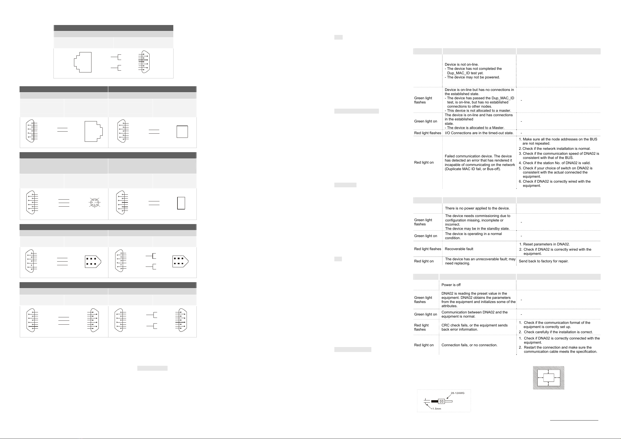
LED Indicators and Trouble-Shooting
There are 3 LED indicators on DNA02, Network Status LED, Module Status LED and Scan Port LED, for displaying
the connection status of the communication.
5.1 Network Status LED
LED status Indication How to deal with it?
Off
Device is not on-line.
- The device has not completed the
Dup_MAC_ID test yet.
- The device may not be powered.
1.Check the power of DNA02 and see if the
connection is normal.
2.Check if the node communication on the BUS is
normal.
3.Make sure at least 1 node is normally
communicating with the network through
DNA02.
Green light
flashes
Device is on-line but has no connections in
the established state.
- The device has passed the Dup_MAC_ID
test, is on-line, but has no established
connections to other nodes.
- This device is not allocated to a master.
-
Green light on
The device is on-line and has connections
in the established
state.
- The device is allocated to a Master.
-
Red light flashes
I/O Connections are in the timed-out state.
-
Red light on
Failed communication device. The device
has detected an error that has rendered it
incapable of communicating on the network
(Duplicate MAC ID fail, or Bus-off).
1. Make sure all the node addresses on the BUS
are not repeated.
2. Check if the network installation is normal.
3. Check if the communication speed of DNA02 is
consistent with that of the BUS.
4. Check if the station No. of DNA02 is valid.
5. Check if your choice of switch on DNA02 is
consistent with the actual connected the
equipment.
6. Check if DNA02 is correctly wired with the
equipment.
5.2 Module Status LED
LED status Indication How to deal with it?
Off There is no power applied to the device. Check the power of DNA02 and see if the
connection is normal.
Green light
flashes
The device needs commissioning due to
configuration missing, incomplete or
incorrect.
The device may be in the standby state.
-
Green light on The device is operating in a normal
condition. -
Red light flashes
Recoverable fault
1. Reset parameters in DNA02.
2. Check if DNA02 is correctly wired with the
equipment.
Red light on
The device has an unrecoverable fault; may
need replacing. Send back to factory for repair.
5.3 Scan Port Status LED
LED status
Indication How to deal with it?
Off Power is off Check the power of DNA02 and see if the
connection is normal.
Green light
flashes
DNA02 is reading the preset value in the
equipment. DNA02 obtains the parameters
from the equipment and initializes some of the
attributes.
-
Green light on
Communication between DNA02 and the
equipment is normal. -
Red light
flashes
CRC check fails, or the equipment sends
back error information.
1. Check if the communication format of the
equipment is correctly set up.
2. Check carefully if the installation is correct.
Red light on Connection fails, or no connection.
1. Check if DNA02 is correctly connected with the
equipment.
2. Restart the connection and make sure the
communication cable meets the specification.
t Installation & Wiring
Install DNA02 in an enclosure with sufficient space around it to
allow heat dissipation (see the figure).
DO NOT place the I/O signal wires and power supply wire in the
same wiring circuit.
DNA02
D
D
D
D
D>50mm
<1.5mm
28-12AWG
Use 28-12AWG (1.5mm) single or multiple core wire on I/O wiring terminals.
See the figure for its specification.
The terminal screws shall be tightened to 5.19 kg-cm (4.5 in-lbs).
Use 60°C /75°C copper wires only.
The content of this instruction sheet may be revised without prior notice. Please consult our distributors or
download the most updated version at http://www.delta.com.tw/industrialautomation

Other Delta Electronics Other manuals

Delta Electronics AE94BSTD User manual

Delta Electronics

Delta Electronics AE94BSTD User manual

Delta Electronics ENA01-MOD User manual

Delta Electronics

Delta Electronics ENA01-MOD User manual

Delta Electronics EXLNHJ1AE User manual

Delta Electronics

Delta Electronics EXLNHJ1AE User manual

Delta Electronics EXIO28RAE User manual

Delta Electronics

Delta Electronics EXIO28RAE User manual

Delta Electronics LA35L32F User manual

Delta Electronics

Delta Electronics LA35L32F User manual

Delta Electronics CG5 User manual

Delta Electronics

Delta Electronics CG5 User manual

Delta Electronics IFD8500 User manual

Delta Electronics

Delta Electronics IFD8500 User manual

Delta Electronics MA0505-SAOIN-A0 User manual

Delta Electronics

Delta Electronics MA0505-SAOIN-A0 User manual

Delta Electronics G3D User manual

Delta Electronics

Delta Electronics G3D User manual

Delta Electronics COA02 User manual

Delta Electronics

Delta Electronics COA02 User manual

Delta Electronics CG5 User manual

Delta Electronics

Delta Electronics CG5 User manual

Delta Electronics NovoConnect B360 User manual

Delta Electronics

Delta Electronics NovoConnect B360 User manual

Delta Electronics AS5 User manual

Delta Electronics

Delta Electronics AS5 User manual

Delta Electronics CG5B User manual

Delta Electronics

Delta Electronics CG5B User manual

Delta Electronics CG5 User manual

Delta Electronics

Delta Electronics CG5 User manual

Delta Electronics EXIO14RAE User manual

Delta Electronics

Delta Electronics EXIO14RAE User manual

Delta Electronics B07S200 User manual

Delta Electronics

Delta Electronics B07S200 User manual

Popular Other manuals by other brands

Timbertech RadianceRail installation manual

Timbertech

Timbertech RadianceRail installation manual

Visonic CLIP datasheet

Visonic

Visonic CLIP datasheet

SWAGBOARD Spectra Pro quick start guide

SWAGBOARD

SWAGBOARD Spectra Pro quick start guide

Panasonic EC-G02 instruction manual

Panasonic

Panasonic EC-G02 instruction manual

HYGIPLAS CE399 instruction manual

HYGIPLAS

HYGIPLAS CE399 instruction manual

Oksys ECOS-150 Use and instruction manual

Oksys

Oksys ECOS-150 Use and instruction manual

HID iCLASS SE R90 installation guide

HID

HID iCLASS SE R90 installation guide

HURST Mastershift 3-Speed Installation Kit installation instructions

HURST

HURST Mastershift 3-Speed Installation Kit installation instructions

GFB EX50 installation instructions

GFB

GFB EX50 installation instructions

Amos RF1B1AMUS user manual

Amos

Amos RF1B1AMUS user manual

CEMO Fuel Trolley 53l manual

CEMO

CEMO Fuel Trolley 53l manual

Spin PureZone Machine user manual

Spin

Spin PureZone Machine user manual

Cansec Invisible Reader installation instructions

Cansec

Cansec Invisible Reader installation instructions

unGer Stingray user manual

unGer

unGer Stingray user manual

Lindam MK0001-000 manual

Lindam

Lindam MK0001-000 manual

Adtec edje 4111 quick start guide

Adtec

Adtec edje 4111 quick start guide

HTC VIVE user guide

HTC

HTC VIVE user guide

BURG-WACHTER Universal Safe operating instructions

BURG-WACHTER

BURG-WACHTER Universal Safe operating instructions

manuals.online logo
manuals.online logoBrands
  • About & Mission
  • Contact us
  • Privacy Policy
  • Terms and Conditions

Copyright 2025 Manuals.Online. All Rights Reserved.