manuals.online logo
Brands
  1. Home
  2. •
  3. Brands
  4. •
  5. Delta Electronics
  6. •
  7. Other
  8. •
  9. Delta Electronics EXIO28RAE User manual

Delta Electronics EXIO28RAE User manual

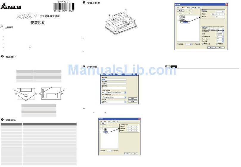
3請在使用之前,詳細閱讀本使用說明書。
3本擴充模組須搭配本公司 DOP-AE 系列人機產品進行使用,實施配線時,務必拔除/切斷人機電源。
3使用者使用本擴充模組時,必須將之安裝於具防塵、防潮及免於電擊/衝擊意外之外殼配線箱內。另必須具備
保護措施(如: 特殊之工具或鑰匙才可打開)防止非維護人員操作或意外衝擊本體,造成危險及損壞。
3交流輸入電源不可連接於輸入/出信號端,否則可能造成嚴重的損壞,因此請在上電之前再次確認電源配線。
3輸入電源切斷後,一分鐘之內,請勿觸摸內部電路。請勿在上電時觸摸任何端子。
3搭配使用的人機本體上之接地端子 務必正確的接地,可提高產品抗雜訊能力。
3擴充模組連接口之端子禁止外力重壓,避免導致產品損壞。
Xயݡᖎ
1.1 型號說明
DOP -EXIO 14 R AE
(1)(2)(3)(4)(5)
(1)產品名稱 DOP:Delta Operation Panel
(2)機種名稱 EXIO:Extension DIO
(3)點數 14:8 輸入點/6 輸出點
28:16 輸入點/12 輸出點
(4)輸出接點形式 R:繼電器
(5)適用機型 AE:DOP-AE 系列人機
1.2 產品外觀及各部介紹
1. 擴充模組連接口
2. 擴充模組螺絲固定孔
3. 輸出/入端子
4. 銘牌
1.3 機種型號
輸入/輸出規格
輸入單元 輸出單元
機種 電源 點數 形式 點數 形式
DOP-EXIO14RAE 8 6
繼電器
Relay
DOP-EXIO28RAE
5VDC
人機供應 16
直流 Sink 或
Source
12 繼電器
Relay
YΑఢ
項目規格備註
演算控制方式 內存程式.往返式來回掃描方式 -
輸入/輸出控制方式 結束再生方式(當執行至 END 指令) 僅主機的輸入/輸出有立即刷新指令
演算處理速度 基本指令 (30 us)應用指令(30 ~ 數百 us)
程式語言 指令 + 階梯圖 + SFC 含有步進指令
程式容量 999 Steps 具有內藏 EEPROM
指令種類基本順序指令 32 個(含步進階梯指令) 應用指令 59 種
步進繼電器
(停電保持用) 一般
步進點 128 點S10 ~ S127
一般用 1280 點M0 ~ M511,M768 ~ M999,744 點
M1000 ~ M1279,280 點*1
輔助
繼電器 停電
保持用 256 點M512 ~ M767
64 點T0~T63(100 ms 時基)
63 點T64~T126(10 ms 時基)
計時器 數位式
1 點T127(1 ms 時基)
一般用 112 點C0 ~ C111
停電
保持用 16 點C112 ~ C127
計數器
32bit 用13 點
C235,C236,C237,C238,C241,C242,
C244,C246,C247,C249,C251,C252,
C254(全部為停電保持)
一般用 408 點D0 ~ D407
資料
暫存器 停電
保持用 192 點D408 ~ D599
指標P 64 點P0 ~ P63
間接指定
暫存器 E/F2個E,F
10 進位 K16 位元:-32768 ~ +32767 32 位元:-2147483648 ~ +2147483647
定數16 進位 H16 位元:0000 ~ FFFF 32 位元:00000000 ~ FFFFFFFF
自我診斷/保護 輸出/入檢查、系統執行時間逾時檢查、不合法指令檢查、程式語法檢查及密碼
設定
監測/除 錯 程式執行時間顯示、位元/字元、元件設定
*1: M1001ăM1001ăM1002ăM1003ăM1020ăM1021ăM1022ăM1067ăM10068 ׶M1161 為特 M。
Z࿪ঈఢ
項目/機型 DOP-EXIO14RAE DOP-EXIO28RAE
電源電壓 5VDC,1A(人機提供)
消耗電力 0.25W 0.5W
雜訊免疫力
RS: Frequency: 80MHz ~ 1GHz, 1.4GHz ~ 2.0GHz, Test level 10V/m
CS: Frequency: 0.15MHz ~ 80MHz, Test level 10V (HMI power port & I/O line)
ESD: Air discharge ±8KV
EFT: ±1.5KV (HMI power port)
±1KV (I/O line)
Surge: ±2KV (HMI power port)
操作/儲存環境 操作:0℃~ 50℃(溫度),10 ~ 90%(濕度);
儲存:-40℃~ 85℃(溫度),10 ~ 90%(濕度)
耐振動/衝擊
IEC 61131-2 規定 不連續振動 5Hz-9Hz 3.5mm,9Hz-150Hz 1G
連續振動 5Hz-9Hz 1.75mm,9Hz-150Hz 0.5G
X, Y, Z 各方向 10 次
重量約95.5g 約116g
輸入點電氣規格
輸入形式 直流(SINK 或SOURCE)
輸入電壓 24VDC(5mA)
Off→On 16VDC 以上
動作位準 On→Off 14.4VDC 以下
反應時間 約10ms
輸出點電氣規格
輸出點形式 繼電器-R
電流規格 1.5A/1點(5A/COM)
電壓規格 250VAC,30VDC 以下
75VA(電感性)
最大負載 90 W(電阻性)
反應時間 約10 ms
機械壽命 2 × 10⁷次(無負載)
接點壽命 100,000 次(3A 250VAC/30VDC)
6,000 次(5A 250VAC/30VDC)
[щ྅ቢ
4.1 配線
22-16AWG
< 1.5m m
1. 輸出/入配線端請使用 28-16AWG(1.5mm
2
)單蕊祼線或多蕊線,剝線長度
6-7mm,端子規格如左所示。端子鏍絲扭力為 4.5Ib-in。
2. 在配線時請勿將輸入點信號線與輸出點或電源等動力線置於同一線槽內。
4.2 注意事項
使用環境
1. 請勿將擴充模組裝置於落塵大、油煙、金屬性粉塵及腐蝕性或可燃性氣體的環境當中。
2. 請勿將擴充模組裝置於高溫、結露之環境。
3. 請勿將擴充模組裝置有直接振動及衝擊的場所。
施工注意
1. 鎖鏍絲及配線時請避免微小的金屬導體掉入擴充模組內部。
2. 擴充模組與其它之控制元件應保持 50mm 以上之間隔,並應遠離高壓線及動力設備。
4.3 輸入點之配線
輸入點之入力信號為直流電源 DC 輸入,DC 型式共有兩種接法:SINK 及SOURCE,其定義如下:
Sink = 電流流入共用端 S/S Source = 電流流出共用端 S/S
S/S
X0
Sinking
S/S
X0
Sourcing
配線
直流形式
(DC Signal IN)輸入點回路等效電路 配線回路
SINK 模式
24VDC
0V
X0
S/S
+24V
SINK
+5V
OV S/S X0 X1 X2+24V
Sink Type
24VDC
直流形式
(DC Signal IN)輸入點回路等效電路 配線回路
SOURCE 模式
24VDC
0V
X0
S/S
+24V
SOURCE
+5V
0V S/S X0 X1 X2+24V
Source Type
24VDC
NOTE
1) 本說明書內所記載之規格若有變更,本公司恕不另行通知。當內容規格有所修正時,請洽詢代理商或至台達網站
http://www.delta.com.tw/industrialautomation/下載最新版本。
http://www.delta.com.tw/industri alautomation/
ᇴҜ IO ᕖ·ሀ௡
щ྅ᄲځ
ڦຍְี
1
2
3
4
3Please read this instruction carefully before use.
3DOP series Extension Digital I/O Module should be used with DOP-AE series HMI product. Ensure to
switch off the power before wiring.
3Please install this DOP series Extension Digital I/O Module in an enclosure free of airborne dust,
humidity, electric shock and vibration. The enclosure should prevent non-maintenance staff from
operating the device (e.g. key or specific tools are required for opening the enclosure) in case danger
and damage on the device may occur.
3DO NOT connect input AC power supply to any of the I/O terminals; otherwise serious damage may
occur. Check all the wiring again before switching on the power.
3DO NOT touch any internal circuit in 1 minute after the power is switched off. Do NOT touch any
terminal when the power is switched on.
3Make sure the ground terminal is correctly grounded in order to prevent electromagnetic
interference.
3DO NOT place any heavy objects on the connection port of DOP series Extension Digital I/O Module.
Doing so may damage the product.
XIntroduction
1.1 Model Explanation
DOP - EXIO 14 R AE
(1) (2) (3) (4) (5)
(1) Product Name DOP: Delta Operation Panel
(2) Series EXIO: Extension Digital I/O
(3) Input / Output Point 14: 8 input points / 6 output points
28: 16 input points / 12 output points
(4) Output Contact Type R: Relay
(5) Applicable HMI Series AE: DOP-AE Series HMI
1.2 Product Outline
1. Connection Port
2. Direct Mounting Hole
3. Input / Output Terminals
4. Nameplate
1.3 Model Name
Input / Output
Input Unit Output Unit
Model Name Power Point Type Point Type
DOP-EXIO14RAE 8 6 Relay
DOP-EXIO28RAE
5VDC,
supplied
by HMI 16
DC Type
Sink or
Source
12 Relay
YFunction Specifications
Item Specifications Remark
Control Method Stored program, cyclic scan system -
I/O Processing Method Batch I/O (refresh) Immediate refresh command available
only with I/O of the MPU
Execution Speed Basic command (30 us) Application command (30 ~ hundreds
us)
Program Language Commands + Ladder Diagram +
SFC Step commands included
Program Capacity 999 Steps Built-in EEPROM
Commands Basic commands: 32 (including the
STL commands) Application commands: 59
Step Relay
(Latched)
General
Step Point 128 Points S10 ~ S127
General 1280 Points M0 ~ M511, M768 ~ M999, 744 points;
M1000 ~ M1279, 280 points*1
Auxiliary
Relay Latched 256 Points M512 ~ M767
64 Points T0~T63 (100 ms time base)
63 Points T64~T126 (10 ms time base)
Timer Digital
1 Points T127 (1 ms time base)
General 112 Points C0 ~ C111
Latched 16 Points C112 ~ C127
Counter
32bit 13 Points
C235,C236,C237,C238,C241,C242,
C244,C246,C247,C249,C251,C252,
C254 (all of them are latched type)
General 408 Points D0 ~ D407
Data Register Latched 192 Points D408 ~ D599
Pointer P 64 Points P0 ~ P63
Index
Register E / F 2 E, F
Decimal K 16bit: -32768 ~ +32767 32bit: -2147483648 ~ +2147483647
Constant Hexadecim
al H 16bit: 0000 ~ FFFF 32bit: 00000000 ~ FFFFFFFF
Self Diagnosis / Protection I/O check, system execution timeout check, invalid command check, program
check and password settings
Monitor / Debug Program execution time display, bit / word, device settings
*1: M1000, M1001, M1002, M1003, M1020, M1021, M1022, M1067, M10068, and M1161 are the special auxiliary relays (special M).
ZElectrical Specifications
Item / Model Name DOP-EXIO14RAE DOP-EXIO28RAE
Power Supply Voltage 5VDC, 1A (supplied by HMI)
Power Consumption 0.25W 0.5W
Noise Immunity
RS: Frequency: 80MHz ~ 1GHz, 1.4GHz ~ 2.0GHz, Test level 10V/m
CS: Frequency: 0.15MHz ~ 80MHz, Test level 10V (HMI power port & I/O line)
ESD: Air discharge ±8KV
EFT: ±1.5KV (HMI power port)
±1KV (I/O line)
Surge: ±2KV (HMI power port)
Ambient Temperature /
Humidity
Operation: 0°C ~ 50°C (Temperature), 10 ~ 90% (Humidity),
Storage: -40°C ~ 85°C (Temperature), 10 ~ 90% (Humidity)
Vibration / Shock
IEC 61131-2 Compliant
5Hz≦f<9Hz = Continuous: 1.75mm / Occasional: 3.5mm
9Hz≦f≦150Hz = Continuous: 0.5g / Occasional: 1.0g
X, Y, Z directions for 10 times
Weight Approx. 95.5g Approx. 116g
Input Point Electric Specifications
Input Type DC (SINK or SOURCE)
Input Voltage 24VDC (5mA)
Off→On, above 16VDC
Active Level On→Off, below 14.4VDC
Response Time Approx. 10ms
Output Point Electric Specifications
Output Type Relay-R
Current Specifications 1.5A / 1 Point (5A/COM)
Voltage Specifications 250VAC, below 30VDC
75VA (Inductive)
Maximum Loading 90 W (Resistive)
Response Time Approx. 10 ms
Mechanical Life 2 × 10⁷times (without load)
Output Point Electric Specifications
Electrical Life 100,000 times (3A 250VAC/30VDC)
6,000 times (5A 250VAC/30VDC)
[Installation & Wiring
4.1 Wiring
22-16AWG
< 1.5m m
1. Please use the 28-16 AWG (1.5mm
2
) single-core bare wire (Solid type) or
the multi-core wire (Stranded type) for the I/O wiring. The stripped length of
the wire should be 6-7mm, and the torque specification of the screw for the
terminal is 4.5lb-in. Please refer to the specifications of the terminal shown
in the figure on the left.
2. DO NOT place the I/O signal wires and power supply wire in the same
wiring duct.
4.2 Caution
Environment
1. DO NOT install the Extension Digital I/O Module in a place subjected to corrosive or flammable gases,
liquids, or airborne dust or metallic particles.
2. DO NOT install the Extension Digital I/O Module in a location high temperature and high humidity (where
temperature and humidity will exceed specification).
3. DO NOT install the Extension Digital I/O Module in a location where vibration and shock will exceed
specification.
Wiring Note
1. Please avoid any conductive debris and tiny metal material enter the Extension Digital I/O Module when
screwing and wiring.
2. Allow a minimum space of 50mm between the Extension Digital I/O Module and other control devices, and
keep the Extension Digital I/O Module away from the high-voltage lines or any power equipment.
4.3 Input Point Wiring
There are two types of DC inputs, SINK and SOURCE, and they are defined as follows:
Sink = (common port for current input S/S) Source = (common port for current output S/S)
S/S
X0
Sinking
S/S
X0
Sourcing
Wiring
DC Signal IN Input point loop equivalent circuit Wiring loop
SINK mode
24VDC
0V
X0
S/S
+24V
SINK
+5V
OV S/S X0 X1 X2+24V
Sink Type
24VDC
DC Signal IN Input point loop equivalent circuit Wiring loop
SOURCE mode
24VDC
0V
X0
S/S
+24V
SOURCE
+5V
0V S/S X0 X1 X2+24V
Source Type
24VDC
NOTE
1) The content of this instruction sheet may be revised without prior notice. Please consult our distributors or download the most
updated version at http://www.delta.com.tw/industrialautomation.
http://www.delta.com.tw/industri alautomation/
Extension Digital I/O Module
Instruction Sheet
Warning
1
2
3
4
This manual suits for next models

1

Other Delta Electronics Other manuals

Delta Electronics AE94BSTD User manual

Delta Electronics

Delta Electronics AE94BSTD User manual

Delta Electronics IFD8500 User manual

Delta Electronics

Delta Electronics IFD8500 User manual

Delta Electronics CG5B User manual

Delta Electronics

Delta Electronics CG5B User manual

Delta Electronics DNA02 User manual

Delta Electronics

Delta Electronics DNA02 User manual

Delta Electronics CG5 User manual

Delta Electronics

Delta Electronics CG5 User manual

Delta Electronics EXIO14RAE User manual

Delta Electronics

Delta Electronics EXIO14RAE User manual

Delta Electronics G3D User manual

Delta Electronics

Delta Electronics G3D User manual

Delta Electronics NovoConnect B360 User manual

Delta Electronics

Delta Electronics NovoConnect B360 User manual

Delta Electronics EXLNHJ1AE User manual

Delta Electronics

Delta Electronics EXLNHJ1AE User manual

Delta Electronics ENA01-MOD User manual

Delta Electronics

Delta Electronics ENA01-MOD User manual

Delta Electronics MA0505-SAOIN-A0 User manual

Delta Electronics

Delta Electronics MA0505-SAOIN-A0 User manual

Delta Electronics COA02 User manual

Delta Electronics

Delta Electronics COA02 User manual

Delta Electronics CG5 User manual

Delta Electronics

Delta Electronics CG5 User manual

Delta Electronics B07S200 User manual

Delta Electronics

Delta Electronics B07S200 User manual

Delta Electronics CG5 User manual

Delta Electronics

Delta Electronics CG5 User manual

Delta Electronics LA35L32F User manual

Delta Electronics

Delta Electronics LA35L32F User manual

Delta Electronics AS5 User manual

Delta Electronics

Delta Electronics AS5 User manual

Popular Other manuals by other brands

Alees Rush 750 owner's manual

Alees

Alees Rush 750 owner's manual

LAMBORGHINI BVE 120 - SCHEMA manual

LAMBORGHINI

LAMBORGHINI BVE 120 - SCHEMA manual

Yale SHAW-BOX Operation & service manual

Yale

Yale SHAW-BOX Operation & service manual

Thetford C-402 installation manual

Thetford

Thetford C-402 installation manual

GOEBEL GO-39 instruction manual

GOEBEL

GOEBEL GO-39 instruction manual

IBM HS21 BLADECENTER - FOR SPECJBB2005 specification

IBM

IBM HS21 BLADECENTER - FOR SPECJBB2005 specification

Victron energy Cyrix-ct 12/24V-120A manual

Victron energy

Victron energy Cyrix-ct 12/24V-120A manual

berlinger Fridge-tag 2 Quick user guide

berlinger

berlinger Fridge-tag 2 Quick user guide

FSM TSRD operating instructions

FSM

FSM TSRD operating instructions

JVC HA-FX39BT instructions

JVC

JVC HA-FX39BT instructions

Blastrac 10DPS75 operating manual

Blastrac

Blastrac 10DPS75 operating manual

NEC NEC070417 Applications

NEC

NEC NEC070417 Applications

Trovan LID573 quick start guide

Trovan

Trovan LID573 quick start guide

Sunex Tools 66175FASJ owner's manual

Sunex Tools

Sunex Tools 66175FASJ owner's manual

Dennerle Osmosis ReMineral+ quick start guide

Dennerle

Dennerle Osmosis ReMineral+ quick start guide

SMART Board 3000i operating instructions

SMART Board

SMART Board 3000i operating instructions

Martin Audio W8LMD manual

Martin Audio

Martin Audio W8LMD manual

Smart+ Products SPP-PP1800-6WCH owner's manual

Smart+ Products

Smart+ Products SPP-PP1800-6WCH owner's manual

manuals.online logo
manuals.online logoBrands
  • About & Mission
  • Contact us
  • Privacy Policy
  • Terms and Conditions

Copyright 2025 Manuals.Online. All Rights Reserved.