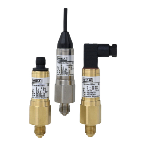
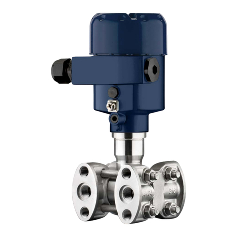
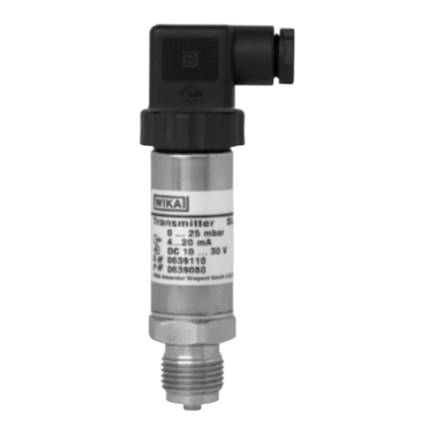
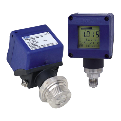
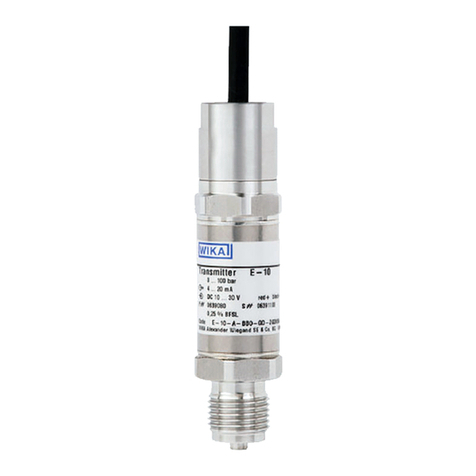
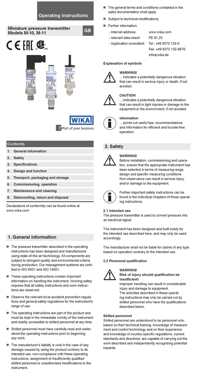
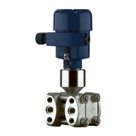
WIKA E-10 User manual

E-10, E-11
Operating instructions
Betriebsanleitung
Mode d'emploi
Manual de instrucciones
EN
DE
FR
ES
Druckmessumformer, Typen E-10 und E-11
Pressure transmitter, models E-10 and E-11
E-10 E-11
Transmisor de presión, modelos E-10 y E-11
Transmetteur de pression, types E-10 et E-11

2WIKA operating instructions pressure transmitter, models E-10 and E-11
11116552.11 EN/DE/FR/ES 03/2022
EN
DE
FR
ES
© 2016 WIKA Alexander Wiegand SE & Co. KG
All rights reserved. / Alle Rechte vorbehalten.
WIKA®is a registered trademark in various countries.
WIKA®ist eine geschützte Marke in verschiedenen Ländern.
Prior to starting any work, read the operating instructions!
Keep for later use!
Vor Beginn aller Arbeiten Betriebsanleitung lesen!
Zum späteren Gebrauch aufbewahren!
Lire le mode d‘emploi avant de commencer toute opération !
A conserver pour une utilisation ultérieure !
¡Leer el manual de instrucciones antes de comenzar cualquier trabajo!
¡Guardar el manual para una eventual consulta!
Betriebsanleitung, Typen E-10 und E-11 Seite 27 - 50
Operating instructions, models E-10 and E-11 Page 3 - 26
Mode d'emploi, types E-10 et E-11 Page 51 - 74
Manual de instrucciones, modelos E-10 y E-11 Pagina 75 - 98

11116552.11 EN/DE/FR/ES 03/2022
3WIKA operating instructions pressure transmitter, models E-10 and E-11
EN
Contents
Contents
1. General information 4
2. Design and function 5
3. Safety 6
Special conditions of use (X conditions) 10
4. Transport, packaging and storage 11
5. Commissioning, operation 12
6. Faults 18
7. Maintenance and cleaning 19
8. Dismounting, return and disposal 20
9. Specifications 22
Annex: EU declaration of conformity 51

11116552.11 EN/DE/FR/ES 03/2022
4WIKA operating instructions pressure transmitter, models E-10 and E-11
EN
1. General information
■
The instrument described in the operating instructions has been designed and manufactured using state-of-the-
art technology. All components are subject to stringent quality and environmental criteria during production. Our
management systems are certied to ISO 9001 and ISO 14001.
■
These operating instructions contain important information on handling the instrument.Working safely requires that
all safety instructions and work instructions are observed.
■
Observe the relevant local accident prevention regulations and general safety regulations for the instrument's range
of use.
■
The operating instructions are part of the product and must be kept in the immediate vicinity of the instrument and
readily accessible to skilled personnel at any time. Pass the operating instructions on to the next operator or owner
of the instrument.
■
Skilled personnel must have carefully read and understood the operating instructions prior to beginning any work.
■
The general terms and conditions contained in the sales documentation shall apply.
■
Subject to technical modications.
■
Further information:
- Internet address: www.wika.de / www.wika.com
- Relevant data sheet: PE 81.27
- Application consultant: Tel.: +49 9372 132-0
Fax: +49 9372 132-406

11116552.11 EN/DE/FR/ES 03/2022
5WIKA operating instructions pressure transmitter, models E-10 and E-11
EN
2. Design and function
2.1 Overview
Electrical connection with protective cap
Electrical connection without protective cap
Case, product label
Process connection, spanner ats
Process connection, thread (depending on version)
2.2 Description
Model E-10: Process connection with internal diaphragm (standard version)
Model E-11: Process connection with ush diaphragm for highly viscous or crystallising media that may clog the bore
of the process connection.
By means of a sensor element and by supplying power, the prevailing pressure in your application is converted into an
amplied standardised electrical signal via the deformation of a diaphragm. This electrical signal varies in proportion to
the pressure and can be evaluated accordingly.
2.3 Scope of delivery
■
Completely mounted pressure transmitter for ush design (model E-11) with pre-mounted sealings and plastic
protective cap
■
Operating instructions
Cross-check scope of delivery with delivery note.

11116552.11 EN/DE/FR/ES 03/2022
6WIKA operating instructions pressure transmitter, models E-10 and E-11
EN
3. Safety
3. Safety
3.1 Explanation of symbols
WARNING!
... indicates a potentially dangerous situation that can result in serious injury or death, if not avoided.
CAUTION!
... indicates a potentially dangerous situation that can result in light injuries or damage to property or the
environment, if not avoided.
DANGER!
... indicates a potentially dangerous situation in the hazardous area that can result in serious injury or
death, if not avoided.
WARNING!
... indicates a potentially dangerous situation that can result in burns, caused by hot surfaces or liquids,
if not avoided.
Information
... points out useful tips, recommendations and information for ecient and trouble-free operation.
3.2 Intended use
The pressure transmitter with ameproof enclosure is used for the continuous monitoring of gaseous media or
liquids in hazardous areas that require equipment with equipment protection level Gb.
For Ex marking, see chapter 3.7 “Ex marking”.
The instrument has been designed and built solely for the intended use described here, and may only be used
accordingly.
The manufacturer shall not be liable for claims of any type based on operation contrary to the intended use.

11116552.11 EN/DE/FR/ES 03/2022
7WIKA operating instructions pressure transmitter, models E-10 and E-11
EN
3.3 Improper use
WARNING!
Injuries through improper use
Improper use of the instrument can lead to hazardous situations and injuries.
▶
Refrain from unauthorised modifications to the instrument.
Any use beyond or dierent to the intended use is considered as improper use.
Do not use this instrument in safety or emergency shutdown devices.
3.4 Personnel qualification
WARNING!
Risk of injury should qualication be insucient!
Improper handling can result in considerable injury and damage to property.
▶
The activities described in these operating instructions may only be carried out by skilled personnel
who have the qualifications described below.
▶
Keep unqualified personnel away from hazardous areas.
Skilled personnel
Skilled personnel, authorised by the operator, are understood to be personnel who, based on their technical training,
knowledge of measurement and control technology and on their experience and knowledge of country-specic
regulations, current standards and directives, are capable of carrying out the work described and independently
recognising potential hazards.
Special operating conditions require further appropriate knowledge, e.g. of aggressive media.
3. Safety

11116552.11 EN/DE/FR/ES 03/2022
8WIKA operating instructions pressure transmitter, models E-10 and E-11
EN
3.5 Special hazards
DANGER!
Danger to life due to loss of explosion protection
Non-observance of these instructions and their contents may result in the loss of explosion protection.
▶
Observe the safety instructions in this chapter and further explosion protection instructions in these
operating instructions.
▶
Observe the information given in the applicable type examination certificate and the relevant country-
specific regulations for installation and use in hazardous areas (e.g. IEC 60079-14, NEC, CEC).
WARNING!
Physical injury and damage to property caused by hair-line cracks
The service life of the pressure transmitter is limited by a maximum number of load cycles.The maximum
number depends on the pressure prole of the application (extent of change in pressure, time of pressure
rise and pressure drop, ...). Once the maximum number of load cycles has been exceeded, it can lead to
leaks through hair-line cracks, which can cause physical injury and damage to property.
▶
Request the maximum number of load cycles from the manufacturer.
▶
Replace the pressure transmitter once it has exceeded the maximum number of load cycles.
▶
Take safety measures to eliminate hazards due to hair-line cracks.
WARNING!
Physical injuries and damage to property and the environment caused by hazardous media
Upon contact with hazardous media (e.g. oxygen, acetylene, ammable or toxic substances),
harmful media (e.g. corrosive, toxic, carcinogenic, radioactive), and also with refrigeration plants and
compressors, there is a danger of physical injuries and damage to property and the environment.
Should a failure occur, aggressive media with extremely high temperature and under high pressure or
vacuum may be present at the instrument.
▶
For these media, in addition to all standard regulations, the appropriate existing codes or regulations
must also be followed.
▶
Wear the requisite protective equipment.
3. Safety

11116552.11 EN/DE/FR/ES 03/2022
9WIKA operating instructions pressure transmitter, models E-10 and E-11
EN
WARNING!
Physical injuries and damage to property and the environment through residual media
Residual media in the dismounted instrument can result in a risk to persons, the environment and equipment.
▶
Take sufficient precautionary measures.
▶
Do not use this instrument in safety or emergency shutdown devices.
Further important safety instructions can be found in the individual chapters of these operating
instructions.
3.6 Labelling, safety marks
Product label (example)
Model designation
Measuring range
Output signal
Supply voltage
P# article number and S# serial number
Additional text (optional)
Model code
Coded date of manufacture
Approval-related data (→ see chapter 3.7 “Marcaje Ex” and 3.8 “Condiciones especiales para la utilización (X-Conditions)”)
Further approvals
Pin assignment
11
3. Safety
Made in GermanyWIKA Alexander Wiegand SE & Co. KG DE - 63911 Klingenberg
0158
11

11116552.11 EN/DE/FR/ES 03/2022
10 WIKA operating instructions pressure transmitter, models E-10 and E-11
EN
Before mounting and commissioning the instrument, ensure you read the operating instructions!
3.7 Ex marking
ATEX and IECEx approval
The pressure transmitter is approved for use in gas hazardous areas, zone 1 and zone 2 and certied in accordance
with the following standards:
IECEx ATEX
Number of the certicate IECEx DEK 15.0048X KEMA 05 ATEX 2240
Applied standards IEC 60079-0
IEC 60079-1
EN IEC 60079-0
EN 60079-1
Marking of equipment 1) Ex db IIC T6 … T1 Gb II 2G Ex db IIC T6 … T1 Gb
1) For temperature specications, see chapter 3.8 “Conditions spéciques d'utilisation (conditions X)”
3.8 Special conditions of use (X conditions)
Ambient and medium temperature range:
-40 ... +102 °C [-40 ... +215 °F] for E-1*-*-***-**-**DX**-**
-40 ... +105 °C [-40 ... +221 °F] for E-1*-*-***-**-**CX**-**
The correlation between the maximum ambient and medium temperature and the temperature class is shown in the
table below:
3. Safety

11116552.11 EN/DE/FR/ES 03/2022
11WIKA operating instructions pressure transmitter, models E-10 and E-11
EN
Max. temperature ranges 1) 2) E-10-*-***-**-**CX**-**
E-11-*-***-**-***CX**-**
E-10-*-***-**-**DX**-**
E-11-*-***-**-***DX**-**
Max. ambient temperature range Tamb T1 ...T4 -40 … +105 °C [-40 ... +221 °F] T1 ...T4 -40 ... +102 °C [-40 ... +215 °F]
T5 -40 ... +75 °C [-40 ... +167 °F] T5 -40 ... +75 °C [-40 ... +167 °F]
T6 -40 … +60 °C [-40 ... +140 °F] T6 -40 … +60 °C [-40 ... +140 °F]
Max. medium temperature range Tmedium T1 ... T4 -40 … +105 °C [-40 ... +221 °F] T1 ...T4 -40 … +105 °C [-40 ...+221 °F] 3)
T5 -40 ... +75 °C [-40 ... +167 °F] T5 -40 ... +75 °C [-40 ... +167 °F]
T6 -40 … +60 °C [-40 ... +140 °F] T6 -40 … +60 °C [-40 ... +140 °F]
1) -40 °C [-40 °F] only valid when no sealing is used.
Sealings from NBR only admissible from -30 °C [-22 °F] ... +100 °C [+212 °F].
Sealings from FPM/FKM only admissible from -15 °C [5 °F] ... +102 °C / 105 °C [215 °F / 221 °F].
2) For IP code IP67 the ambient temperature range is limited to -40 °C ... +80 °C [-40 ... +176 °F].
3) A maximum medium temperature of 102 °C [215 °F] or 105 °C [221 °F] for T4 … T1 is permitted if the pressure transmitter is installed in such a way that its
temperature above the hexagon of the process connection does not exceed 102 °C [215 °F] or 105 °C [221 °F].
4. Transport, packaging and storage
4.1 Transport
Check the pressure transmitter for any damage that may have been caused during transportation.
Obvious damage must be reported immediately.
Fit the protective cap before transporting the instrument in order to protect the process connection from damage.
4.2 Packaging and storage
Do not remove packaging until just before mounting.
Keep the packaging as it will provide optimum protection during transport (e.g. change in installation site, sending for
repair).
Fit the protective cap before storing the instrument in order to protect the process connection from damage (for
model E-11).
3. Safety / 4.Transport, packaging and storage

11116552.11 EN/DE/FR/ES 03/2022
12 WIKA operating instructions pressure transmitter, models E-10 and E-11
EN
Avoid exposure to the following factors:
■
Direct sunlight or proximity to hot objects
■
Mechanical vibration, mechanical shock (putting it down hard)
■
Soot, vapour, dust and corrosive gases
■
Hazardous environments, ammable atmospheres
Store the instrument in its original packaging in a location that fulls the conditions listed above. If the original
packaging is not available, pack and store the instrument as described below:
1. Wrap the instrument in an antistatic plastic lm.
2. Place the instrument, along with shock-absorbent material, in the packaging.
3. If stored for a prolonged period of time (more than 30 days), place a bag containing a desiccant inside the packaging.
5. Commissioning, operation
5.1 Checking the instrument
Only use the pressure transmitter if it is in perfect condition with respect to safety.
Prior to commissioning, the pressure transmitter must be subjected to a visual inspection.
■
Leaking uid is indicative of damage.
Diaphragm inspection (for model E-11)
Inspect the diaphragm before starting to use the pressure transmitter as this part is essential for safety.
4. Transport, packaging and storage / 5. Commissioning, operation

11116552.11 EN/DE/FR/ES 03/2022
13WIKA operating instructions pressure transmitter, models E-10 and E-11
EN
5.2 Mechanical mounting
Electrical connection hexagon: Only use it to secure the transmitter when mounting it on the electrical conduit or as a counterholder when
removing the metal protective cap (spanner width 27).
Process connection hexagon: Use it to install the transmitter process connection (spanner width 27) Max. 50 Nm [36.9 foot-pounds]
Drainage opening
Spanner ats of the metal protective cap: Only use them to remove the metal protective cap when using an electrical conduit
(spanner width 24).
Metal protective cap
Plastic protective cap
Requirements for the mounting point
The mounting point must meet the following conditions:
■
Sealing faces are clean and undamaged.
■
Sucient space for a safe electrical installation.
■
For information on tapped holes and welding sockets, see Technical information IN 00.14 at www.wika.com.
■
Permissible ambient and medium temperatures remain within the performance limits. Consider possible restrictions
on the ambient temperature range caused by mating connector used.
→ For performance limits, see chapter 9 “Datos técnicos”
■
With ush process connections (model E-11), remove the protective cap not until shortly before mounting.
During installation, ensure that the diaphragm is not damaged.
■
With model E-10, a sealing must be tted to the process connection. Exceptions are instruments with self-sealing
thread (e.g. NPT thread). For model E-11, the sealing ring is included in the delivery.
For further information on sealings, see WIKA data sheet AC 09.08
5. Commissioning, operation

11116552.11 EN/DE/FR/ES 03/2022
14 WIKA operating instructions pressure transmitter, models E-10 and E-11
EN
Sealing variants
Mounting the instrument
The max. torque depends on the mounting point (e.g. material and shape). If you have any questions,
please contact our application consultant.
→ For contact details, see chapter 1 “General information” or the back page of the operating instructions.
1. Seal the sealing face (→ see “Sealing variants”).
2
.
At the mounting point, screw the pressure transmitter in hand-tight.
3
.
Tighten the process connection hexagon with a torque spanner using the spanner ats.
Max. torque: 50 Nm [36.9 foot-pound]
Please observe that the threads are not skewed.
Parallel threads
Seal the sealing face with flat gasket, lens-type
sealing ring or WIKA profile sealing.
per EN 837 per ISO 1179-2 (formerly
DIN 3852-E)
Tapered threads
Wrap threads with sealing material
(e.g. PTFE tape).
NPT, R and PT
5. Commissioning, operation

11116552.11 EN/DE/FR/ES 03/2022
15WIKA operating instructions pressure transmitter, models E-10 and E-11
EN
WARNING
Danger to life due to loss of explosion protection from damaged process connection
The diaphragm of the ush process connection is a safety-relevant component. If it is damaged, the
explosion protection is no longer guaranteed.Through any explosion resulting from this, there will be a
high danger to life.
▶
Before commissioning the pressure transmitter, the diaphragm of the ush process connection
should be checked for visible damage.
▶
Leaking uid is indicative of a damaged diaphragm.
▶
Protect the diaphragm from contact with abrasive media and against any impacts.
▶
Observe the specications for the use of the pressure measuring instrument in combination with
aggressive/corrosive media and for avoiding mechanical hazards.
▶
Only use the pressure transmitter if it is in perfect condition with respect to safety.
WARNING
Danger to life through improper mounting
Improper installation can lead to the loss of the explosion protection and to life-threatening situations.
▶
Adhere to the permissible ambient and medium temperatures which are valid for this area on
the basis of the specied temperature classes. (→ see chapter 3.8 “Special conditions of use
(X conditions)” and chapter 9 “Datos técnicos”).
5. Commissioning, operation

11116552.11 EN/DE/FR/ES 03/2022
16 WIKA operating instructions pressure transmitter, models E-10 and E-11
EN
5.3 Electrical mounting
WARNING!
Danger to life through improper mounting
If the pressure transmitter is not mounted properly, the explosion protection can no longer be ensured.
▶
Do not remove the cable connection.
▶
Use the electrical connection as originally supplied. It must not be bypassed or changed (except for
the cable length).
▶
Fine-stranded leads with bare ends must be finished with end splices (cable preparation)
■
Use and assemble connection cable that is suitable for the application.
■
Clamp the free cable end to a suitable certied clamp box or outside the hazardous area.
■
Use the pressure transmitter with shielded cable and ground the shield on at least one end of the lead, if the lines
are longer than 30 m or leave the building.
■
Ground the case via the process connection to protect the pressure transmitter against electromagnetic elds and
electrostatic discharge.Include the case in the equipotential bonding of the application.
For instruments with cable outlet, the shield is connected to the case.The simultaneous connection of the case and the
cable shield to ground is only permitted if any potential losses between the shield connection (e.g. at the power supply)
and the case can be excluded (see EN 60079-14).
Additional information for version E-1*-*-***-**-**DX**-** with protective cap
For installation with electrical conduit, the metal protective cap can be removed.
For installation without electrical conduit, the metal protective cap must not be removed.
Requirements for electrical connection
■
Ingress protection IP67 in accordance with IEC 60529 (protect drainage openings of the metal protective cap from
dirt to prevent water accumulation).
■
For cable outlets, make sure that no moisture enters at the cable end.
5. Commissioning, operation

11116552.11 EN/DE/FR/ES 03/2022
17WIKA operating instructions pressure transmitter, models E-10 and E-11
EN
Requirement for shield and grounding
The pressure transmitter must be grounded via the process connection.
When working during a running process operation, measures to prevent electrostatic discharge on the connection
terminals should be taken, as a discharge could lead to temporary corruption of the measured value.
Cable outlet with 2 m length
3-wire2-wire
red
red
black
black
brown
Shield
(connected to case)
Shield
(connected to case)
Legend:
Voltage supply
Load
UB+/Sig+ Positive supply / output terminal
0V/Sig- Negative supply / output terminal
5.4 Functional check
The output signal must be proportional to the prevailing pressure. If this is not the case, this may indicate a damaged
diaphragm of the process connection. In this case, see chapter 6 “Errores”.
5. Commissioning, operation

11116552.11 EN/DE/FR/ES 03/2022
18 WIKA operating instructions pressure transmitter, models E-10 and E-11
EN
6. Faults
CAUTION!
Physical injuries and damage to property and the environment
If faults cannot be eliminated by means of the listed measures, the pressure transmitter must be taken
out of operation immediately.
▶
Ensure that pressure or signal is no longer present and protect against accidental commissioning.
▶
Contact the manufacturer.
▶
If a return is needed, please follow the instructions given in chapter 8.2 “Return”.
WARNING!
Physical injuries and damage to property and the environment caused by hazardous media
Upon contact with hazardous media (e.g. oxygen) and also with refrigeration plants and compressors,
there is a danger of physical injuries and damage to property and the environment.
▶
Should a failure occur, media with extremely high temperature and under high pressure or vacuum
may be present at the instrument.
▶
For these media, in addition to all standard regulations, the appropriate existing codes or regulations
must also be followed.
▶
Wear the requisite protective equipment.
In the event of any faults, rst check whether the pressure transmitter is mounted correctly, mechanically and
electrically.
If complaint is unjustied, the handling costs will be charged.
Fault Possible cause Measure
No output signal No/wrong supply voltage or current pulse Correct the supply voltage according
to the operating instructions 1)
Cable break Check the continuity
No/wrong output signal Wiring error (e.g. 2-wire wired as 3-wire) Observe the pin assignment (see
product label / operating instructions)
Constant output signal upon
change in pressure
Mechanical overload caused by overpressure Replace instrument; if it fails
repeatedly, contact the manufacturer 1)
Constant output signal upon
change in pressure
Wrong supply voltage or current pulse Replace instrument
6. Faults

11116552.11 EN/DE/FR/ES 03/2022
19WIKA operating instructions pressure transmitter, models E-10 and E-11
EN
Fault Possible cause Measure
Signal span drops/too small Diaphragm damaged, e.g. due to impacts, abrasive/
aggressive medium; corrosion at diaphragm/process
connection; transmission medium missing
Contact manufacturer and replace
instrument
Signal span too small Supply voltage too high/low Correct the supply voltage according
to the operating instructions
Mechanical overload caused by overpressure Replace instrument
Signal span drops Moisture has entered (e.g. at the cable end) Fit the cable correctly
Signal span varies EMC interference sources in the environment, e.g.,
frequency converter
Shield instrument; cable shield;
remove source of interference
Instrument not grounded Ground the instrument
Strongly uctuating supply voltage Stabilise supply voltage, suppress
interference
Strongly uctuating pressure of the process medium Dampening; consulting by the
manufacturer
1) After the adjustment, check that the system is functioning correctly. If the error persists, send the instrument for repair (or replace the instrument). If the problem
persists, contact our sales representative.
7. Maintenance and cleaning
7.1 Maintenance
This pressure transmitter is maintenance-free.
Repairs must only be carried out by the manufacturer.
7.2 Cleaning
CAUTION!
Unsuitable cleaning agents
Cleaning with unsuitable cleaning agents may damage the instrument and the product label.
▶
Do not use any aggressive cleaning agents.
▶
Do not use any hard or pointed objects.
▶
Do not use any abrasive cloths or sponges.
6. Faults / 7. Maintenance and cleaning

11116552.11 EN/DE/FR/ES 03/2022
20 WIKA operating instructions pressure transmitter, models E-10 and E-11
EN
1. Depressurise and de-energise the pressure transmitter.
2. Wipe the instrument surface using a soft, damp cloth. Electrical connections must not come into contact with
moisture!
8. Dismounting, return and disposal
8.1 Dismounting
WARNING!
Physical injuries and damage to property and the environment caused by hazardous media
Upon contact with hazardous media (e.g. oxygen, acetylene, ammable or toxic substances),
harmful media (e.g. corrosive, toxic, carcinogenic, radioactive), and also with refrigeration plants and
compressors, there is a danger of physical injuries and damage to property and the environment.
▶
Should a failure occur, aggressive media with extremely high temperature and under high pressure
or vacuum may be present at the instrument.
▶
Wear the requisite protective equipment.
WARNING!
Risk of burns!
During dismounting there is a risk of dangerously hot media escaping.
▶
Let the instrument cool down sufficiently before dismounting it!
Dismounting the instrument
1. Depressurise and de-energise the pressure transmitter.
2
.
Disconnect the electrical connection.
3
.
Unscrew the pressure transmitter with a spanner using the spanner ats.
8.2 Return
Strictly observe the following when shipping the instrument:
All instruments delivered to WIKA must be free from any kind of hazardous substances (acids, bases, solutions, etc.)
and must therefore be cleaned before being returned.
7. Maintenance and cleaning / 8. Dismounting, return and disposal
Other manuals for E-10
3
This manual suits for next models
1
Table of contents
Languages:
Other WIKA Transmitter manuals
Popular Transmitter manuals by other brands

HumanTechnik
HumanTechnik lisa combi II RF operating instructions

Emerson
Emerson Rosemount 3144P Reference manual

SVS
SVS SHT-7 Series operating instructions

Dwyer Instruments
Dwyer Instruments 685 Series Installation and operating instructions

Moore Industries
Moore Industries SPA2 TPRG manual

Questtel
Questtel L-1SDI-FE-3G-MN-TX user manual