Delta-q IC650 User manual

IC650 Troubleshooting Guide
Delta-Q
IC
650
650W Industrial BatteryCharger
Delta-Q Technologies Corp.
3755 Willingdon Avenue
Burnaby, BC V5G 3H3
CANADA
Web: www.delta-q.com
Phone: +1.604.337.1110
E-mail: suppor[email protected]
© 2015 Delta-Q Technologies Corp. All rights reserved.
Date: 22/04/2015

Delta-Q IC650 Troubleshooting Guide: Table of Contents
1.0 Charger Interface 4
2.0 IC650 Conguration 6
3.0 Charger Fault Codes 8
4.0 Charger Error Codes 9

4
1.0 Charger Interface
Solid red = Charger fault
See display panel for details
Flashing amber = External error condition - caution
See display panel for details
Flashing green = USB port active
Solid green = Safe to remove USB flash drive
Flashing green = Low state of charge
Solid green = High state of charge
Flashing green = High state of charge
Solid green = Charge completed
Solid blue = AC power available
1. The Charging Output Indicator is solid yellow when the charger output is active. Take appropriate
actions while handling the charger, as there is a risk of electric shock.
2. The USB Host Port provides read and write USB functionality. Using a standard USB flash drive, a
user can download charge tracking data, and update the charger’s software and charging profiles.
See the USB Host Port, IC650 Configuration, and Charge Cycle Tracking Data sections for more
information.
3. The Charge Profile / Error Display shows one of four possible codes to indicate different conditions:
‘F’ codes mean that an internal fault condition has caused charging to stop.
‘E’ codes mean that an external error condition has caused charging to stop.
‘P’ codes mean that the charger programming mode is active.
‘USB’ code meaning that the USB interface is active, and the USB flash drive should not be
removed.
The ‘E,’‘F’ and ‘P’ codes are followed by three numbers and a period to indicate different conditions
(e.g. E-0-0-4.). See the Charger Fault Codes or Charger Error Codes sections for details on these
conditions and their solutions. ‘P’ codes indicate the charging profile number.
4. The Select Charge Profile Button is used to select a charge profile from those stored on the
charger. Up to 25 charge profiles can be stored. See the Selecting A Charge Profile section for
instructions.
Fault / Error / USB Indicator
Battery Charging Indicator
AC Power Indicator
USB Host Port
Charging Output Indicator1
Charge Prole / Error Display2
Select Charge Prole Button3
Status Bar Display Panel

5
1.1 Normal Operation: Bulk charging, <80% complete
1.2 Absorption / Finish phase, >80% complete
1.3 Charging complete

6
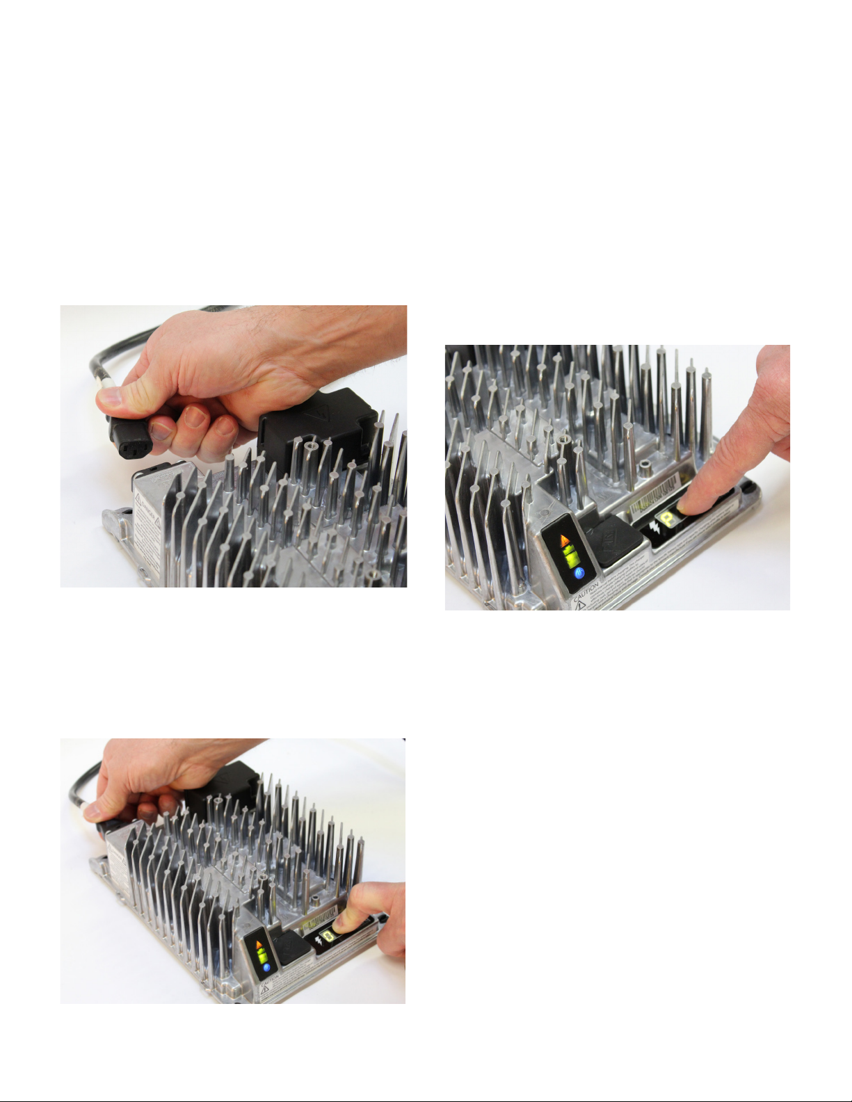
1. Disconnect AC input from the charger, or from the
wall outlet. Wait 30 seconds for the input relay to
open.
2. While reconnecting AC input, press and hold the
Select Charge Prole Button. Hold the button
(approximately 10 seconds) through the light
check function until Error Indicator is on (in
amber) and Battery Charging Indicator (in green)
starts ashing.
3. Press and release the Select Charge Prole Button
to advance through charging proles loaded on
the charger. The selected charging prole will
be displayed up to three times (e.g.“P-0-1-1”for
Prole 11).*
*Process will time out and prole will remain
unchanged if there is 15 seconds of inactivity, a
prole number is allowed to display three times, or if
AC power is cycled.
4. Once the desired charging prole is displayed,
press and hold the Select Charge Prole button
for 10 seconds to conrm selection and exit
Prole Selection Mode. When the charge prole
is conrmed, the Error Indicator and Battery
Charging INdicator lights will turn o, while the
blue AC Power Indicator remains lit. At this point,
the button can be released.
5. Press the Select Charge Prole Button to check
that the desired prole is selected.
2.0 IC650 Conguration
There are two ways to alter the conguration on the IC650 Charger:
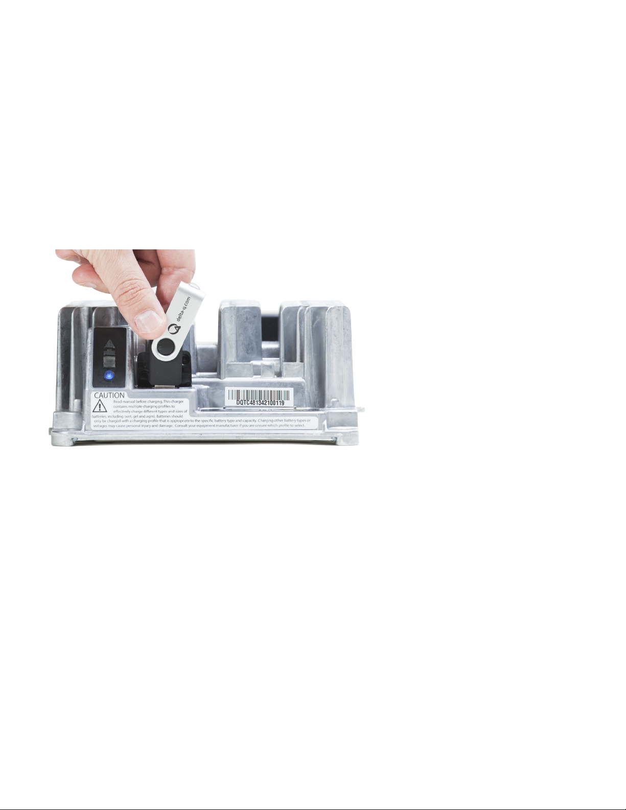
1. Use the Select Charge Prole Button.
2. Use a pre-programmed USB ash drive.
Figure 1.Disconnect AC input from the charger.
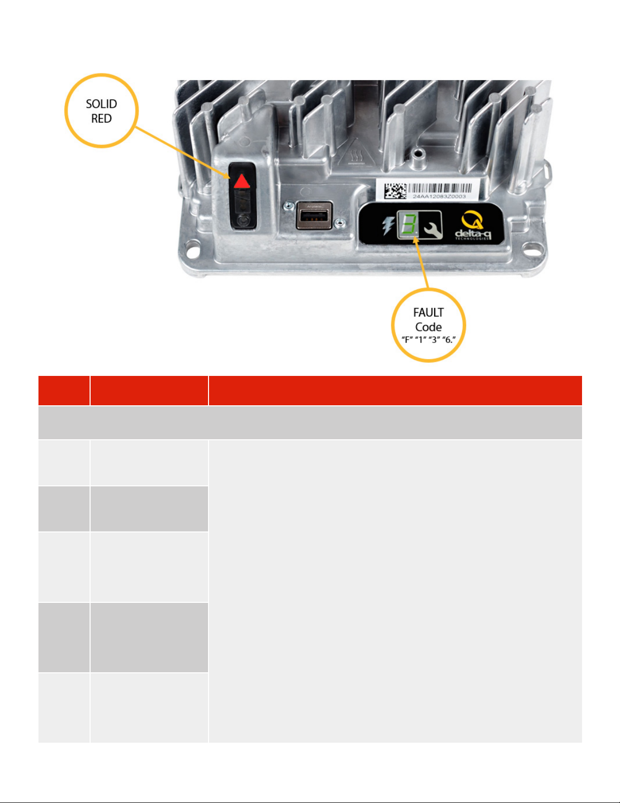
2.1 Selecting A Charge Prole Using the ‘Select Charge Prole Button’
Figure 2. Reconnect AC input while holding the
Select Charge Prole Button.
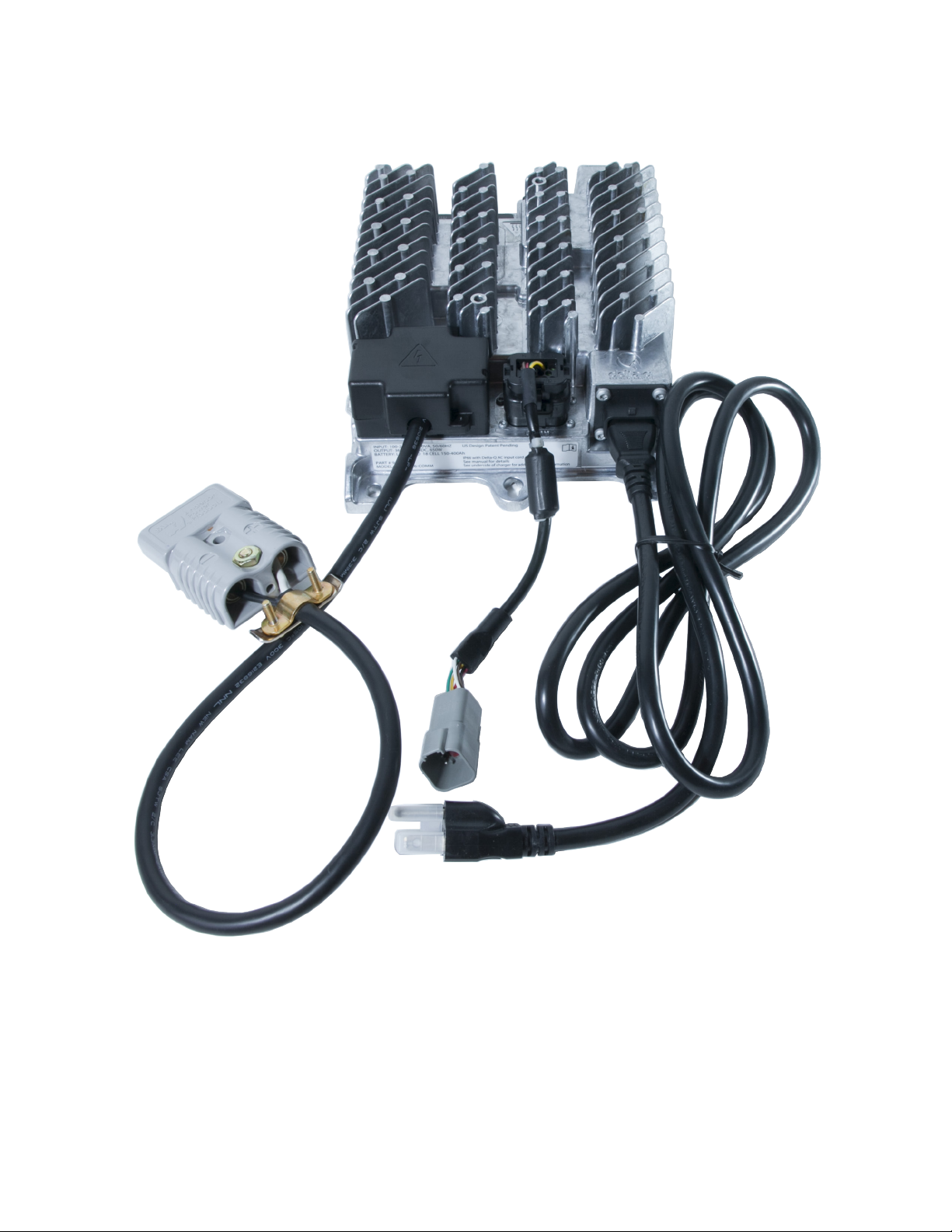
Figure 3. Press the Select Charge Prole Button
to advance through the charge proles. When the
desired charge prole appears, hold the button for 10
seconds to conrm your selection.

7
2.2 Conguring the IC650 Charger Using a USB Flash Drive
Using the Delta-Q software, USB storage drives can be pre-programmed to certain charger congurations.
To use the USB port, follow these steps:
1. Insert the USB ash drive at any time, but preferably not during a charge cycle. Stop the charge cycle by
removing AC power or the DC connection to the batteries. The charger can power the USB port from the
AC connection (DC disconnected) or from the DC connection (AC disconnected).
2. If there is enough disk space (about 2 mb), the charger will write charge tracking data to the drive. The
Fault / Error / USB Indicator will ash green during reading and writing.
3. If the drive contains compatible conguration les, the charger will load them.
4. The IC650 Charger will briey reset.
5. Remove the drive when the Fault / Error / USB indicator is solid green.
Figure 4.Insert the USB ash drive to begin the reprogramming process.
When complete, the Fault / Error / USB indicator will be solid green as shown.

8
3.0 Charger Fault Codes
Fault
Code Description Troubleshooting / Customer Actions
If a unit is not functioning and an Error is not indicated or logged, and this condition persists after cycling both AC and DC, it
should be sent back to Delta-Q for root cause analysis.
F-0-0-1 PFC failure - PFC
Excessive Leakage
Fault
Internal charger fault. Remove AC and battery for minimum 30 seconds and retry
charger. If fault persists, contact the manufacturer of your vehicle/machine or
Delta-Q Technologies.
F-0-0-2 PFC failure - PFC
Excessive Leakage
Fault
F-0-0-3 PFC has taken too long
to boost
F-0-0-4 The charger has been
unable to calibrate the
current offset
F-0-0-5 The output relay
voltage is too high
when relay is closed

9
4.0 Charger Error Codes
Battery and Set Up Errors
Error
Code Description Troubleshooting / Customer Actions
E-0-0-1
E-0-2-1
High battery voltage
error
Battery Voltage is too high to charge. Check the battery voltage and cable
connections. Check battery size and condition (could be too full to charge). This
error will automatically clear once the condition has been corrected.
E-0-0-2
E-0-2-2
Low battery voltage Battery Voltage is too low to charge. Check the battery voltage and cable
connections. Check battery size and condition. This error will automatically clear
once the condition has been corrected.
E-0-0-3 Charge timeout Charge Timeout caused by battery pack not reaching required voltage within safe
time limit. Possible causes: Poor battery health. Very deeply discharged battery.
Poorly connected battery. Extra loads. Replace battery pack. Check DC connections.
Charger output reduced due to high temperatures. This error will automatically clear
once the charger is reset by cycling DC.
E-0-0-4 Battery defective Battery could not be trickle charged up to the minimum voltage. Battery voltage
has not reached the level for normal charge cycle to take place, Check for shorted
or damaged cells. Replace battery pack. Check DC connections. This error will
automatically clear once the charger is reset by cycling DC.
E-0-0-7 Ah limit rxceeded Safety limit exceeded. Possible causes: Poor battery health. Very deeply discharged
battery. Poorly connected battery. High parasitic loads on battery while charging.
Possible solutions: Replace battery pack. Check DC connections. Disconnect parasitic
loads. This error will automatically clear once the charger is reset by cycling DC.
E-0-0-8 Battery temperature out
of range error
Check temperature sensor and connections. Reset charger. This error will
automatically clear once the condition has been corrected.

10
Error
Code Description Troubleshooting / Customer Actions
E-0-1-2 Reverse polarity error Battery is connected the wrong way around. Check the battery connections. This
error will automatically clear once the condition has been corrected.
E-0-1-3 Battery does not take
current
Battery voltage is detected but the charger is unable to charge the battery. This can
be due to an electrical device connected between the charger and the battery, which
passes through voltage but not current verify correct set up with OEM.
E-0-2-3
E-0-2-5
AC voltage out of range AC voltage is out of range. Connect charger to an AC source that provides stable
AC between 85 - 270 VAC / 45-65 Hz. This error will automatically clear once the
condition has been corrected.
Software / Algorithm Error - Quote error code to OEM support to assist with
troubleshooting
Error
Code Description Troubleshooting / Customer Actions
E-0-1-1
E-0-2-9
E-0-3-0
E-0-3-2
E-0-3-8
Charger is disabled by
External command e.g.
CANbus
Charger has been disabled by an external controller over the CANbus network
contact OEM for instruction.
E-0-1-6
E-0-1-8
E-0-1-9
E-0-2-6
Software error The software update failed. Ensure the USB Flash Drive is properly formatted and
retry the update by reinserting the USB Flash Drive into the charger. If software
updates continue to fail, contact Delta-Q.
E-0-2-0
E-0-2-8
Algorithm error The selected charging prole is incompatible with the charger software. Update
charger software or select a dierent charging prole. Ensure default algorithm is
selected.
E-0-1-7
E-0-2-7
USB error There has been a problem mounting or un mounting the USB Flash Drive. Remove
and re-insert the USB Drive. If the condition persists then remove AC and battery for
minimum 30 seconds and retry charger. If the problem persists then contact Delta-Q
for further help.
Configuration Error - Quote error code to OEM support to assist with troubleshooting
Error
Code Description Troubleshooting / Customer Actions
E-0-1-4
E-0-1-5
E-0-2-4
E-0-3-1
E-0-3-3
E-0-3-4
E-0-3-5
E-0-3-6
E-0-3-7
Congurations error There is an error with the charger’s internal conguration, Contact the OEM or
Delta-Q and quote the error code. USB drive update may be provided to clear error.

11
Delta-Q IC650
650W Industrial BatteryCharger
www.delta-q.com
Other manuals for IC650
1
Other Delta-q Batteries Charger manuals

Delta-q
Delta-q QuiQ User manual

Delta-q
Delta-q EXIDE ACH027M24101 User manual

Delta-q
Delta-q RC Series User manual

Delta-q
Delta-q QuiQ 912-24 series User manual

Delta-q
Delta-q IC650 User manual

Delta-q
Delta-q QUIQ Series User manual

Delta-q
Delta-q QuiQ-dci User manual

Delta-q
Delta-q RQ Series User manual

Delta-q
Delta-q QuiQ 912-24xx User manual

Delta-q
Delta-q IC SERIES User manual
Popular Batteries Charger manuals by other brands

GYS
GYS NEOSTART 320 Translation of the original instructions

eMotorWerks
eMotorWerks Juicebox Pro 32 manual

HEINE OPTOTECHNIK
HEINE OPTOTECHNIK NT300 manual

Christie
Christie C2536D Installation and operating instructions

Poly
Poly ROVE setup sheet

ULTIMATE SPEED
ULTIMATE SPEED USWB 11 A2 Operation and safety notes