Kohler GM88594-KP1-QS User manual

Mobile Generator Sets
Model:
Paralleling Box
GM88594-KP1-QS
Applicable Generator Set Models:
30--175 kW Mobile Generator Sets
equipped with the Decision-Makerr3500 Controller
TT-1672 10/16a
Installation


Table of Contents
TT-1672 10/16 Table of Contents 3
Safety Precautions and Instructions 5.........................................................
Introduction 7...............................................................................
List of Related Materials 7......................................................
Service Assistance 8.........................................................................
Section 1 Specifications and Features 9......................................................
1.1 Introduction 9...........................................................
1.1.1 Generator Management Mode 9...................................
1.1.2 Redundant Mode 9..............................................
1.1.3 Load Management 9.............................................
1.2 Paralleling Box Features 9................................................
1.3 Requirements 10.........................................................
1.4 Specifications 10.........................................................
1.5 System Installation Overview and Interconnection Diagram 10..................
Section 2 Transportation and Location 13......................................................
2.1 Introduction 13...........................................................
2.2 Lifting and Transporting 13.................................................
2.3 Location 13..............................................................
2.3.1 Generator Set Proximity 13........................................
2.3.2 Surface Stability 13...............................................
2.3.3 Adequate Air Flow/Heat Dissipation 13..............................
2.3.4 Combustible Materials 13..........................................
Section 3 Prestart Checks and Paralleling Setup 15.............................................
3.1 Prestart Checklist 15......................................................
3.2 Weather and Climate Provisions and Operation Limitations 15..................
3.3 Paralleling System Setup 15...............................................
3.4 Calibration 19............................................................
Section 4 Electrical Connection and Test 21....................................................
4.1 Introduction 21...........................................................
4.2 Electrical Panel Cover 21..................................................
4.3 Cable Specifications 22...................................................
4.4 Disable the Generator Sets 23.............................................
4.5 Grounding 23............................................................
4.6 Source Connections 24...................................................
4.7 Load Connections 25.....................................................
4.8 Control Harness Connections 26...........................................
4.9 Multiple Paralleling Boxes (PGEN Connections) 27...........................
4.10 Re-enable the Generator Sets 28...........................................
4.11 Test the System 28.......................................................
4.11.1 Verify Generator Operation 28......................................
4.11.2 Verify Paralleling and Load Sharing 30..............................
Section 5 Tear-Down/Disassembly 31..........................................................
5.1 Turn OFF all Power Sources 31............................................
5.2 Control Harnesses 32.....................................................
5.3 PGEN Connections 32....................................................
5.4 Disconnect Load Cables 33................................................
5.5 Disconnect Source Cables 34..............................................

Table of Contents, continued
TT-1672 10/16Table of Contents4
Section 6 Maintenance 35.....................................................................
6.1 Scheduled Maintenance 35................................................
6.2 Inspection 36............................................................
6.2.1 External Inspection 36............................................
6.2.2 Internal Inspection 36.............................................
6.3 Storage Procedure 37.....................................................
Section 7 Drawings and Diagrams 39..........................................................
Appendix A Abbreviations 47................................................................

TT-1672 10/16 5Safety Precautions and Instructions
Safety Precautions and Instructions
IMPORTANT SAFETY INSTRUCTIONS.
Electromechanical equipment,
including generator sets and
accessories, can cause bodily harm
and pose life-threatening danger when
improperly installed, operated, or
maintained. To prevent accidents be
aware of potential dangers and act
safely. Read and follow all safety
precautions and instructions. SAVE
THESE INSTRUCTIONS.
This manual has several types of safety
precautions and instructions: Danger,
Warning, Caution, and Notice.
DANGER
Danger indicates the presence of a
hazard that will cause severe
personal injury, death,orsubstantial
property damage.
WARNING
Warning indicates the presence of a
hazard that can cause severe
personal injury, death, or substantial
property damage.
CAUTION
Caution indicates the presence of a
hazard that will or can cause minor
personal injury or property damage.
NOTICE
Notice communicates installation,
operation, or maintenance information
that is safety related but not hazard
related.
Safety decals affixed to the equipment
in prominent places alert the operator
or service technician to potential
hazards and explain how to act safely.
The decals are shown throughout this
publication to improve operator
recognition. Replace missing or
damaged decals.
Accidental Starting
Accidental starting.
Can cause severe injury or death.
Disconnect the battery cables before
working on the generator set.
Remove the negative (--) lead first
when disconnecting the battery.
Reconnect the negative (--) lead last
when reconnecting the battery.
WARNING
Disabling the generator set.
Accidental starting can cause
severe injury or death. Before
working on the generator set or
equipment connected to the set,
disable the generator set as follows:
(1) Press the generator set off/reset
button to shut down the generator set.
(2) Disconnect the power to the battery
charger, if equipped. (3) Remove the
battery cables, negative (--) lead first.
Reconnect the negative (--) lead last
when reconnecting the battery. Follow
these precautions to prevent the
starting of the generator set by the
remote start/stop switch.
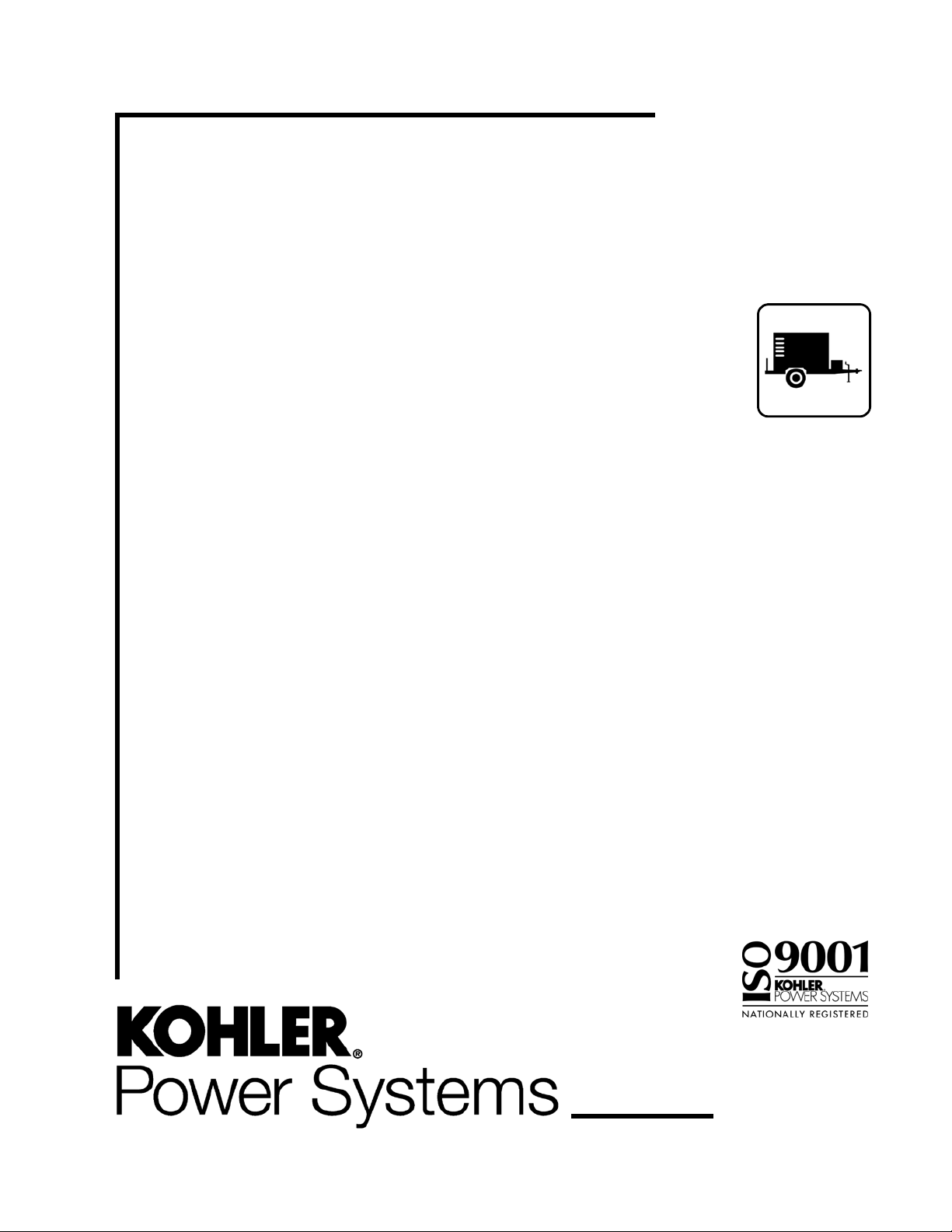
Hazardous Voltage/
Moving Parts
Hazardous voltage.
Will cause severe injury or death.
Disconnect all power sources before
opening the enclosure.
DANGER
Hazardous voltage.
Will cause severe injury or death.
This equipment must be installed and
serviced by qualified electrical
personnel.
DANGER
Hazard of electric shock,
explosion, or arc flash.
Will cause severe injury or death.
The enclosure should be opened by
trained and authorized personnel
only. Any terminal may be energized
when any cable is connected. Do not
connect or disconnect cables under
load. De-energize all cables at
generator prior to opening the cover.
DANGER
Hazardous voltage.
Will cause severe injury or death.
Multiple power sources can
automatically energize the
distribution bus. Disconnect all
power sources before connecting to
the distribution bus.
DANGER

TT-1672 10/166 Safety Precautions and Instructions
Grounding electrical equipment.
Hazardous voltage can cause
severe injury or death. Electrocution
is possible whenever electricity is
present. Ensure you comply with all
applicable codes and standards.
Electrically ground the generator set
and related equipment and electrical
circuits. Turn off the main circuit
breakers of all power sources before
servicing the equipment. Never
contact electrical leads or appliances
when standing in water or on wet
ground because these conditions
increase the risk of electrocution.
Connecting the battery and the
battery charger. Hazardous voltage
can cause severe injury or death.
Reconnect the battery correctly,
positive to positive and negative to
negative, to avoid electrical shock and
damage to the battery charger and
battery(ies). Have a qualified
electrician install the battery(ies).
Hazardous voltage.
Backfeed to the utility system can
cause property damage, severe
injury, or death.
If the generator set is used for
standby power, install an automatic
transfer switch to prevent inadvertent
interconnection of standby and
normal sources of supply.
WARNING
Electrical backfeed to the utility.
Hazardous backfeed voltage can
cause severe injury or death. Install
a transfer switch in standby power
installations to prevent the connection
of standby and other sources of power.
Electrical backfeed into a utility
electrical system can cause severe
injury or death to utility personnel
working on power lines.
Heavy Equipment
Unbalanced and elevated weight.
Improper lifting can cause severe
injury or death and equipment
damage.
Alwaysmaintainasafedistancefrom
the unit being lifted. Never stand
under a unit. Use lifting bars inserted
through the skid or the lifting eye to lift
the paralleling box.
WARNING
Hot Parts
Hot surfaces.
CAUTION

TT-1672 10/16 7Introduction
Introduction
This manual contains installation, setup, and
maintenance information for the Mobile Paralleling Box.
Use the paralleling box to connect two Kohler mobile
generator sets equipped with the
Decision-Makerr3500 controller for parallel operation.
The generator sets must have the same voltage and
phase configuration, but can be different models and
use different fuel types (for example, one diesel and one
LPG unit can be used).
Up to four paralleling boxes and eight generator sets can
be connected in one paralleling system.
The information included in this manual is intended
solely for use by trained and qualified service personnel
of authorized service distributors/dealers.
Information in this publication represents data available
at the time of print. Kohler Co. reserves the right to
change this literature and the products represented
without notice and without any obligation or liability
whatsoever.
GM88594
Figure 1 Paralleling Box GM88594-KP1-QS
Read this manual and carefully follow all procedures
and safety precautions to ensure proper equipment
operation and to avoid bodily injury. Read and follow the
Safety Precautions and Instructions section at the
beginning of this manual. Keep this manual with the
equipment for future reference.
The equipment service requirements are very important
for safe and efficient operation. Inspect parts often and
perform required service at the prescribed intervals.
Obtain service from an authorized service
distributor/dealer to keep equipment in top condition.
List of Related Materials
The paralleling box covered in this manual is one part of
a paralleling system. Refer to the operation manual
provided with the generator sets for detailed paralleling
information and instructions. The following list shows
additional literature relevant to the paralleling system.
Document Part Number
Specification Sheet, Paralleling Box G6-148
Generator Set Operation Manual,
Model REOZT4 TP-6895
Generator Set Operation Manual,
Model REZGT TP-6935
SiteTechtSoftware Operation Manual TP-6701

TT-1672 10/168 Service Assistance
Service Assistance
For professional advice on generator set power
requirements and conscientious service, please contact
your nearest Kohler distributor or dealer.
DConsult the Yellow Pages under the heading
Generators—Electric.
DVisit the Kohler Power Systems website at
KOHLERPower.com.
DLook at the labels and decals on your Kohler product
or review the appropriate literature or documents
included with the product.
DCall toll free in the US and Canada 1-800-544-2444.
DOutside the US and Canada, call the nearest regional
office.
Headquarters Europe, Middle East,Africa
(EMEA)
Kohler Power Systems Netherlands B.V.
Kristallaan 1
4761 ZC Zevenbergen
The Netherlands
Phone: (31) 168 331630
Fax: (31) 168 331631
Asia Pacific
Power Systems Asia Pacific Regional Office
Singapore, Republic of Singapore
Phone: (65) 6264-6422
Fax: (65) 6264-6455
China
North China Regional Office, Beijing
Phone: (86) 10 6518 7950
(86) 10 6518 7951
(86) 10 6518 7952
Fax: (86) 10 6518 7955
East China Regional Office, Shanghai
Phone: (86) 21 6288 0500
Fax: (86) 21 6288 0550
India, Bangladesh, Sri Lanka
India Regional Office
Bangalore, India
Phone: (91) 80 3366208
(91) 80 3366231
Fax: (91) 80 3315972
Japan, Korea
North Asia Regional Office
Tokyo, Japan
Phone: (813) 3440-4515
Fax: (813) 3440-2727

TT-1672 10/16 9Section 1 Specifications and Features
Section 1 Specifications and Features
1.1 Introduction
Different operation modes are possible with paralleled
generator sets. Review the brief descriptions below and
refer to the generator set Operation Manual for
complete operation information. Determine which
operation mode is needed for your application.
1.1.1 Generator Management Mode
In generator management mode, one generator set may
shut down if the load is small and start again if the load
increases. Generator management sequences the
generator sets off in a predetermined order. Generator
management must be enabled on all generator sets for
this mode of operation.
If generator management is disabled, all the generator
sets will run when a start signal is received.
Some sites may require generator management, and
others may prohibit it. If generator management is not
requested, it should be disabled.
Start the generator sets by holding AUTO and pressing
RUN to start in generator management mode.
1.1.2 Redundant Mode
Press the RUN button on each generator set to run the
generator sets without generator management. The
generator sets run continuously, independent of the
load. If one generator set shuts down, the others
continue to run and supply the load.
1.1.3 Load Management
Most paralleling applications require some type of load
management. Load management allows the removal of
non-critical loads in order to prevent overload of a
generator set if one or more generator sets are out of
service or otherwise unavailable. Large loads that are
not critical to human health and safety or the operation of
the facility are good candidates for load management.
The Decision-Makerr3500 controller supports 6 load
priorities. Priority 1 adds first and sheds last. Priority 6
adds last and sheds first. The priorities are shared
throughout the paralleling system, meaning that priority
1 will shed simultaneously on all controllers, regardless
of the generator set state (running or stopped). See the
generator set operation manual for additional
information.
Connection of 1 -- 3 priorities to each generator provides
better redundancy than connecting all priorities to a
single generator.
1.2 Paralleling Box Features
DWater-resistant enclosure designed and tested to
NEMA type 3R enclosure specifications for outdoor
installation
DSix inch high skid with forklift openings
DSingle point lifting eye
DIndicator lights (ON when generator set is connected
to the bus)
DColor-coded camlock power connectors
DLockable security bars for unused input and output
camlock connectors
DCable strain-relief tie-down points
DControl harnesses, two provided with each
paralleling box
DCooling fans
DStorage locker with keyed latch and rack for control
harnesses
DExternal ground lug
DRemovable neutral/ground bonding bus for
application flexibility
DPadlock hasp for electrical compartment security
See ADV-8713 in Section 7 for paralleling box
dimensions and features.

TT-1672 10/1610 Section 1 Specifications and Features
1.3 Requirements
Paralleled generator sets:
DMust be mobile models REOZT4 or REZGT equipped
with the Decision-Makerr3500 controller, voltage
selector switch, and camlock connectors.
DMust have the same voltage configuration and
number of phases (all single--phase or all
three-phase).
DMust have the control harness connector shown in
Figure 1-1. Install the retrofit kit, if necessary. See
Figure 1-2 for kit numbers.
DCan be different kW models. For example, you can
parallel one 35REOZT4 with one 175REOZT4.
DCan use different fuels (for example, one LPG
generator set and one diesel unit).
The paralleling box is not intended for permanent
stationary use.
1
GM91197
1. Control harness connector
Figure 1-1 Control Harness Connector
Generator Set Model Adapter Kit Number
30--125REZGT GM98565--S
35/45REOZT4 GM98566--S
Figure 1-2 Generator Set Retrofit Kits
1.4 Specifications
Paralleling Box Specifications
Source Input Voltage Range 120--600 VAC
Load Output voltage Range 120--600 VAC
Source Current Limit 1000 amps each (max.) *
2000 amps total (max.) *
Output Bus Sensing 120--600 VAC (fused)
Contactor Coil 208--240 VAC
1200 W max.
Control Harness Length [7.6 m (25 ft.)
* Derate 5% per 10_C(18_F) above 40_C (104_F).
[Two (2) control harnesses are factory-supplied with each box.
Figure 1-3 Electrical Specifications
Environmental Specifications
Operating Temperature --5to55_C (23 to 131_F)
Storage Temperature --40 to 70_C (--40 to 158_F)
Humidity 5% to 95%
Figure 1-4 Environmental Specifications
Weight and Dimensions
Weight, kg (lbs.) * 408 (900)
Dimensions, L x W x H mm (in.) 1067 x 1067 x 1431
(42.0 x 42.0 x 56.3)
* Approximate weight
Figure 1-5 Weight and Dimensions
1.5 System Installation Overview
and Interconnection Diagram
The figures in this section are intended to give an
overview of the paralleling system installation and
connections. They are not intended to replace the more
detailed instructions given later in this manual. Be sure
to read and follow all instructions and safety precautions
in the next sections of this manual.
Figure 1-6 summarizes the installation procedure for
the paralleling system. Each step refers to a section of
this manual or the generator set documentation. Be
sure to read and follow all instructions for each step.
Figure 1-7 shows an overall view of the paralleling
system. Two to eight generator sets can be paralleled
using one to four paralleling boxes. Be sure to follow the
safety precautions and instructions in Section 4 for all
electrical connections.

TT-1672 10/16 11Section 1 Specifications and Features
If the generator sets are not equipped with the control
harness connector shown in Figure 1-1, install the retrofit
harness. *
Connect load cable cam-lock connectors.
Connect source cable camlock connectors from generator sets
to the paralleling box.
On one generator set, hold AUTO and press RUN. Release
RUN first and then release AUTO.
Press AUTO on each generator set to place all generator
sets in AUTO mode.
Verify operation for each generator set in the system.
Verify that all generator sets start and one contactor closes.
Then the other generator sets synchronize and all other
contactors close.
Install generator sets and place the paralleling box within 20
feet of both generator sets.
Follow the instructions provided in the
generator set manuals. See Section 2.3 for
paralleling box location requirements.
See Section 4.7.
For multiple paralleling boxes, connect PGEN communication
wiring. * See Section 4.9 in this manual.
Follow the test procedure in Section 4.11 for
each generator set.
Verify that % of rated power is the same for all generator
sets, showing that the load is shared proportionally.
* Steps shown in shaded gray boxes may not apply to all applications.
Connect power/ control harness from each generator set to
paralleling box. See Section 4.8.
See Section 1.3 and follow the instructions
provided with the harness.
See Section 4.6.
Ground the paralleling box. See Section 4.5.
Perform the system setup procedure in Section 3.3. See Section 3.3.
If possible, test the system under load using a load bank or
the actual load.
Figure 1-6 System Installation Overview

TT-1672 10/1612 Section 1 Specifications and Features
PGEN CABLE FOR
MULTIPLE BOXES
(CUSTOMER SUPPLIED
BELDEN #9841 OR
EQUIVALENT)
NOTE:
N = NUMBER OF PARALLELING BOXES.
MAXIMUM NUMBER OF PARALLELING BOXES IS 4.
MAXIMUM NUMBER OF GENERATOR SETS IS 8.
CONTROL HARNESS
(SUPPLIED WITH
PRODUCT, QTY. 2)
Figure 1-7 System Interconnection Diagram

TT-1672 10/16 13Section 2 Transportation and Location
Section 2 Transportation and Location
2.1 Introduction
Read and follow the safety precautions included in this
manual. Pay attention to the decals on the equipment
and follow the instructions in this manual.
All personnel involved in handling, site preparation,
installation, testing, operation, and maintenance should
be thoroughly familiar with the information in this manual
and the customer drawings provided before working
with this equipment.
2.2 Lifting and Transporting
Unbalanced and elevated weight.
Improper lifting can cause severe
injury or death and equipment
damage.
Alwaysmaintainasafedistancefrom
the unit being lifted. Never stand
under a unit. Use lifting bars inserted
through the skid or the lifting eye to lift
the paralleling box.
WARNING
Use a truck or utility trailer of sufficient size to transport
the unit. The box dimensions and weight are shown in
Section 1.1.
The paralleling box can be lifted with a fork lift. Note the
unit’s weight shown in Section 1.1. Insert the forks
through the openings in the skid.
The paralleling box is also equipped with a lifting eye for
lifting and stabilizing the box. Use lifting equipment that
is rated for the weight of the box.
2.3 Location
The paralleling box and connected generators make up
the power system. Use the following information as a
guideline when selecting a location for the paralleling
box. Be aware of potential detrimental conditions and
use common sense when determining a location. The
contractor, property owner, and/or power system owner
must address the issues of security and personnel
safety in areas that are open to the public and occupied
by children.
2.3.1 Generator Set Proximity
The paralleling box must be installed near the generator
sets. Install the paralleling box within 6 m (20 ft) of the
generator sets to allow connection of the 7.6-meter
(25-foot) long control harness. A minimum clearance of
0.6 m (2 ft.) between the generator sets and the
paralleling box is recommended for sufficient cooling air
flow.
2.3.2 Surface Stability
Choose a location with a solid, level base and avoid
loose gravel, soft dirt, mud, standing water, etc. Avoid
steep dropoffs, rough terrain, etc. If the area is subject to
heavy rain, evaluate the surrounding area to avoid
flooding and/or mud damage.
2.3.3 Adequate Air Flow/Heat
Dissipation
Select a location that provides adequate air flow. Avoid
locations next to tall buildings that block normal air flow
and cause air vacuum pockets. Avoid areas subject to
high winds, excessive dust, or other airborne
contaminants. Select a shaded area away from direct
sunlight and/or other heat producing equipment when
practical.
2.3.4 Combustible Materials
Avoid areas with combustible materials, including
building materials as well as natural surroundings. Keep
dry field grass, foliage, and combustible landscaping
material a safe distance from the generator set exhaust
systems. DO NOT locate the power system or operate
the generator set in an environment with explosive
fumes.

TT-1672 10/1614 Section 2 Transportation and Location
Notes

TT-1672 10/16 15Section 3 Prestart Checks and Paralleling Setup
Section 3 Prestart Checks and Paralleling Setup
3.1 Prestart Checklist
Perform the prestart checks listed in the generator set
operation manual. In addition to those generator set
items, check the following on the paralleling box before
startup and at regular intervals.
Air Inlets. Check for clean and unobstructed air inlets.
Enclosure Doors. Check that the service access doors
are closed and secured.
Fire Extinguisher (user-supplied). Verify that a fully
charged fire extinguisher that is rated for electrical fires
is in place.
Operating Area. Check for obstructions that could
block the flow of cooling air. Keep the area clean. Do not
leave rags, tools, or debris on or near the equipment.
3.2 Weather and Climate
Provisions and Operation
Limitations
Operation and use of a generator set in the outdoors or
in unsheltered areas require special attention to
weather conditions and environmental surroundings.
Weather conditions may limit the usability where rain or
damp conditions increase the chance of electrocution.
A generator set, like any other electromechanical
device, can pose potential dangers to life and limb if
improperly maintained or operated. The best way to
prevent accidents is to be aware of potential dangers
and act safely. This manual and the generator set
operation manual contain several types of safety
precautions and instructions. Please read and follow
the safety precautions and instructions to prevent harm
to yourself and others.
Operate the generator set during rain or other inclement
weather conditions only if the responsible electrician
and/or contractor can secure and protect electrical
connections from inclement weather exposure. Keep
the trailer doors closed and all electrical boxes closed.
Keep unauthorized personnel away from all electrical
wiring and devices. The responsible electrician and/or
contractor must maintain periodic inspection of the
generator set and electrical devices during inclement
weather conditions.
If at any time there is a question of generator set
operation suitability during inclement weather, shut
down the generator set immediately.
3.3 Paralleling System Setup
Use a personal computer with SiteTechtsoftware
connected to the generator set controller to configure
each generator in the paralleled system. Some settings
can also be checked and adjusted using the
Decision-Makerr3500 controller menus. The controller
settings are summarized in Figure 3-1 at the end of the
procedure.
Refer to the operation manual provided with the
generator set for Decision-Makerr3500 controller
instructions. The generator operation manual also
contains detailed information about paralleling setup
and operation, including synchronization, generator
management, and load management (load control).
1. Check that the generator set voltage selector
switch and/or alternator wiring matches the voltage
configuration for the building (or loads being
supplied). Repeat for all generator sets in the
system.
2. Set the digital output to Contactor.
In SiteTech go to Programmable Digital Output 116
and set the Digital Output Event to Contactor.
This setting can be checked but not changed on the
Decision-Makerr3500 controller. Go to I/O >
DIGITAL OUTPUT > DIGITAL OUTPUT 1:2
Repeat for all generator sets in the system.
3. Set the reactive droop to 0.5 – 2%. The default
setting of 1% works in nearly all applications. Use
the same reactive droop setting on all generators in
the paralleled system.
In SiteTech go to Reactive Power Sharing and set
the reactive droop slope.
On the Decision-Makerr3500 controller go to:
GENERATOR INFO > VOLTAGE REGULATION
(called VOLT DROOP AT 100% kVAR), or
GENERATOR INFO > PARALLELING
OPERATION > SHARING SETUP
4. Set the target voltage on all paralleled generators
to the same value.
In SiteTech go to Voltage Regulator and set
Voltage Regulator Average Voltage Adjustment.
On the Decision-Makerr3500 controller go to:
GENERATOR INFO > VOLTAGE REGULATION
5. Set the engine speed adjustment to 50 on all
generators. The engine speed adjustment setting
must be the same on all generators in the system.
In SiteTech, go to Engine Speed Governor and set
the Engine Speed Adjustment.

TT-1672 10/1616 Section 3 Prestart Checks and Paralleling Setup
On the Decision-Makerr3500 controller, go to
GENERATOR INFO > CONFIGURATION >
GENERATOR CONFIG.
Note: 50 is the default setting, which sets the
engine speed to the nominal engine speed
(for example, 1800 RPM). Settings between
40 and 60 are acceptable. A setting of 52
increases the engine speed by 2 RPM; 49
decreases the engine speed by 1 RPM; etc.
6. Verify metering. Check the voltage displayed on
the generator set controller. If it is not correct, go to
the calibration procedure in Section 3.4.
Repeat for all generator sets in the system.
7. For all generators in the system, set the Sync Mode
in AUTO setting to ACTIVE. Set the Sync Mode in
Run setting to CHECK. Synch mode settings are
summarizedinFigure3-2.
In SiteTech, go to Synchronization Control and set
the Sync Mode in AUTO and Sync Mode in Run
settings.
On the Decision-Makerr3500 controller, go to
GENERATOR INFO > PARALLELING
OPERATION > SYNCHRONIZING SETUP.
Note: When the generators are in AUTO mode,
the ACTIVE setting will actively adjust the
speed and voltage of the generator in order
to synchronize with the paralleling bus and
close the contactor in the paralleling box as
soon as synchronization is maintained for a
minimum length of time (which is set by the
dwell timer). For other synchronization
mode options, see Figure 3-2.
8. Set Generator Management Enabled to OFF at
each generator set unless generator management
is requested for the application. See the generator
operation manual for detailed information about
generator management.
In SiteTech, go to Generator Management and set
Gen Management Enabled ot OFF.
On the Decision-Makerr3500 controller, go to
GENERATOR INFO > PARALLELING
OPERATION > GENERATOR MANAGEMENT.
Note: Generator management must be disabled
manually at each generator set controller.
9. Set up load management for non-critical loads. Set
the Load Shed Priority for each load. Priority 1
adds first and sheds last.
In SiteTech, go to Programmable Digital Output
115 and set the Digital Output Event to Load
Priority (1--6) Shed.
On the Decision-Makerr3500 controller, go to
GENERATOR INFO > PARALLELING
OPERATION > LOAD CONTROL
Note: Load shed relays are required for load
management. See the generator set
documentation for relay connection
information.
Note: The generator sets must be in AUTO mode
for load management operation.
10. Stop all generators by pressing the OFF button on
each controller.

TT-1672 10/16 17Section 3 Prestart Checks and Paralleling Setup
Parameter Recommended Setting DEC 3500 Menu SiteTech Menu
Digital Output Contactor I/O > DIGITAL OUTPUT >
DIGITAL OUTPUT 1:2
(verification only)
Programmable Digital Output
116 Menu
Digital Output Event
Reactive Droop Default setting = 1%.
Range 0.5 -- 2%.
GENERATOR INFO >
VOLTAGE REGULATION
(called VOLT DROOP AT
100% kVAR)
or
GENERATOR INFO >
PARALLELING OPERATION
> SHARING SETUP
Reactive Power Sharing
Menu
Reactive Droop Slope
Target Voltage Rated voltage.
Set the target voltage on each
generator to the same value.
GENERATOR INFO >
VOLTAGE REGULATION
Voltage Regulator Menu
Voltage Regulator Average
Voltage Adjustment
Engine Speed Adjustment Default setting = 50
Range 40--60
GENERATOR INFO >
CONFIGURATION >
GENERATOR CONFIG.
Engine Speed Governor
Menu
Engine Speed Adjustment
Sync Mode in Auto * Active GENERATOR INFO >
PARALLELING OPERATION
> SYNCHRONIZING SETUP
Synchronization Control
Menu
Sync Mode in AUTO
Sync Mode in Run * Check GENERATOR INFO >
PARALLELING OPERATION
> SYNCHRONIZING SETUP
Synchronization Control
Menu
Sync Mode in Run
Generator Management OFF GENERATOR INFO >
PARALLELING OPERATION
> GENERATOR
MANAGEMENT
Generator Management
Menu
Gen Management Enabled
Load Management Load Priority 1 Shed
Load Priority 2 Shed
Load Priority 3 Shed
Load Priority 4 Shed
Load Priority 5 Shed
Load Priority 6 Shed
GENERATOR INFO >
PARALLELING OPERATION
> LOAD CONTROL
Programmable Digital Output
115 Menu
Digital Output Event
* See Figure 3-2 for other Sync Mode settings.
Figure 3-1 Decision-Makerr3500 Settings for Paralleling

TT-1672 10/1618 Section 3 Prestart Checks and Paralleling Setup
Sync Mode Setting Description
Sync Mode in Auto Sync Mode in Auto is the synchronization mode that the controller uses when the engine control
switch is in AUTO, as indicated by the blue indicator over the AUTO button. This Sync Mode
defaults to Active, which will work for almost all applications.
Sync Mode in Run Sync Mode in Run is the synchronization mode that the controller uses when the engine control
switch is in RUN, as indicated by the blue indicator over the RUN button. If the generators will be
primarily operated by pressing the RUN button on each generator, this sync mode should be set
to Active.
Off The controller does not attempt to synchronize in any way.
Check The controller actively controls the speed and voltage of the generator in an effort to synchronize
with the paralleling bus, but doesn’t close the contactor in the paralleling box unless no other
generators are powering the bus.
Passive The controller does not attempt to synchronize in any way, but if it remains in phase with the
paralleling bus for the duration of the dwell timer, it will close the paralleling contactor. This mode
is used when the controller is unable to adjust engine speed or can only adjust engine speed to a
higher speed.
Active The controller actively controls the speed and voltage of the generator in order to synchronize
with the paralleling bus, closing the contactor in the paralleling box as soon as it is synchronized
for the duration of the dwell timer.
Figure 3-2 Synchronization Mode Settings

TT-1672 10/16 19Section 3 Prestart Checks and Paralleling Setup
3.4 Calibration
Note: Copying personality profiles from one controller
to another can overwrite the calibration
coefficients. This requires re-calibrating the
controller, which is often easier than attempting to
change all the settings twice.
Line-to-line voltage calibration is important for good
system performance. Paralleling compares line-to-line
voltages (generator and paralleling bus), and the
voltage regulator also regulates to line-to-line voltage.
For wye-connected systems, line-to- neutral voltage
should also be calibrated for correct power metering.
Generator Voltage: The generator set controllers must
be calibrated to ensure that they are measuring voltage
correctly in order to produce the correct output voltage.
The controller uses the measured voltage to match the
three-phase average voltage to the target. If the
measured voltage is incorrect, the generator will not
produce the correct target voltage.
Bus Voltage. During synchronization, the controller
matches the generator voltage to the measured bus
voltage to ensure that the reactive power exchange is a
minimum when the breaker closes. If the bus metering is
not calibrated correctly, the Decision-Makerr3500
controller will match the generator voltage to the
incorrect bus voltage. If the measured bus voltage is
either higher or lower than the actual bus voltage, it will
result in reactive power transfer when the breaker
closes, potentially causing a generator to disconnect
from the paralleling bus to protect itself.
A multimeter with a recent calibration verification is
necessary to calibrate the generator controller. The
controller should be within 2% accuracy without
calibration. Using an uncalibrated meter could make the
controller less accurate than it was before calibration.
1. Calibrate the Generator Voltage
Generator voltage is calibrated most easily from
the front panel of the controller. Use a calibrated
multimeter to measure the generator voltage and
enter the correct value in the CONTROLLER
CONFIG -> CALIBRATION screen on the
controller.
2. Calibrate the Bus Voltage
Bus voltage is calibrated most easily from the front
panel of the controller. Use a calibrated multimeter
to measure the bus voltage and enter the correct
value in the CONTROLLER CONFIG ->
CALIBRATION screen on the controller.

TT-1672 10/1620 Section 3 Prestart Checks and Paralleling Setup
Notes
Table of contents
Other Kohler Accessories manuals

Kohler
Kohler 8787T-B01 User manual

Kohler
Kohler K-8872T-C01 User manual

Kohler
Kohler 24146IN-7 User manual

Kohler
Kohler K-EX27460T-NW-CP User manual

Kohler
Kohler K-8787X-B03 Assembly instructions

Kohler
Kohler GM87026-KP1-WHT User manual

Kohler
Kohler K-4709 Assembly instructions

Kohler
Kohler 1019439 Manual

Kohler
Kohler Bardon K-8787T-C01 User manual

Kohler
Kohler K-EX29936T-N-CP User manual
Popular Accessories manuals by other brands

Spinball Sports
Spinball Sports Wizard owner's manual

VOLTCRAFT
VOLTCRAFT SL-4F operating instructions

Hyundai
Hyundai WS SENZOR 1070 instruction manual

Pico Macom
Pico Macom MPCD Installation and operation manual

Dräger Medical
Dräger Medical 8000 IC Calibration & Testing

Colortrac
Colortrac SingleSensor CIS instruction manual