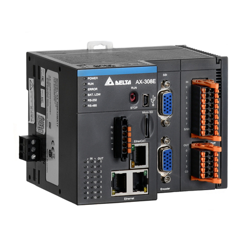
Delta CMM-DN01 User manual

i
CMM-DN01/CMM-
DN02 DeviceNet
CMM-DN01/02 DeviceNet Slave Station
Communication Module Operation Manual
Applicable Products:
CMM-DN01 / CMM-DN02 (MS300 / MH300 Option Cards)
Application Drive Firmware Version: MS300 V1.07 / MH300 V1.02 or later
CMM-DN02 Communication Card Firmware Version: V1.01 or later
DELTA_IA-MDS_VFD-M300 Series_CMM-DN02_OM_EN_20230616

ii
Copyright notice
©Delta Electronics, Inc. All rights reserved.
All information contained in this user manual is the exclusive property of Delta Electronics
Inc. (hereinafter referred to as "Delta ") and is protected by copyright law and all other laws.
Delta retains the exclusive rights of this user manual in accordance with the copyright law
and all other laws. No parts in this manual may be reproduced, transmitted, transcribed,
translated or used in any other ways without the prior consent of Delta.
Limitation of Liability
The contents of this user manual are only for the use of the AC motor drives manufactured
by Delta. Except as defined in special mandatory laws, Delta provides this user manual “as
is” and does not offer any kind of warranty through this user manual for using the product,
either express or implied, including but not limited to the following: (i) this product will meet
your needs or expectations; (ii) the information contained in the product is current and
correct; (iii) the product does not infringe any rights of any other person. You shall bear your
own risk to use this product.
In no event shall Delta, its subsidiaries, affiliates, managers, employees, agents, partners
and licensors be liable for any direct, indirect, incidental, special, derivative or consequential
damages (including but not limited to the damages for loss of profits, goodwill, use or other
intangible losses) unless the laws contain special mandatory provisions to the contrary.
Delta reserves the right to make changes to the user manual and the products described in
the user manual without prior notice and afterwards.

Caution
This operation manual provides information on specifications, installation instructions,
basic operations/configurations, and details on network communication protocols.
This model uses the OPEN TYPE case. So, you must install it in a dustproof,
moisture-proof, and shockproof enclosure when using this motor drive. This enclosure
must be protected by special tools or keys to prevent non-maintenance personnel
from operating or accidental impact on the unit, which may cause danger and
damage. Do not touch any terminals while powering up.
Read this manual carefully and follow the instructions completely to avoid device
damage or personal injury.

Table of Contents
Chapter 1 Introduction to CMM-DN01/CMM-DN02 ………………………………………………1-1
1.1 Product Features ………………………………………………………………………………1-2
1.2 Specifications
Chapter 2 DVPDNET-SL Components….………………………………………………………………2-1
2-1 Components Overview………………………………………………..…………………………2-2
2-2 DeviceNet Connection Terminals ………………………………………………………..……2-2
Chapter 3 CMM-DN01/CMM-DN02 Basic Function ……………………………………………3-1
3.1 Installation and Wiring………………………………………………………………………..…3-2
Chapter 4 Relations between MS300 series Motor Drives and Device Net Master Stations 4-1
4.1 DeviceNet Data Exchange………………………………………………………………………4-2
4.2 Mapping of CMM-DN01/CMM-DN02 Communication Cards……………………………4-2
4.3 Building I/O Connection………………………………………………………………………4-4
Chapter 5 Build a DeviceNet Network ……………………………………………5- 1
5.1 Build a DeviceNet Network via CMM-DN01/ CMM-DN02 Communication Cards ………5-2
5.2 Use DeviceNet Builder Software to Configure the Network ………………………………5-3
5.3 Corresponding Mapping Relationship ………………………………………………………5-12
5.4 Editing the ladder diagram ……………………………………………………………………5-12
Chapter 6 Fault Codes Displayed on the Keypad ……………………………………………………6-1
6.1 Fault Codes on the Keypad……………………………………………………….………6-2
Chapter 7 LED Indicator Lights and Troubleshooting………………………………………………7-1
7.1 Power LED Description………………………………………………………………………7-2
7.2 NS LED Description………………………………………………………………7- 2
7.3 MS LED Description………………………………………………………………7-3
Appendix A. Supporting DeviceNet Object……………………………………………………………A-1
A.1. DeviceNet objects List ……………………………………………………………………A-2
A.1.1 Class 0x01 – Identity object ………………………………………………A- 2
A.1.2 Class 0x02 – Message router object ………………………………………………A-3
A.1.3 Class 0x03 – DeviceNet object ………………………………………………………A-3
A.1.4 Class 0x05 – Connection object ……………………………………………………A-4
A.1.5 Class 0x96 Parameter Object ………………………………………………………A-5
A.1.6 Class 0x95 – DataConf Class attribute ……………………………………………A-6
Issued Edition: 00
Issued Date: June 2023

1-1
1
Chapter 1 Introduction to CMM-DN01/CMM-DN02
1.1 Product Features
1.2 Functions

CMM-DN01/02 Device Net Slave Station Communication Module Operation Manual
1-2
_1
Thank you for using Delta CMM-DN01/CMM-DN02 network communication module. In order to make
sure that you can install and operate properly this product, read this user manual carefully before
starting to use this module.
CMM-DN01/CMM-DN02 is a DeviceNet network communication module, which can be controlled
remotely to set up communication functions via the DeviceNet bus.
CMM-DN01/CMM-DN02 communication cards are used to connect Delta VFD-MS300/VFD-MH300
series AC motor drives to the DeviceNet networks.
The CMM-DN01/CMM-DN02 communication card will be described in detail below.
1.1.
Product Features
Based on the high-speed communication interface of Delta’s HSSP protocol, the AC motor drive can be
controlled in real-time.
Supports Group 2 only connection and polling I/O data exchange.
For I/O mapping, supports a maximum of 32 words input and 32 words output.
Supports EDS file configuration in DeviceNet configuration software.
Supports all baud rates on DeviceNet bus: 125 kbps, 250 kbps, 500 kbps and extendable baud rate
mode.
Node address and baud rate can be set in the AC motor drive.
Power is supplied from the AC motor drive.
1.2.
Specifications
DeviceNet Connector
Item
Specification
Interface
5-PIN open pluggable connector. PIN interval: 5.08mm
Communication Mode
CAN
Transmission cable
Shielded twisted-pair cable (with 2 power cables)
Transmission Speed
125 kbps, 250 kbps, 500 kbps and extendable baud rate mode
Communication Protocol
DeviceNet protocol
AC Motor Drive Connection Port
Item
Specification
Interface 24 PIN communication terminal
Communication Mode SPI communication
Terminal function
1. Communication modul
e communicates with the AC motor drive
through this port.
2. The AC motor drive supplies power to communication module through
this port.
Communication Protocol Delta HSSP protocol

Introduction to CMM-DN01 / CMM-DN02
1_
Environment Conditions
Item Specification
Noise immunity
ESD (IEC 61800-5-1, IEC 6100-4-2)
EFT (IEC 61800-5-1,IEC 6100-4-4)
Surge Teat (IEC 61800-5-1,IEC 6100-4-5)
Conducted Susceptibility Test (IEC 61800-5-1, IEC 6100-4-6)
Operation / storage
Operation: -10–50°C (temperature), 90% (humidity)
Storage: -25–70°C (temperature), 95% (humidity)
Shock / vibration resistance
International Standard Specification IEC 61800-5-1, IEC 60068-2-6 /
IEC 61800-5-1, IEC 60068-2-27
Electrical Specifications
Item Specification
Power Voltage 5VDC (Supplied by the AC motor drive)
Insulation Voltage 500VAC
Communication cable power
consumption 0.85W
Power consumption 1W
Weight 23g

2-1
2
Chapter 2 Components of CMM-DN01/CMM-DN02
2.1 Components Overview
2.2 DeviceNet Connection Ports

CMM-DN01/02 DeviceNet Slave Station Communication Module Operation Manual
2-2
_2
2.1 Components Overview
Fig,2.1.1 Front View Fig.2.1.2 Rear View
1 Screw fixing hole 2 Positioning hole 3
AC motor drive
connection port
4 Communication Port 5
LED Indicator NET1 (MS),
NET2 (NS)
6 POWER indicator
7
Ground terminal block
2.2 DeviceNet Connector
Use this port to connect to the DeviceNet network. The table below show its PIN definitions:
PIN
Signal
Color
Description
1
V+
Red
DC24V
2
H
White
Positive signal
3
S
-
Ground
4
L
Blue
Negative signal
5 V- Black 0V

3-1
3
Chapter 3 Basic Operation
3.1 Installation and Wiring

CMM-DN01/02 DeviceNet Slave Station Communication Module Operation Manual
3-2
_3
3.1 Installation and Wiring
Wiring Cables
Description
Figure
①
Use a professional tool to strip the
communication cable by about 30mm, and
make sure not to damage the shielded wire
during the stripping process.
Approx. 30mm
②
Peel off the outer metal shield mask and
aluminum foil and you will see 2 power lines
(red and black), 2 signal lines (blue and
white), and 1 shielded line
Shielded cable
③
Remove the outer layer of metal shield and
aluminum foil, then peel off the plastic skin of
the power cable and the signal cable to an
appropriate length.
④
Insert the stripped communication cable in
the correct order into the wiring holes of the
communication connector as shown in the
figure on the right.
Black (V-)
Blue (CAN_L)
Shielded cable (CAN_SHLD)
Red (V+)
White (CAN_H)
⑤
Use a standard slotted/flat head screwdriver
to tighten the communication connector
screws and secure the communication cable
in the wiring holes of the communication
connector.
Screw by a slotted
screwdriver

Chapter 3 CMM-DN01 / CMM-DN02 Basic Function
3-3
3_
Mounting Position of Option Card
Frame A–D Mounting position 1, 2 (Option card mounting
box)
Frame E and F Mounting
position 1
(Option card mounting box)
Figure 3-1
Figure 3-2
Note: Frame E and F does not support a second option card installation, so there is no mounting position 2.
The Wiring of Option Cards
MS300 control board connector
Option card connector
Figure 3-3
Figure 3-4
Attention: Do NOT misuse the cables for the
communication cards and the cables for the power
card. You must read the descriptions on the cables
before wiring.
Communication Card Cables
To correctly use the communication cards, you must purchase the communication card along with the
connection cables. Check your communication card models first. Then, select your applicable connection
cables according to the mounting positions by different frames. Two cable length are available for your choice.
See the table below to select your applicable communication card cables.

CMM-DN01/02 DeviceNet Slave Station Communication Module Operation Manual
3-4
_3
Applicable for MS300:
Communication
Cards
CMM-DN02; CMM-EIP02; CMM-EIP03;
CMM-PD02; CMM-COP02
CMM-EC02
Frame
Mounting Position 1
Mounting Position 2
Mounting Position
1
Mounting Position 2
Cable Model#
Cable Model#
Cable Model#
Cable Model#
A
CBM-CL01A
CBM-CC01A
CBM-CL01A
CBM-CL01A
B
CBM-CC02A CBM-CL02A
C
CBM-CL02A CBM-CL02A
D
E
N/A N/A
F
Table 3-1
Applicable for MH300
Communi
cation
Cards
CMM-DN02; CMM-EIP02;
CMM-EIP03
CMM-PD02, CMM-COP02
CMM-EC02
Frame
Mounting Position 1
Mounting Position 2
Mounting Position 1
Mounting Position 2
Cable Model#
Cable Model#
Cable Model#
Cable Model#
A
CBM-CL01A
CBM-CC01A
CBM-CL01A
CBM-CL01A
B
CBM-CC02A
CBM-CL02A
C
CBM-CL02A CBM-CL02A
D
E
CBM-CL02A
F
G
H
I
Table3-2
An option card mounting box is included upon purchasing the communication card CMM-EC02,
you need to purchase it with CBM-CL01A or CBM-CL02A
Model:
CBM-CL01A
CBM-CC01A
Figure 3-5
Model:
CBM-CL02A
CBM-CC02A
Figure 3-6

Chapter 3 CMM-DN01 / CMM-DN02 Basic Function
3-5
3_
Power Card Cables
An option card mounting box and cables with two different length are included when you purchase the power
card EMM-BPS02 (DC 24 V backup power supply card), so you do not need to purchase it with the connection
cables. “BPS use only” and “# S” or “# L” are marked on the EMM-BPS02 power card cable. See the table
below to select your applicable power card cables according to different mounting positions.
Applicable for MS300:
Power Card
EMM-BPS02
Frame
Mounting Position 1
Mounting Position 2
Cable Model#
Cable Model#
A
# S
# S
B
# L
C
# L
D
E
N/A
F
Table 3-3
Applicable for MH300:
Power
Card
EMM-BPS02
Frame
Mounting Position 1
Mounting Position 2
Cable Model#
Cable Model#
A
Expansion Card
# S
B
# L
C
D
E
F
G
H
I
Table 3-4
# S
Figure 3-7
# L
Figure 3-8

CMM-DN01/02 DeviceNet Slave Station Communication Module Operation Manual
3-6
_3
Mounting Position of Option Card 1
Installation method: Back-mount the option card by connecting flat cables to the control board.
1. Turn off the power of the motor drive, and then remove the front cover, as shown in Figure 3-8.
2. Assemble the connection cable: Connect the connector at one end of the connection cable to the control
board connector. Refer to Page 3-3 The Wiring of Option Cards for more information on connection
methods.
3. Assemble the supported frame of the option card: Aim the two clips at the two slots on the motor drive,
and then press downward to have the two clips engage the slots, as shown in Figure 3-9.
4. Assemble the connection cable: Connect the connector at the other end of the connection cable to the
connector of the option card.
5. Assemble the option card: Have the terminal block and connector of the option card face downward, aim
the two holes of the option card to the position column and press downward so that the three clips engage
the option card, as shown in Figure 3-10.
6. Make sure that three clips properly engage the option card and then tighten the screws (suggested torque
value: 4–6 kg-cm [3.5–5.2 lb-in.] [0.39–0.59 Nm]), as shown in Figure 3-11.
7. Assembly is completed, as shown in Figure 3-12.
Figure 3-8
Figure 3-9
Figure 3-10
Figure 3-11
Figure 3-12

Chapter 3 CMM-DN01 / CMM-DN02 Basic Function
3-7
3_
Option Card Mounting Position 2 (Frame A–D)
Installation method: Front-mount the option card by connecting flat cables to the control board.
1. Turn off the power of the motor drive, and then remove the front cover, as shown in Figure 3-13.
2. Assemble the option card: Detach the upper cover of the mounting box for the option card by slipping and
make the terminal block and connector of the option card face upward. Fix the front end of the option card
to the slots, and then rotate it, as shown in the Figure 3-14.
3. Make sure that two clips properly engage the option card on the backside, and then tighten the screws
(suggested torque value: 4–6 kg-cm [3.5–5.2 lb-in.] [0.39–0.59 Nm]), as shown in Figure 3-15.
4. Assemble the connection cable: Connect the connector at one end of the connection cable to the control
board connector. Refer to Page 3-3 The Wiring of Option Cards for more information on connection
methods.
5. Attach the front cover of the drive.
6. Assemble the connection cable: Connect the connector at the other end of the connection cable to the
connector of the option card.
7. Attach the upper cover to the mounting box for the option card, as shown in Figure 3-16.
8. Assemble the mounting box for the option card: Aim the four clips of the mounting box for the option card
at the slots on the upper cover of the motor drive, and then press downward to have the four clips engage
the slots, as shown in the Figure 3-17.
9. Assembly is completed, as shown in Figure 3-18.
Figure 3-13 Figure 3-14 Figure 3-15
Figure 3-16
Figure 3-17
Figure 3-18

CMM-DN01/02 DeviceNet Slave Station Communication Module Operation Manual
3-8
_3
Grounding installation
You must ground the option cards as listed below when wiring. The ground terminal is included in the
option card package, as shown in Figure 3-19.
Figure 3-19 Grounding Wire
Installation
The B end of the grounding wire connects to the ground terminal block of the option card, as the No.7
shows in Figure 3-20. The A end of the grounding wire connects to the drive’s PE, as the circles show in
Figure 3-21 and Figure 3-22.
Figure 3-20
Frame
A–C
Figure 3-21
Frame
D–F
Figure 3-22
A End
B End

Chapter 3 CMM-DN01 / CMM-DN02 Basic Function
3-9
3_
Frame
Screw Torque (±10%)
Frame
Screw Torque (±10%)
A
M3.5
9 kg-cm [7.8 lb-in] [0.88 Nm]
D
M4
20kg-cm [17.4lb-in] [1.96Nm]
B
M4
15kg-cm [13.0lb-in] [1.47Nm]
E
M5
25kg-cm [21.7lb-in] [2.45Nm]
C
M4
20kg-cm [17.4lb-in] [1.96Nm]
F
M4
20kg-cm [17.4 lb-in] [1.96 Nm]
Build a DeviceNet Network
Set the DVPDNET-SL as the master station of the DeviceNet, Combine CMM-DN01/CMM-DN02
communication card and MS300 series AC motor drive together to form the DeviceNet slave station. Use
DeviceNetBuilder software to configure DeviceNet network.
DVPDNET-S L
DVP28S V
DeviceNet B us
VFD- M S 300 se rie s AC mot or drive
DeviceNet Builder
Figure 3-23

4-1
4
Chapter 4 Relations between MS300 series Motor Drives and
DeviceNet Master Stations
4.1 DeviceNet Data Exchange
4.2 Mapping of CMM-DN01/CMM-DN02 Communication Cards
4.3 Establishing I/O Connection

CMM-DN01/02 DeviceNet Slave Station Communication Module Operation Manual
4-2
_4
This chapter focuses on the relations between Delta MS300 series AC motor drives and the DVPDNET-SL,
and how the data exchange is processed between them. The DVPDNET-SL in Fig. 4.1.1 is the DeviceNet
master. The MS300 series AC motor drive which is connected to the DeviceNet network via the CMM-
DN01/CMM-DN02 communication card acts as the DeviceNet slave.
4.1 DeviceNet Data Exchange Process
DVPDNET-SL
DVP 28SV
Dev ice Ne t B us
MS 300 series AC motor drive
IO da ta exchange
Fig.4.1. DeviceNet Data Exchange Diagram
As shown in the diagram, the DVP28SV and DVPDNET-SL perform real-time data exchange: the data of
DVP28SV is sent to DVPDNET-SL, and the data of DVPDNET-SL is also sent to DVP28SV. DVPDNET-SL
sends the data sent from DVP28SV to VFD-MS300 motor drive in time according to the established IO
connection (see Section 4.3 for IO data connection establishment), and VFD-MS300 motor drive sends its
own data back to DVPDNET-SL.
After the VP28SV data is sent to the AC motor drive, the following Section 4.2 describes in detail how the
internal parameters are sent to the AC motor drive.
4.2 Mapping of CMM-DN01/CMM-DN02
VFD-MS300 motor drives are connected to the DeviceNet network via CMM-DN01/CMM-DN02
communication cards. The CMM-DN01/CMM-DN02 communication cards receive IO data from the DeviceNet
master and send the data to the corresponding parameters of the AC motor drive according to the mapping
relationship built within the CMM-DN01/CMM-DN02 communication cards. This mapping relationship is
configured by the DeviceNetBuilder software.
This manual suits for next models
1
Table of contents
Other Delta Computer Hardware manuals

Delta
Delta DVP-FEN01 User manual

Delta
Delta PMC-DSPV100W1A User manual

Delta
Delta 06A2 User manual

Delta
Delta AH500 series User manual

Delta
Delta PMC-24V075W1AA User manual

Delta
Delta CMM-EC02 User manual

Delta
Delta CoolDoor User manual

Delta
Delta AX-3 Series User manual

Delta
Delta PCI-DMC-F01 User manual

Delta
Delta SX-174 User manual