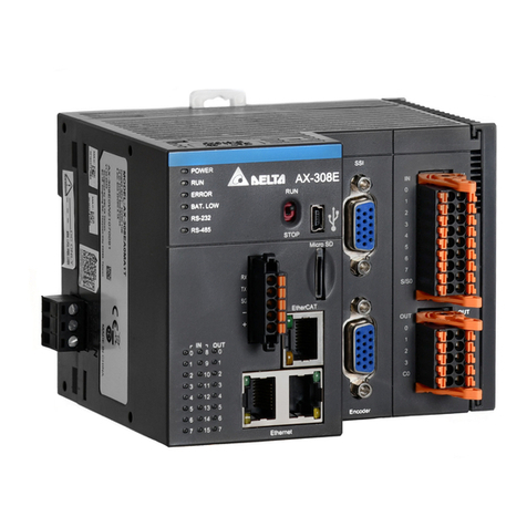
Delta AH500 series User manual


Chapter 1 Product Introduction
Table of Contents
1.1 Overview ...................................................................................................1-2
1.1.1 Related Manuals ................................................................................1-2
1.1.2 Model Description...............................................................................1-2
1.2 Characteristics...........................................................................................1-7
1-1

AH500 Hardware Manual
1.1 Overview
This manual introduces the programming of the AH500 series programmable logic controllers, the
basic instructions, and the applied instructions. This manual introduces the electrical specifications
for the AH500 series programmable logic controllers, the appearances, the dimensions, and etc.
1.1.1 Related Manuals
The related manuals of the AH500 series programmable logic controllers are composed of the
following.
zAH500 Quick Start
It guides users to use the system before they read the related manuals.
zAH500 Programming Manual
It introduces the programming of the AH500 series programmable logic controllers, the basic
instructions, and the applied instructions.
zISPSoft User Manual
It introduces the use of ISPSoft, the programming language (Ladder, IL, SFC, FBD, and ST),
the concept of POUs, and the concept of tasks.
zAH500 Hardware Manual
It introduces electrical specifications, appearances, dimensions, and etc.
zAH500 Operation Manual
It introduces functions of CPUs, devices, module tables, troubleshooting, and etc.
zAH500 Module Manual
It introduces the use of special I/O modules. For example, network modules, analog I/O
modules, temperature measurement modules, motion control modules, and etc.
zAH500 Motion Control Module Manual
It introduces the specifications for the motion control modules, the wiring, the instructions, and
the functions.
zPMSoft User Manual
It introduces the use of PMSoft, including the editing mode, the connection, and the password
setting.
1.1.2 Model Description
Classification Model Name Description
Power supply
module AHPS05-5A 100~240 V AC
50/60 Hz
AHCPU500-RS2 It is a basic CPU module with two built-in RS-485 ports, one
built-in USB port, and one built-in SD interface. It supports
768 inputs/outputs. The program capacity is 16 ksteps.
AHCPU500-EN
It is a basic CPU module with one built-in Ethernet port, one
built-in RS-485 port, one built-in USB port, and one built-in
SD interface. It supports 768 inputs/outputs. The program
capacity is 16 ksteps.
AHCPU510-RS2 It is a basic CPU module with two built-in RS-485 ports, one
built-in USB port, and one built-in SD interface. It supports
1280 inputs/outputs. The program capacity is 64 ksteps.
AHCPU510-EN
It is a basic CPU module with one built-in Ethernet port, one
built-in RS-485 port, one built-in USB port, and one built-in
SD interface. It supports 1280 inputs/outputs. The program
capacity is 64 ksteps.
CPU module
AHCPU520-RS2 It is a basic CPU module with two built-in RS-485 ports, one
built-in USB port, and one built-in SD interface. It supports
2304 inputs/outputs. The program capacity is 128 ksteps.
1-2

Chapter 1 Product Introduction
Classification Model Name Description
AHCPU520-EN
It is a basic CPU module with one built-in Ethernet port, one
built-in RS-485 port, one built-in USB port, and one built-in
SD interface. It supports 2304 inputs/outputs. The program
capacity is 128 ksteps.
AHCPU530-RS2 It is a basic CPU module with two built-in RS-485 ports, one
built-in USB port, and one built-in SD interface. It supports
4352 inputs/outputs. The program capacity is 256 ksteps.
CPU module
AHCPU530-EN
It is a basic CPU module with one built-in Ethernet port, one
built-in RS-485 port, one built-in USB port, and one built-in
SD interface. It supports 4352 inputs/outputs. The program
capacity is 256 ksteps.
AHBP04M1-5A Four-slot main backplane for a CPU /RTU rack
AHBP06M1-5A Six-slot main backplane for a CPU/RTU rack
AHBP08M1-5A Eight-slot main backplane for a CPU/RTU rack
Main
backplane
AHBP12M1-5A Twelve-slot main backplane for a CPU/RTU rack
AHBP06E1-5A Six-slot extension backplane for a CPU/RTU extension rack
Extension
backplane AHBP08E1-5A Eight-slot extension backplane for a CPU/RTU extension
rack
AH16AM10N-5A
24 V DC
5 mA
16 inputs
Terminal block
AH32AM10N-5B
24 V DC
5 mA
32 inputs
DB37 connector
AH64AM10N-5C
24 V DC
3.2 mA
64 inputs
Latch connector
AH16AM30N-5A
100~240 V AC
4.5 mA/9 mA (100 V and 50 Hz)
16 inputs
Terminal block
AH16AN01R-5A
240 V AC/24 V DC
2 A
16 outputs
Relay
Terminal block
AH16AN01T-5A
12~24 V DC
0.5 A
16 outputs
Sinking output
Terminal block
Digital
input/output
module
AH16AN01P-5A
12~24 V DC
0.5 A
16 outputs
Sourcing output
Terminal block
1-3

AH500 Hardware Manual
Classification Model Name Description
AH32AN02P-5B
12~24 V DC
0.1 A
32 outputs
Sinking output
DB37 connector
AH32AN02T-5B
12~24 V DC
0.1 A
32 outputs
Sourcing output
DB37 connector
AH64AN02T-5C
12~24 V DC
0.1 A
64 outputs
Sinking output
Latch connector
AH64AN02P-5C
12~24 V DC
0.1 A
64 outputs
Sourcing output
Latch connector
AH16AN01S-5A
110/220 V AC
0.5 A
16 outputs
TRIAC
Terminal block
AH16AP11R-5A
24 V DC
5 mA
8 inputs
240 V AC/24 V DC
2 A
8 outputs
Relay
Terminal block
AH16AP11P-5A
24 V DC
5 mA
8 inputs
12~24 V DC
0.5 A
8 outputs
Sinking output
Terminal block
Digital
input/output
module
AH16AP11T-5A
24 V DC
5 mA
8 inputs
12~24 V DC
0.5 A
8 outputs
Sourcing output
Terminal block
1-4

Chapter 1 Product Introduction
Classification Model Name Description
AH04AD-5A
Four-channel analog input module
16-bit resolution
0~10 V, 0/1~5 V, -5~+5 V, -10~+10 V, 0/4~20 mA, and
-20~+20 mA
Conversion time: 150 us/channel
AH08AD-5B
Eight-channel analog input module
16-bit resolution
0~10 V, 0/1~5 V, -5~+5 V, and -10~+10 V
Conversion time: 150 us/channel
AH04DA-5A
Four-channel analog output module
16-bit resolution
-10~10 V, and 0/4~20 mA
Conversion time: 150 us/channel
AH08DA-5B
Eight-channel analog output module
16-bit resolution
-10~+10V, 0~10V, -5~+5V, and 0/1~5V
Conversion time: 150 us/channel
Analog
input/output
module
AH06XA-5A
Four-channel analog input module
16-bit resolution
0~10 V, 0/1~5 V, -5~+5 V, -10~+10 V, 0/4~20 mA, and
-20~+20 mA
Conversion time: 150 us/channel
Two-channel analog output module
16-bit resolution
-10~10 V, and 0/4~20 mA
Conversion time: 150 us/channel
AH04PT-5A
Four-channel four-wire/three-wire RTD temperature sensor
Sensor type: Pt100/Pt1000/Ni100/Ni1000 sensor, and
0~300 Ωinput impedance
16-bit resolution: 0.1 ℃/0.1 ℉
Four-wire conversion time: 150 ms/channel
Three-wire conversion time: 300 ms/channel
AH04TC-5A
Four-channel thermocouple temperature sensor
Sensor type: J, K, R, S, T, E, N, and -150~+150 mV
24-bit resolution: 0.1 ℃/0.1 ℉
Conversion time: 200 ms/channel
Temperature
measurement
module
AH08TC-5A
Eight-channel thermocouple temperature sensor
Sensor type: J, K, R, S, T, E, N, and -150~+150 mV
24-bit resolution: 0.1 ℃/0.1℉
Conversion time: 200 ms/channel
AH02HC-5A Two-channel high-speed counter module
200 kHz
AH04HC-5A Four-channel high-speed counter module
200 kHz
AH05PM-5A Two-axis pulse train motion control module (1 MHz)
AH10PM-5A Six-axis pulse train motion control module
(Four axes: 1 MHz; Two axes: 200 kHz)
Motion control
module
AH20MC-5A Twelve-axis DMCNET (Delta Motion Control Network)
motion control module (10 Mbps)
1-5

AH500 Hardware Manual
Classification Model Name Description
AH10EN-5A It is an Ethernet master module with two built-in Ethernet
ports, and supports a Modbus TCP master.
AH10SCM-5A
It is a serial communication module with two
RS-485/RS-422 ports, and supports Modbus and the UD
link protocol.
There is isolation between two parts of communication, and
there is isolation between two parts of power.
Network
module
AH10DNET-5A It is a DeviceNet network module. It can function as a
master or a slave. The maximum communication speed is 1
Mbps.
RTU module AHRTU-DNET-5A RTU module for DeviceNet
AHACAB06-5A 0.6 meter extension cable for connecting an extension
backplane
AHACAB10-5A 1.0 meter extension cable for connecting an extension
backplane
AHACAB15-5A 1.5 meter extension cable for connecting an extension
backplane
Extension
cable
AHACAB30-5A 3.0 meter extension cable for connecting an extension
backplane
DVPACAB7A10 1.0 meter I/O extension cable (latch connector) for
AH64AM10N-5C
DVPACAB7B10 1.0 meter I/O extension cable (latch connector) for
AH64AN02T-5C and AH64AN02P-5C
DVPACAB7C10 1.0 meter I/O extension cable (DB37)
DVPACAB7D10 1.0 meter I/O extension cable for AH04HC-5A and
AH20MC-5A
I/O extension
cable
DVPACAB7E10 1.0 meter I/O extension cable (latch connector) for
AH10PM-5A
DVPAETB-ID32A I/O external terminal module forAH64AM10N-5C
32 inputs
DVPAETB-OR16A I/O external terminal module for AH64AN02T-5C
16 relay outputs
DVPAETB-OR16B I/O external terminal module forAH64AN02P-5C
16 relay outputs
DVPAETB-ID32B I/O external terminal module forAH32AM10N-5B
32 inputs
DVPAETB-OR32A I/O external terminal module for AH32AN02T-5B
32 relay outputs
DVPAETB-OR32B I/O external terminal module forAH32AN02P-5B
32 relay outputs
DVPAETB-OT32B I/O external terminal module forAH32AN02T-5B and
AH32AN02P-5B
32 relay outputs
DVPAETB-IO16C I/O external terminal module forAH04HC-5Aand
AH20MC-5A
External
terminal
module
DVPAETB-IO24C I/O external terminal module forAH10PM-5A
Space module AHASP01-5A Space module used for an empty I/O slot
1-6

Chapter 1 Product Introduction
1.2 Characteristics
AH500 system
The characteristics of theAH500 series CPU module are as follows.
(1) High efficiency
zThe AH500 series CPU module adopts a 32-bit high-speed processor. The instructions are
executed at a speed of 0.3 milliseconds per 1 ksteps. (Fifty percent of the instructions are
basic instructions, and fifty percent of the instructions are applied instructions.)
(2) Supporting more inputs and outputs
zThe AH500 series CPU module supports up to 4,352 local digital I/O or 512 analog I/O.
zA complete AH500 system consists of eight backplanes at most, including a main backplane.
Eight I/O modules at most can be installed on a backplane. Therefore, for the AH500 series
CPU, 64 digital input/output modules at most or 64 analog input/output modules at most can
be installed.
zEight RTU modules at most can be installed on the main backplane. 128,000 remote digital
I/O, or 4,000 remote analog I/O at most are supported.
(3) Multiple I/O modules
zThe I/O modules supported by theAH500 series CPU module are digital input/output
modules, analog input/output modules, temperature measurement modules, network
modules, motion control modules, and RTU modules.
Module Description
Digital
input/output
module
Digital input/output
AH16AM10N-5A, AH32AM10N-5B, AH64AM10N-5C, AH16AM30N-5A,
AH16AN01R-5A, AH16AN01T-5A, AH16AN01P-5A, AH32AN02T-5B,
AH32AN02P-5B, AH64AN02T-5C, AH64AN02P-5C, AH16AN01S-5A,
AH16AP11R-5A, AH16AP11T-5A, and AH16AP11P-5A
Analog
input/output
module
Analog input/output
AH04AD-5A, AH08AD-5B, AH04DA-5A, AH08DA-5B, and AH06XA-5A
1-7

AH500 Hardware Manual
Module Description
Temperature
measurement
module
Measuring the temperature
AH04PT-5A, AH04TC-5A, and AH08TC-5A
Motion
control
module
Controlling the motion
AH02HC-5A, AH04HC-5A, AH05PM-5A, AH10PM-5A, and AH20MC-5A
Network
module
Extending the communication interface (*There are multiple interfaces.All
network modules can be installed on the main backplane except
AH10SCM-5A.)
AH10EN-5A, AH10SCM-5A, and AH10DNET-5A
RTU module It is installed on the main backplane as a remote terminal unit. (*It
supports multiple communication interfaces.)
AHRTU-DNET-5A
(4) Larger program capacity and memory
zThe program capacity of the AH500 series CPU modules can be up to 256 ksteps. Users do
not need to use a more advanced CPU if the program capacity becomes large.
zThe AH500 series CPU module has 64 kwords of memory. Besides, users can declare up to
1024 function blocks.
(5) Supporting IEC 61131-3
zThe AH500 series CPU module supports IEC 61131-3.
1-8

Chapter 1 Product Introduction
zThe programming languages which are supported are instruction lists (IL), structured texts
(ST), ladder diagrams (LD), sequential function charts (SFC), and function block diagrams
(FBD).
zUsers can select a programming language according to their preference and the
convenience. The programming languages support one another so that the programs written
by different users are related.
(6) Strong function block
zNot only the standard IEC61131-3 function blocks are supported, but also the convenient
function blocks provided by Delta Electronics, Inc. are supported. Users can write the
program frequently executed in a function block so that the program becomes more
structured and can be executed more conveniently.
zThe symbol for a function block in a ladder diagram is like an Integrated circuit (IC) in a circuit
diagram. Owing to the fact that the ladder diagram is based on the traditional circuit diagram,
the operation of a function block is quite similar to the function of an integrated circuit. Users
only need to send the signal to the corresponding input of the function block, and they can
receive the signal or state which is required. During the whole process, users do not need to
consider the processing procedure inside the function block.
zA function block is a program element equipped with the operation function. It is similar to a
subroutine, and is a type of POU (Program Organization Unit). It can not operate by itself,
and has to be called through the program POU. After the related parameters are transmitted,
the function defined by a function block is executed. Besides, the final operation result can be
sent to the device or variable used in the superior POU after the execution of the function
block is complete.
zThe encryption function supported by ISPSoft provides the secrecy of function blocks for
special businesses. The program inside a function block can not be learned, and the patent
of a business will not be infringed.
1-9

AH500 Hardware Manual
(7) Task
zThe programs can be assigned to 283 tasks at most.Among the 288 tasks, 32 tasks are
cyclic tasks, 32 tasks are I/O interrupts, 4 tasks are timed interrupts, 2 tasks are
communication interrupts, 1 task is an external 24 V low-voltage interrupt, and 212 tasks are
user-defined tasks.
zUsers can enable and disable a task during the execution of a program by means of TKON
and TKOFF.
(8) Increasing the efficiency of configuring the hardware through an USB cable and ISPSoft
zThe AH500 series CPU module provides a standard USB 2.0 interface. USB 2.0 increases
the data transfer rate, and decreases the time it takes to download the program, monitor the
program and configure the hardware. Besides, users do not need to buy a communication
cable for the CPU module. They can use a general USB cable to connect to theAH500 series
CPU module.
(9) Serial control interface with multiple functions
CPU530-RS2
RUN
ERROR
BUS FAULT
SYSTEM
COM1
COM2
C
O
M
C
O
M
2
1
USB
CPU530-EN
RUN
ERROR
BUS FAULT
SYSTEM
COM
Ethernet
COM
USB
zAHCPU500/510/520/530-RS2 provides two DB9 serial control interfaces, i.e. COM1 and
COM2.
zAHCPU500/510/520/530-EN provides one DB9 serial control interface, i.e. COM.
1-10

Chapter 1 Product Introduction
zUsers can set the DB9 serial control interface to RS232, RS485, or RS422 according to the
application environment. The data transfer rate can be increased from 9600 bps to 1 Mbps.
zAfter users set the PLC Link in ISPSoft, they can exchange the data with a device on the
RS-485 network through the RS-485 serial control interface, and do not need to write any
program.
(10) High-speed Ethernet communication interface
zAHCPU500/510/520/530-EN is equipped with a 10/100 M Ethernet communication interface,
and supports emails, webs, and socket services.
zAfter users set the Ether Link in ISPSoft, they can exchange the data with a device in the
Ethernet network through the Ethernet communication interface, and do not need to write any
program.
zThe status or the error message related to the system is sent to users’ email boxes
immediately. Users do not need to be on the spot to understand the problem.
(11) Memory card
zThe memory card has the following functions.
System backup: The user program, the CPU parameters, the module table, the setting value
in the device
System recovery: The user program, the CPU parameters, the module table, and the setting
value in the device
Parameter storage: The value in the device
Log storage: The system error log and the system status log
(12) Hot swap
zThe AH500 series I/O modules support the on-line uninterruptible hot swap. When the
system runs, users can replace the module which breaks down without disconnecting the
module. After the module is replaced, the new module runs normally. Users do not need to
set the module manually or switch the state.
(13) Supporting the on-line debugging mode
zAfter a single instruction step has been complete, or after a breakpoint is specified, users can
easily find the bug in the program by means of the on-line debugging mode supported by the
AH500 series CPU module.
zIf users want to enter the debugging mode, the CPU module must run.After users enable the
on-line monitoring function, they have to click . The debugging screen varies from
programming language to programming language, but the same operation applies to these
programming languages. For theAH500 series PLC, structured texts do not support the
debugging mode, and sequential function charts support the debugging mode during the
action and the transition.
1-11

AH500 Hardware Manual
Step 1: Setting the PLC to RUN
Step 2: Entering the on-line mode
1-12

Chapter 1 Product Introduction
Step 3: Entering the debugging mode
(14) Supporting the on-line editing mode
zWhen the system runs, users can make use of the on-line editing mode to update the
program without affecting the operation of the system.
zWhen the system is in the on-line monitoring mode, users can enter the on-line editing mode
by clicking .
1-13

AH500 Hardware Manual
zAfter the program is modified and compiled, users can update the program in the CPU
module by clicking .
1-14

Chapter 2 Installing the Hardware
Table of Contents
2.1 AH500 Hardware Framework....................................................................2-2
2.1.1 Component Parts of the AH500 Hardware.........................................2-2
2.1.1.1 Necessary Components..............................................................2-2
2.1.1.2 Accessories.................................................................................2-4
2.1.2 Installing Modules on a Main Backplane............................................2-7
2.1.3 Installing Modules on an Extension backplane...................................2-8
2.1.4 Connecting a Main Backplane to an Extension Backplane ................2-8
2.2 Warning.....................................................................................................2-9
2.3 Installation.................................................................................................2-9
2.3.1 Installation of Modules in a Control Box.............................................2-9
2.3.2 Mounting a Backplane........................................................................2-9
2.3.3 Installing a Module ...........................................................................2-12
2.3.4 Installing a Removable Terminal Block.............................................2-13
2.3.5 Installing a Wiring Module................................................................2-14
2.3.6 Connecting Backplanes....................................................................2-15
2.3.7 Putting a Communication Cable.......................................................2-16
2-1

AH500 Hardware Manual
2.1 AH500 Hardware Framework
2.1.1 Component Parts of the AH500 Hardware
A complete AH500 system consists of a main backplane, extension backplanes, power supply
modules, a CPU module, I/O modules, and extension cables. The basic AH500 system is illustrated
below.
7backplanes
.
.
.
.
.
.
2.1.1.1 Necessary Components
A complete AH500 system consists of the following four necessary components.
zMain backplane
A CPU module and other modules are installed on a main backplane which provides the function
of connecting buses. The main backplanes are divided into four types according to the number of
I/O modules installed on the main backplanes. These four types are four-slot main backplanes,
six-slot main backplanes, eight-slot main backplanes, and twelve-slot main backplanes. Besides,
a CPU module installed on a main backplane can be replaced by a RTU module on a control
network. Please notice that there is at least one CPU module on a control network.
POWER CPU I/O0 I/O1 I/O2 I/O3 I/O4 I/O5 I/O6 I/O7
2-2

Chapter 2 Installing the Hardware
zPower supply module
A power supply module functions to convert alternating current to direct current, and provides
power for the modules installed on it. A power supply module has to be installed on the left-most
side of a backplane.
PS05
POWER
zCPU module
A CPU module is the nucleus of a complete AH500 system. It is responsible for controlling and
managing the whole system, and is installed in the second slot from the left on the main
backplane. Besides, Delta Electronics, Inc. provides businesses with several types of CPU
modules. Users can select a CPU module according to their needs.
CPU530-RS2
RUN
ERROR
BUS FAULT
SYSTEM
COM1
COM2
C
O
M
C
O
M
2
1
USB
CPU530-EN
RUN
ERROR
BU S FAULT
SYSTEM
COM
Ethernet
COM
USB
zCommunication cable
Several communication interfaces are built in a CPU module, and users are provided with many
types of network modules. Users can select a suitable Communication cable according to the
actual situation.
Please refer to the following table for information about the communication interfaces and the
main applications. The specifications for the interface on an extension backplane are defined by
Delta Electronics, Inc. itself. The interface is used to connect the backplanes, and users need to
use a Delta extension cable.
2-3

AH500 Hardware Manual
Interface Connector Application
Communication
port DB9 Computer/HMI communication/Industrial control network
(RS-232/422/485)
Ethernet RJ45
Computer/HMI communication/Remote control/Data
exchange/Industrial control network
USB Mini USB Computer communication
DeviceNet DeviceNet
Industrial control network
The maximum data transmission rate is 1 Mbps.
Interface on an
extension
backplane
Delta
connector Extension cable for a complete AH500 system
2.1.1.2 Accessories
The following are the accessories for anAH500 system. Users can select them according to their
needs.
zExtension module
Apart from the standard communication ports on a CPU module, the CPU module does not
equipped with other I/O functions. If users want to use I/O functions, they can select suitable
modules according to the actual situation. The modules which can be used with an AH500
system are listed in the table below.
The digital input/output modules:
AH16AM10N-5A
24 V DC
5 mA
16 inputs
Terminal block
AH32AM10N-5B
24 V DC
5 mA
32 inputs
DB37 connector
AH64AM10N-5C
24 V DC
3.2 mA
64 inputs
Latch connector
AH16AM30N-5A
100~240 V AC
4.5 mA/9 mA (100 V, 50 Hz)
16 inputs
Terminal block
AH16AN01R-5A
240 V AC/24 V DC
2 A
16 outputs
Relay
Terminal block
AH16AN01T-5A
12~24 V DC
0.5 A
16 outputs
Sinking output
Terminal block
2-4

Chapter 2 Installing the Hardware
AH16AN01P-5A
12~24 V DC
0.5 A
16 outputs
Sourcing output
Terminal block
AH16AN01S-5A
110/220 V AC
0.5 A
16 outputs
TRIAC
Terminal block
AH32AN02T-5B
12~24 V DC
0.1 A
32 outputs
Sourcing output
DB37 connector
AH32AN02P-5B
12~24 V DC
0.1 A
32 outputs
Sinking output
DB37 connector
AH64AN02T-5C
12~24 V DC
0.1 A
64 outputs
Sinking output
Latch connector
AH64AN02P-5C
12~24 V DC
0.1 A
64 outputs
Sourcing output
Latch connector
AH16AP11R-5A
24 V DC
5 mA
8 inputs
240 V AC/24 V DC
2 A
8 outputs
Relay
Terminal block
AH16AP11T-5A
24 V DC
5 mA
8 inputs
12~24 V DC
0.5 A
8 outputs
Sourcing output
Terminal block
2-5
Other manuals for AH500 series
4
This manual suits for next models
47
Table of contents
Other Delta Computer Hardware manuals

Delta
Delta M125HV-113 User manual

Delta
Delta PMC-24V075W1AA User manual

Delta
Delta CMM-EC02 User manual

Delta
Delta AX-3 Series User manual

Delta
Delta CoolDoor User manual

Delta
Delta DVP-FEN01 User manual

Delta
Delta CMM-DN01 User manual

Delta
Delta PMC-DSPV100W1A User manual

Delta
Delta EtherCAT CMM-EC03 User manual

Delta
Delta 06A2 User manual