Delta CoolDoor User manual

Delta InfraSuite Precision Cooling
The power behind competitiveness
www.deltapowersolutions.com
CoolDoor
User Manual

InfraSuite - CoolDoor
2
SAVE THIS MANUAL
This manual contains important instructions and warnings that you should follow during
the installation, operation, storage and maintenance of this product. Failure to heed these
instructions and warnings will void the warranty.
Copyright © 2021 by Delta Electronics Inc. All Rights Reserved. All rights of this User Manual
(“Manual”), including but not limited to the contents, information, and figures are solely
owned and reserved by Delta Electronics Inc. (“Delta”). The Manual can only be applied to
the operation or the use of this product. Any disposition, duplication, dissemination,
reproduction, modification, translation, extraction, or usage of this Manual in whole or in part
is prohibited without the prior written permission of Delta. Given that Delta will continuously
improve and develop the product, changes may be made to the information in this Manual
at any time without obligation to notify any person of such revision or changes. Delta will
make all possible efforts to secure the accuracy and the integrity of this Manual. Delta
disclaims any kinds or forms of warranty, guarantee, or undertaking, either expressly or
implicitly, including but not limited to the completeness, faultlessness, accuracy, non-
infringement, merchantability or fitness for a particular purpose of the Manual.

3
Table of Contents
Chapter 1 : Guide for Safe Operation....................................................................................5
1.1 Safety Instructions ..................................................................................................5
1.1.1 Installation Instructions ................................................................................6
1.1.2 Instructions for Use ......................................................................................6
1.2 Nameplate Information............................................................................................7
1.3 Product Introduction ................................................................................................8
1.4 Functions & Features ..............................................................................................8
1.5 Dimensions ...........................................................................................................10
1.6 Design Capacities .................................................................................................11
Chapter 2 : Introduction .......................................................................................................12
2.1 Packing List...........................................................................................................12
2.2 Optional Accessories ............................................................................................14
2.3 Appearance...........................................................................................................14
2.4 Component Identification ......................................................................................15
2.5 Piping System .......................................................................................................17
Chapter 3 : Installation.........................................................................................................18
3.1 Installation Site......................................................................................................18
3.2 Space Reservation................................................................................................19
3.3 Handling ................................................................................................................20
3.4 Positioning.............................................................................................................21
3.4.1 Remove the Rack Door Panel ...................................................................21
3.4.2 Install CoolDoor Connect Duct ..................................................................22
3.4.3 Hang CoolDoor on Connect Duct ..............................................................23
3.5 Holing ....................................................................................................................24
3.6 Piping Installation Size..........................................................................................25
3.7 External Piping ......................................................................................................26
3.8 CoolDoor Water Side Installation Components ....................................................27
3.8.1 CoolDoor Control Ball Valve (Standard Accessory)...................................27
3.8.2 Pressure Independent Control Valve (Optional Accessory).......................29
3.8.3 Leakage Cut Off Valve (Optional Accessory).............................................30
3.8.4 Flow Meter (Optional Accessory)...............................................................31
InfraSuite - CoolDoor
4
3.9 Remote Sensor (Optional Accessory)...................................................................32
3.10 Water Leakage Detection Sensor (Standard Accessory) .....................................32
3.11 Water Quality Requirements .................................................................................34
Chapter 4 : Wiring................................................................................................................35
4.1 Connect the Power Cables ...................................................................................35
4.2 Connect the Signal Cables ...................................................................................36
4.3 Panel Diagram ......................................................................................................39
Chapter 5 : Initial Start-up....................................................................................................45
5.1 Inspection Prior to Activation.................................................................................45
5.2 Operating Temperature & Humidity.......................................................................46
5.3 Power Supply ........................................................................................................48
5.4 Ventilation..............................................................................................................48
5.5 Water Volume Equilibrium.....................................................................................50
Chapter 6 : Operation ..........................................................................................................51
6.1 Menu Tree .............................................................................................................51
6.2 Control Panel ........................................................................................................52
6.3 Status Page Operation..........................................................................................53
6.4 Account Access Authorization & Log-in ................................................................62
6.5 Turbo Boost...........................................................................................................62
Chapter 7 : Fault Code & Descriptions ................................................................................65
7.1 Troubleshooting ....................................................................................................65
7.2 Warning Codes .....................................................................................................67
Chapter 8 : Maintenance & Cleaning...................................................................................73
8.1 Component Maintenance......................................................................................73
8.2 Component Replacement .....................................................................................74
8.3 Quarterly Maintenance..........................................................................................76
Chapter 9 : MODBUS Table.................................................................................................78
Appendix 1 : Specifications .................................................................................................80
Appendix 2 : Warranty .........................................................................................................82

5
Chapter 1 : Guide for Safe Operation
1.1 Safety Instructions
•Carefully read all chapters of the Manual before any installation, operation, or
maintenance. To avoid personal injury and equipment damage, be sure to operate the
product in accordance with the instructions in this Manual and the markings on the
cabinet.
•The system has various hazards, including machinery, electrical appliances, sound,
vibration and other hazards. Therefore, this must be performed by qualified
professional operators, installation personnel and maintenance personnel who have
received trained. This equipment has the following hazards:
Electric shock
High pressure water stream
Pinching in rotating components
Cuts from the heatsink
Crushing or falling-over from structural weight
•The unit should only be moved by at least two people so as to guarantee safety.
•In handling or removal of the equipment, pay attention to its height and center of gravity.
When using transport equipment for handling, it must be raised from the bottom to
avoid toppling.
•The unit contains moving components. Be careful to keep it away from arms, legs, hair,
clothes and jewelry, so as to avoid any danger.
•When the CoolDoor, which has a certain weight, is installed in an empty rack, the
counterweight in the rack should be appropriately increased to avoid tipping due to
unstable center of gravity.

InfraSuite - CoolDoor
6
1.1.1 Installation Instructions
•Installation and operation should comply with local regulations. Installation
professionals must have certification in accordance with national regulations. And the
safety and health of personnel must be ensured at all times during the installation and
removal processes.
•The unit can be connected to a single or dual power source. Make sure the input power
is disconnected before making a connection. If necessary, use a multi-meter to confirm
this.
•Do not install the equipment on a flammable or unstable floor.
•This unit is only intended for indoor use. The indoor environment must be separated
from the outside air so as to avoid temperature and humidity interference. Consult
national or local regulations for separating the installation environment.
•The diameters and lengths of all electronic connection wires must follow the
requirements of the International IEC or relevant national regulations, whichever is
stricter. Meanwhile, the grounding wires of the unit must be effectively connected with
the grounding system.
1.1.2 Instructions for Use
•The inner high voltage of the unit may be fatal! The inner components may have hidden
dangers and only qualified service personnel can operate the unit. Improper operation
may lead to serious injury or death or equipment damage. Be sure to follow all the
instructions and warnings contained in the Manual.
•When the person leaves, make sure there are no foreign objects in the cabinet.
WARNING:
This device is powered by high voltage! May cause severe injury or death. Power
supplied to the equipment must be isolated by an electrical cutoff device. Any and
all electrical connections or procedures may only be performed by a certified
electrician. All electrical work or procedures must comply with local, state, and
national electrical standards and regulations. Except for the power supply, do not
make any other electrical connections with this device.

7
1.2 Nameplate Information
Model Name
Puduct : Rear Door Cooling
Model No. : RWC050D0AK00B8
Unit Name : Cool Door 50kW
Power Supply : 1~ 200-240Vac Max 4.2A 50/60Hz
MCA : 4.5A
MOP : 5.5A
Fan Motor , FLA/HP(Q'ty) : 0.9A / 0.242HP(4)
Rated Air Volume (Ref.) : 4016 CFM (113.7 CMM)
Max Allowable Inlet Pressure :
142 psig (10 kg/cm2)
Net Weight : 216 lb (98 kg)
Made in : Taiwan
Customer code
Product version
Filter option/reserve code
Application auxiliary selection/installation method
Function option/application environment
Model options
Supplementary option/reserve code
Series name/system name
Product capacity
Product category

InfraSuite - CoolDoor
8
1.3 Product Introduction
The CoolDoor precision cooling device (chilled water type) is an air conditioning product that
must be installed in combination with an IT rack or any standard rack, and is capable of
quickly removing and outputting hot air from the racks. It can achieve precise control through
the internal heat exchanger, EC fan, chilled water ball valve, and PLC control. On the outer
frame, the side cover can be removed for parallel installation, so that the hot aisle can be
shared to achieve the effect of mutual backup. For the installation of the chilled water
pipeline, you can choose the cross-over joint or quick joint; the method of matching to the
soft tubes is closer to the user's installation method. Because this product is used in direct
combination with the rack, it goes beyond the traditional hot and cold aisle installation
method, allowing the data center to be more compact with a high-density heat dissipation
method.
1.4 Functions & Features
•Intelligent control
The built-in MCU accurately detects and balances the data center’s heating load
change, automatically adjusting the CoolDoor’s chilled water flow and air flow to meet
the temperature control target.
•User-friendly control interface
Easy setting and monitoring and access to system status.
•Two-way ball valve
Provides proper flow of chilled water to dissipate heat. When the power supply is in an
emergency shutdown state, the valve spring is reset to the closed state to avoid
continuous supply of ice water when it is ineffective.
•Electronically commutated fan
The unit is equipped with high efficiency EC fans; the fan speed is adjustable from 30
to 100% for more energy saving.
•Alarm system
The fire smoke sensor can use the input dry contact to execute an alarm; it can be
emergency shut down according to customer needs. And it can alert users through
MODBUS RTU.

9
•Hot aisle expansion
Disassembly and installation can be performed through the side panels of the
CoolDoor to achieve sharing of the hot aisle and partial backup for adjacent CoolDoor-
Rack systems.
•Lockable access door
The CoolDoor includes a locking mechanism to prevent unrelated personnel from
opening it. The access door is located in the front, which facilitates professionals
performing maintenance.
•Built-in ATS
When there is a main Feed A fault, this will transfer to Feed B, to keep the unit working
normally.
•Water Leakage detection
Uses a 4m water leakage detector, which will immediately inform the user of any water
leakage so as to protect the safety of the equipment. And optional Cut off valve to cut
off the water inlet and outlet to avoid the expansion of water leakage.
•Remote control
Remote control via the input dry contact.
•Turbo boost control
Built on the hot aisle expansion function, adjacent CoolDoors can be used to recover
when there are ball valve abnormalities, fan abnormalities, and severe abnormalities
to reduce hazard to the rack.

InfraSuite - CoolDoor
10
1.5 Dimensions
Model no.
H
W
W2
D
D1
S1
RWC050D0AK00B8
1968 mm
660.4mm
373mm
374.5mm
176mm
355mm
T1
T2
T3
B1
B2
S2
160mm
143mm
22mm
160mm
158mm
80mm
T1
T2
B2
B1
W2
W
D
D1
S1
S2
H

11
1.6 Design Capacities
The range of design conditions shown in the above table will vary with the user's design
ability, water volume, and different return air temperatures. It is recommended that you
contact Delta service personnel and provide them with detailed calculation parameters in
the design.
CoolDoor
Unit
Quantity
Duct connection
Rack Unit Height
U
42U‐48U
Rack Unit Width
mm
600-800mm
Rack Unit Deep
Inch
12
Water Side
Fluid Type
Water or Glycol
Fluid Flow
GPM
<23.8
Pressure Drop (coil + ball valve)
Psi
9.4
Inlet Temperature
°F
53.6~68
Cooling Capacity
kW
<53
Max Allowable Inlet Pressure
Psig
142
Air Side
Air Volume
CFM
2000~4016
Cabinet
Approximate Shipping Weight
Lbs
367-385
Approximate Operating Weight
Lbs
198-216
Electricity
Power Supply
200-240V / 1N / 50,60Hz
MCA
A
4.5
MOP
A
5.5

InfraSuite - CoolDoor
12
Chapter 2 : Introduction
2.1 Packing List
1
2
5
3
6
4
7
8

13
No.
Description
Quantity
Standard Part
1
CoolDoor Cooling Unit
1
V
2
User Manual
1
V
3
Door Key
2
V
4
Ball Valve Body
1
V
5
Ball Valve Actuator
1
V
6
Pressure Independent Control Valve
1
7
Electric Shut-off Valve
1
8
Remote Sensor
1

InfraSuite - CoolDoor
14
2.2 Optional Accessories
If you need to purchase the following accessories, please contact service personnel.
•SNMP card: Used with Delta SNMP card to provide the best compatibility.
•Remote temperature and humidity sensor: It can monitor the environmental dew
point temperature and reduce the risk of condensation through the CoolDoor control.
•Quick joint: Easy and fast hose pipe replacement.
•Pressure independent control valve: The water volume can be balanced without
going through a balancing valve.
•Cut off valve: Can block the waterway when the system leaks.
•Flow meter: Can monitor the flow of the CoolDoor, and can be used for TAB
adjustment.
2.3 Appearance
(Figure 2-1: Outer Dimensions)

15
2.4 Component Identification
External
(Figure 2-2: External View)
No.
Description
No.
Description
1
Display Panel
7
Upper Signal Cable Inlet
2
Connect Duct
8
Rear Door
3
Handle
9
Control Panel Cover
4
Hot Aisle Cover
10
Bottom Signal Cable Inlet
5
Upper Water Pipe Inlet
11
Bottom Water Pipe Inlet
6
Power Cable Inlet
12
Status LED

InfraSuite - CoolDoor
16
Internal
(Figure 2-3: Internal View)
No.
Description
No.
Description
1
Fan
6
Outlet Pipe
2
Control Panel
7
Inlet Pipe
3
Supply Air Temperature Sensor
8
Return Air Temperature Sensor
4
Air Pressure Detector
9
Coil Protector
5
Electronic Panel
10
Coil

17
2.5 Piping System
(Figure 2-4: Piping System)
No.
Description
No.
Description
1
Lower inlet connector
5
Inlet water temperature sensor
2
Lower outlet connector
6
Outlet water temperature sensor
3
Upper inlet connector
7
Coil
4
Upper outlet connector
8
Air Vent

InfraSuite - CoolDoor
18
Chapter 3 : Installation
WARNING:
1. Only service personnel can perform the following installation procedures. No
installation, piping or handling should be performed without authorization, so
as to avoid equipment damage and personal injury.
2. The high voltage in the equipment is potentially fatal! The inner components
have potential dangers and only qualified service personnel can perform
wiring.
3.1 Installation Site
When planning the installation site for the cooling unit, you must take the following into
consideration so as to guarantee the best efficiency.
•Environmental requirements: The installation site must allow for moving the
equipment into and out of the site; the flooring must bear the weight of the equipment;
and there must be a sufficient space for maintenance, operation, and pipe repair. The
cooling unit can only be located indoors, and the indoor environment must be isolated
from the outside air to avoid temperature and humidity interference. The outside
humidity entry must be minimized in accordance with the local or national regulations
so as to avoid the increase of operation costs due to loss of cooling capacity.
•Humidity and heat source: Implement water-proofing and heat insulation engineering
for the indoor environment so as to isolate the outside humid hot air.
NOTE:
The unit cannot humidify or automatically de-humidify. If the humidity of the
installation environment exceeds the operation scope (refer to 5.2 Operating
Temperature & Humidity), the condensation of the water on the coil and pipes
may lead to trigger an alarm.
•Noise impact: At a high load, the operation of this cooling unit may produce loud noise.
Therefore, it is not suitable to install the unit close to offices.
•Input power: In connecting the power supply, make sure that the power conforms to
the rated value, and that the power distribution device is sufficient to satisfy the load
requirement. Inspect the rated values of each unit and make sure they have been
properly grounded. One branch circuit or power distribution device can only be
connected with one cooling unit.

19
3.2 Space Reservation
To facilitate maintenance and operation, and to promote air flow circulation, leave clearance
in the equipment's surroundings.
1. To ensure normal operation of the indoor unit, whenever possible, select a spacious
room to install the indoor unit in. It is advised to leave at least 2.5 feet on the rear where
the door opens to facilitate wiring and piping, as is shown in Figure 3-1.
If lower piping is adopted, the height of the elevation stand may not be less than 2 feet.
2. Avoid placing the indoor unit in a narrow place; otherwise, it will obstruct air flow and
shorten the cooling cycle, resulting in air return short circuit and air noise.
3. Avoid placing the indoor unit in a dead end or at the end of a narrow and long space.
4. To facilitate daily care and maintenance, do not install other equipment in the airway
above the air handling unit.
(Figure 3-1: Clearance Area)
(Figure 3-2: Under Floor Piping)

InfraSuite - CoolDoor
20
3.3 Handling
Transport
Before relocating this equipment to the installation site, follow the precautions below and
plan the transport route:
1. Make sure that the passageway, floor, elevator, or ramp along the transport route can
withstand the weight of this equipment and the transport equipment, and clear the
passageway in order to avoid collision.
2. In case of a slope along the transport route, the incline may not be greater than 15
degrees, in order to avoid toppling of the cabinet.
3. When relocating the cabinet over a long distance, use transportation equipment such as
the forklift in Figure 3-3 or the hoist in Figure 3-4).
4. When relocating this equipment, mind the height of the center of gravity. Transport
requires at least two people at the same time, in order to ensure safety.
(Figure 3-3: Transport with A Forklift)
(Figure 3-4: Transport with A Hoist)
This manual suits for next models
1
Table of contents
Other Delta Computer Hardware manuals

Delta
Delta EtherCAT CMM-EC03 User manual

Delta
Delta CMM-EC02 User manual

Delta
Delta DVP-FEN01 User manual

Delta
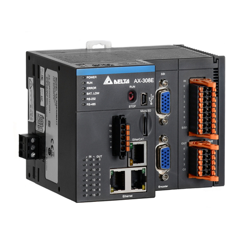
Delta AX-3 Series User manual

Delta
Delta PCI-DMC-F01 User manual

Delta
Delta AH500 series User manual

Delta
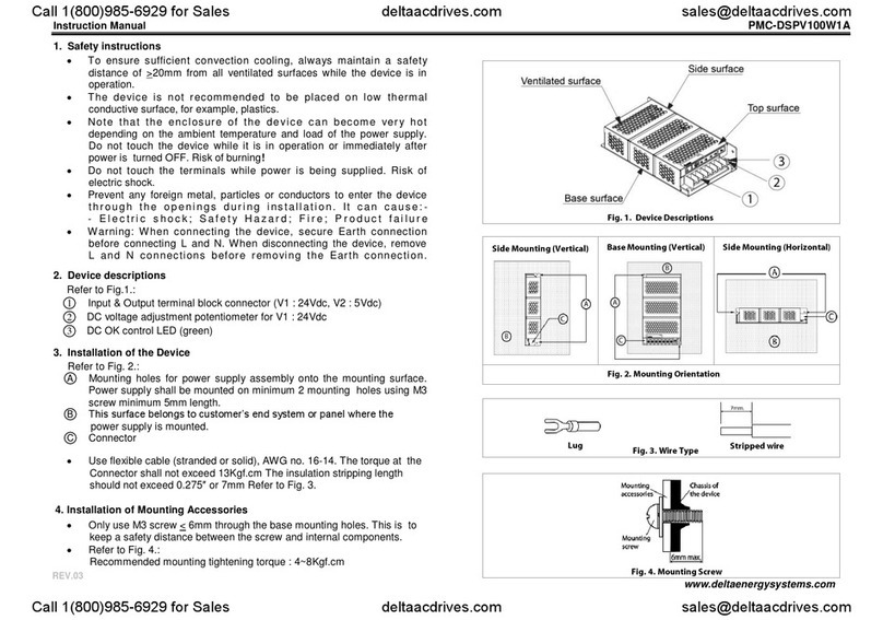
Delta PMC-DSPV100W1A User manual

Delta
Delta PMC-24V075W1AA User manual

Delta
Delta CMM-DN01 User manual

Delta
Delta 06A2 User manual
Popular Computer Hardware manuals by other brands

SMSC
SMSC LPC47M997 Specifications

Huawei
Huawei MPUA Specifications

Delta Electronics
Delta Electronics Suppression Inductors LFZ24V Specification sheet

Intel
Intel BX80623I72600K manual

Matrox
Matrox RadientPro CL Installation and Hardware Reference

Texas Instruments
Texas Instruments TPA6138A2 EVM user guide