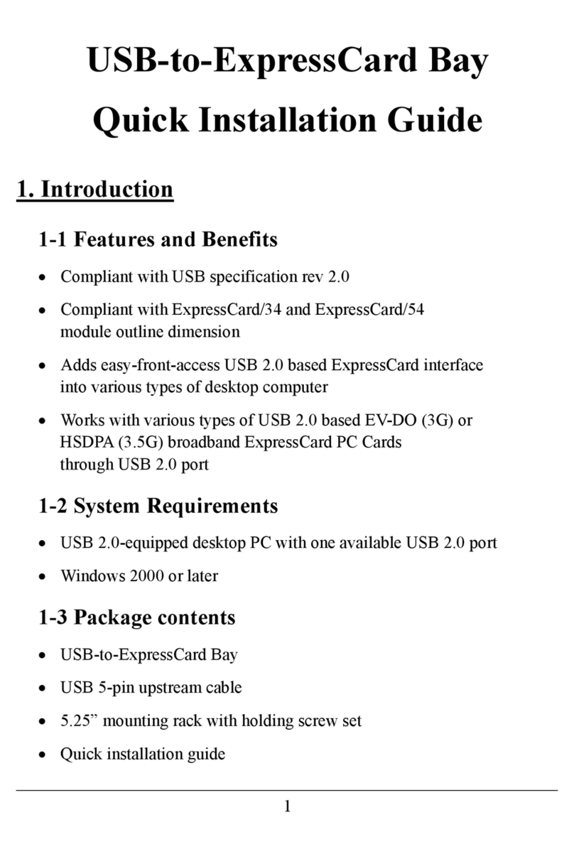
Quick Installation Guide
DC Wiring Box for M125HV_113
For more instruction and specification, please scan QR-code to see user manual.
> Inverter > M125HV_113 Operation and Installation Manual
M125HV_113 user manual
https://mydeltasolar.deltaww.com/?p=product_manual
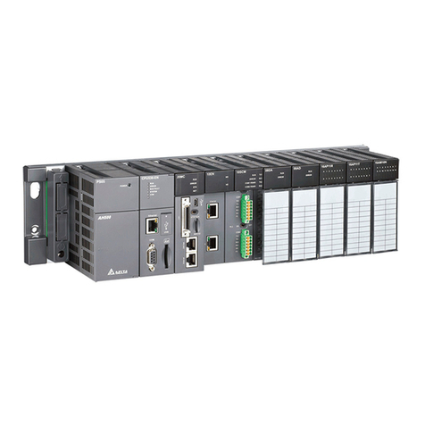
Descriptions of Components
Layout
Electrical Installation for DC Wiring
Installation Steps
Description
1 For DC cable wiring
5 For DC cable wiring
2The Instruction to provide the information of safety,
Installation and specification.
3 To fix DC wiring box at the bottom of the inverter
4
Object
DC Wiring Box
M12 Hex Nut and Washer
Quick Installation Guide
M5 Hex Nut
M8 Hex Nut
Qty
1
1
5
3 set
3 To fix DC cable from M125HV inverter
1
2
3
4
ComponentNO.
DC terminal
28.9 mm gland for DC Wiring
DC switch
Fuse holder
① ③ ④ ⑤
x3
②
Wall
Step 1Step 2Step 3
Wall
Mount the inverter Install the DC wiring box Start DC & AC cabling
Wall
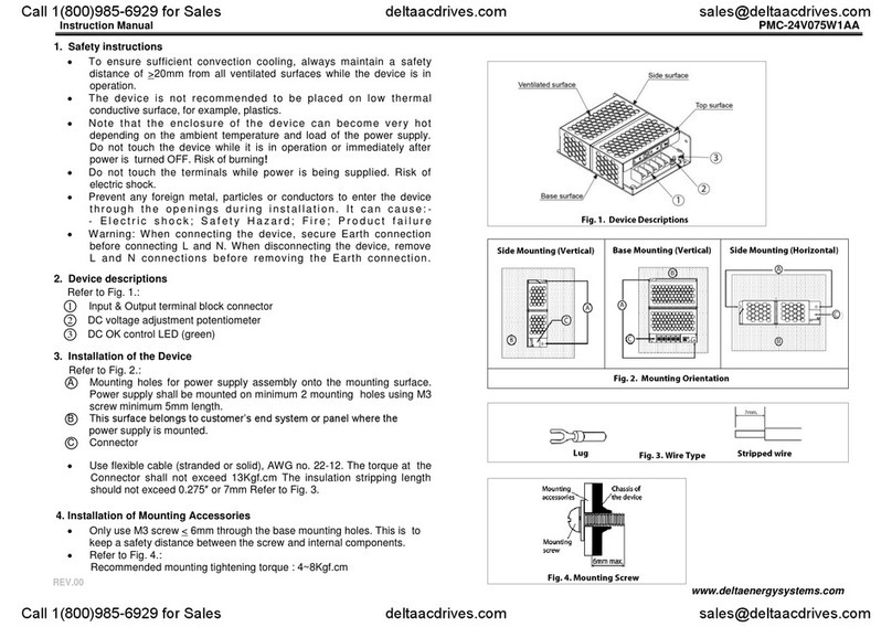
After mounting M125HV, please open the front cover of the DC wiring box before
install the wiring box on the inverter.
Pass through the DC cable from M125HV to DC wiring box, Use 4 M5 hex nut to fix the DC wiring box on the
M125HV inverter. (M5 Nut torque: 3.0 N•m)
* Screw torque: 4.4 N•m
Use M8 hex nut to tighten the cable on terminal.
* M8 Nut torque: 14.7 N•m
PV+
PV
-
outer
jacket
Conductor cross-section:
Cu: 50 ~ 300 mm2
Al: 120 ~ 300 mm2
Below is the procedure for preparing the DC conductors for connection to the DC terminals:
• It is important to choose the proper size for DC cable.
• The cross-sectional area for each DC conductor is 50~300 mm2for Cu. (120~300 mm2for Al)
• The maximum width of each terminal lugs should be within 34 mm, the diameter of screw hole should be
larger than Φ12.5 mm.
• Terminal can use for Cu lug (Tin plated).
5013294300
② ③ ④
①
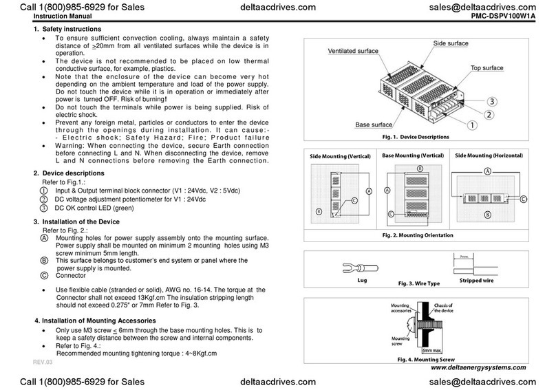
DC wiring box Installation
DC terminal
After inserting conductor,
torque terminal nut by 45 N•m
Bottom DC entry
Up to 28.9 mm trade size gland
The thread surface of
the washer must contact
to hex nut.
PV
-
PV+
Prior to installing conductors on terminal complete the following procedure to make terminals ready for connections.
For each of the DC terminals (PV+ / PV-):
Tighten/Lose nuts with 19 mm socket. If an electric socket is utilized insure the torque setting is low enough to
NOT OVER-TORQUE the screw. Once nut bottoms out, do not turn it any further.
Extreme temperature rise at the clamping point
If the contact resistance between the aluminum conductor and clamping point is toohigh, the
clamping point can become very hot and even catch fire in extreme cases.
To ensure a safe and reliable contact, always perform the following work steps:
Please select the Al wire size according to rules due to lower conductivity of Al.
Keep the installation location as free as possible from moisture or corrosive atmospheres.
Connect the aluminum cables quickly.
Tighten the clamping screw in the clamping body with the maximum permissible tightening torque.
NOTICE
The figure above illustrates the location of the DC conduit entry and connections to the DC terminal block:
- Ensure the correct conductor is connected to the appropriate terminal.
- After conductor is inserted, use M12 nuts to tight PV+/PV- terminal with a torque of 45 N•m.
DANGER : ELECTRICAL HAZARD!!
- PV array converts sunlight into electric power with high DC voltage and high DC current which can cause
dangerous electrical shock hazard!
- Use an opaque material to cover the PV array before wiring or cabling.
- Ensure the correct polarities are connected when DC cabling is applied.
DANGER!
- It is forbidden to open both doors at the same time.
WARNING !
- The risk of electric shock and fire exists because of high DC and AC voltages.
- Only PV modules that are listed with system voltage under 1600V are permitted for use.
- Inverter warranty void if the DC input voltage exceeds 1600 Vdc.
- Ensure the DC switch is placed in the "OFF" position, and the PV array is disconnected when doing DC cabling.
CAUTION: DC SWITCH ON/OFF !
- In order not to damage the components in the inverter, don’t repeat to change the status of DC Switch quickly,
the correct operation is waiting for the LED display show "green off and yellow flash" (No DC) or turn on the
switch after 5 minutes later.
CAUTION: WRONG AC WIRING !
- In order not to damage the components in the inverter, ensure the correct conductor is connected to the
appropriate DC terminal on the inverter.
- Ensure the DC conductors used are sized to the correct ampacity per NEC or other local code.
<34 mm
<32 mm
Φ12.5 mm
* It is recommended to apply electrical grease before fitting wire conductor into terminal lug for best protection.
The working temperature of power cable should be at least 90°C.
Conductor Compatible Lug
Cu
Cu(Tin-Plated)
Cu(Nickel-Plated)
Pure Cu
Stainless steel
Aluminum (Tin-Plated)*
Al Bi-metal*
DC Terminal (tin-plated)
