© 2007 Duro Dyne Corporation
Impreso en los Estados Unidos 10/2007
BI035411
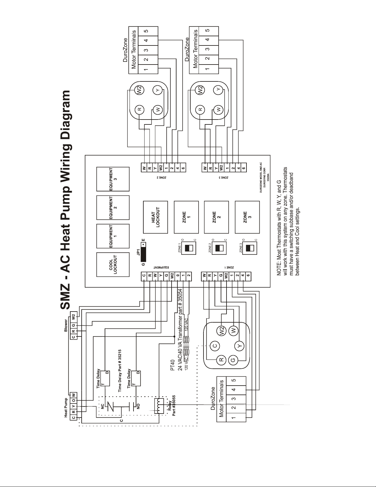
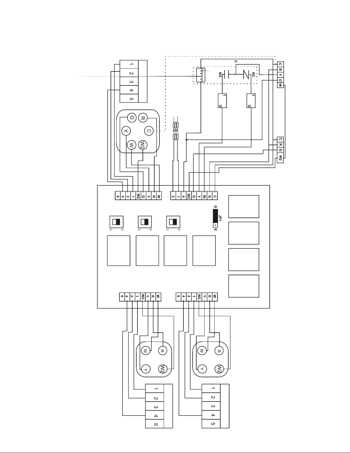
DuroZone INSTRUCCIONES PARA CABLEADO DE SMZ-AC, PÁGINA 5
PROCEDIMIENTO DE VERIFICACIÓN DEL SISTEMA SMZ-AC
El siguiente procedimiento de verificación requiere un voltímetro ajustado en 24 voltios AC. Si después de completar el procedimiento
de verificación el panel SMZ-AC y los dampers están funcionando correctamente pero el sistema no, verifique cuidadosamente el
cableado. Los problemas más comunes son un cable mal colocado, una mala conexión o un cable roto. Si el problema no parece ser
ninguno de estos, verifique los termostatos y el equipo. DEBE REALIZAR LOS SIGUIENTES PROCEDIMIENTOS DE PRUEBA
EN LA SECUENCIA INDICADA. NO OMITA NINGUNO DE LOS PASOS. COLOQUE TODOS LOS CONMUTADORES
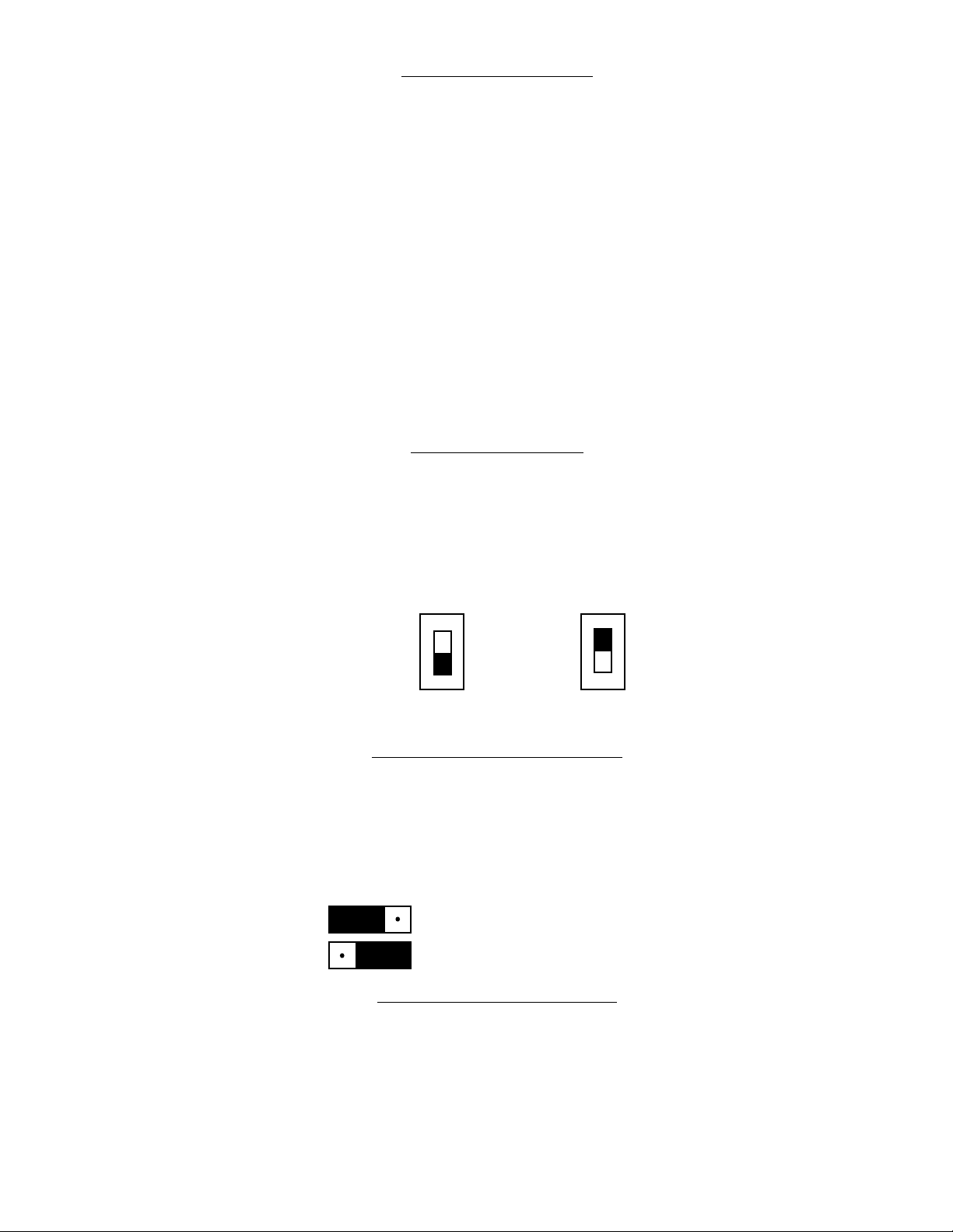
DE LOS DAMPERS EN LA POSICIÓN “O” (ABIERTO).
1. Debe tener 24 voltios en R y C de la placa de bornes de equipo del panel SMZ-AC. (Esto alimenta al panel SMZ-AC y
al equipo).
2. Debe tener 24 voltios en 1 y 2 de la placa de bornes de equipo del panel SMZ-AC, y en cada 1 y 2 de cada terminal de zona
del panel SMZ-AC. (Esto alimenta los reguladores/dampers).
3. Para verificar el funcionamiento del panel SMZ-AC, debe desconectar todos los termostatos. Con los termostatos desconectados
y 24 voltios como se describe en el número 2 arriba, todos los dampers deben estar abiertos. (Si los dampers no están abiertos,
proceda con el paso 4).
3A. Para verificar el modo calor, realice la desviación de R a W en la placa de bornes de la Zona 1 del panel SMZ-AC. La Zona 1
demandará calor. (Todos los dampers, excepto el de la Zona 1, se cerrarán, y el calderas se encenderá). El relé de bloqueo de
frío y el relé de la Zona 1 se activarán (Se encenderá el indicador de la luz roja). Las Zonas 2 o 3 pueden activarse realizando
la desviación de W y R en las correspondientes placas de bornes de las Zonas 2 o 3 del SMZ-AC. Si el calderas no se activa,
con R y G desviados, verifique los 24 voltios en C y W en la placa de bornes del equipo del panel SMZ-AC. Si la lectura del
voltaje es 24 voltios, el panel SMZ-AC está bien.
3B. Para verificar el modo frío, desconecte la conexión R y W realizada para la verificación del modo calor en el paso 3A. Realice
la desviación de R e Y a la placa de bornes de la Zona 1 del panel SMZ-AC. La Zona 1 demandará calor. (Todos los dampers,
excepto el de la Zona 1, se cerrarán, y el aire acondicionado se encenderá). El relé de bloqueo de calor, el relé del equipo 1
y el relé de la Zona 1 se activarán (Se encenderá el indicador de la luz roja). Las Zonas 2 o 3 pueden activarse realizando la
desviación de R e Y en las correspondientes placas de bornes de las Zonas 2 o 3 del SMZ-AC. Si el aire acondicionado no se
activa, verifique los 24 voltios en C e Y en la placa de bornes del equipo del panel SMZ-AC. Si la lectura del voltaje es 24
voltios, el panel SMZ-AC está bien.
3C. Para verificar el ventilador, desvíe R y G en la placa de bornes de la Zona 1 del panel SMZ-AC. Asegúrese de que por lo menos
un conmutador de regulador esté en la posición “OPEN” (“O”) (ABIERTO). El ventilador debe activarse. Si el ventilador
no se activa, con R y G desviados, verifique los 24 voltios en C y G en la placa de bornes del equipo del panel SMZ-AC. Si la
lectura del voltaje es 24 voltios, el panel está bien.
4. Para verificar el funcionamiento de los dampers, realice el paso 3A, verificando los 24 voltios en 1 y 4 de la placa de bornes
de cada zona del panel SMZ-AC que esté activada, y los voltios de “O” en 1 y 4 de la placa de bornes de cada zona del panel
SMZ-AC que no esté activada. (IMPORTANTE: Esta prueba funcionará solo si hay por lo menos una zona activada. Si no hay
ninguna zona activada, todas las lecturas de voltajes de 1 y 4 serán 24 voltios). Si todas las lecturas son correctas, el panel
está funcionando correctamente. Si algún regulador no está funcionando, pero la prueba del panel SMZ-AC determinó que el
panel funciona bien, verifique los 24 voltios en las terminales 1 y 2 del motor del regulador. Si hay 24 voltios, desconecte la
conexión de la terminal 4 al regulador. El desvío de las terminales 4 y 5 del motor del regulador debería hacer que se abriera
el regulador. (La apertura total del regulador llevará de 30 a 60 segundos). Cuando desconecte el conmutador de derivación
de las terminales 4 y 5, el regulador debe cerrarse. Si el regulador verificado no funciona como se describe, el problema podría
ser la conexión del enganche del regulador, que el movimiento de las hojas está siendo obstruido, o que el motor es incorrecto
o presenta alguna falla. (Con los dampers de múltiples hojas, es posible conectar el motor al enganche 180 “fuera de fase”, lo
que hace que el regulador se abra cuando debe estar cerrado, y se cierre cuando debería estar abierto).