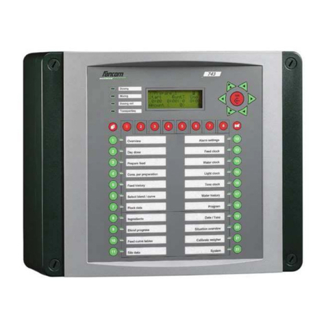
Fancom 743 User guide

GB
743
INSTALLER MANUAL
VERSION C3

Fancom 743 Copyright
Fancom B.V. Limited Warranty Statement
Fancom expressly warrants each new product manufactured by it to be free from defects in material or
workmanship for two years from the date of initial installation by or for the original purchaser, but in no
event shall such period be greater than two years and three months from the date of initial shipment of the
product from the manufacturer's facility. The following warranties are in lieu of any and all representations
and warranties, express or implied, including the implied warranties of merchantability or fitness for a
particular purpose, whether arising from statute, common law, custom or otherwise. Fancom shall not be
liable for any special, consequential or incidental damages resulting from the use of any of the products or
caused by any defect, failure or malfunction, whether a claim for such damage is based upon warranty,
contract, negligence or otherwise, and in no event shall Fancom be liable for any damages in excess of the
amount paid for the products. In the event a defect is found by the Manufacturer to exist within this period,
the Manufacturer will, at its option, (a) repair or replace such product free of charge, F.O.B. the factory of
manufacture, or (b) refund to the original purchase price to the original purchaser, in lieu of such repair or
replacement. Labour costs associated with the replacement or repair of the product are not covered by the
Manufacturer.
WARNING: Independent alarm installation
Like all mechanical and electronic devices, the Fancom Control Unit may fail. Thus, when the Fancom
Control Unit is controlling the environment for confined livestock, it is highly recommended by Fancom that
an independent alarm system be installed. The Fancom Control Unit does provide a connection port
designated for either make or break contact for the sounding of an alarm condition (please refer to
installation guide for location). Failure to comply with the above warning may result in loss of product
and/or profits, for which Fancom is not responsible or liable.
.
All rights reserved. Reproduction of any part of this manual in any form whatsoever without Fancom’s
express written permission is forbidden. The contents of this manual are subject to change without notice.
All efforts have been made to assure the accuracy of the contents of this manual. However, should any
errors be detected, Fancom would greatly appreciate being informed of them. The above notwithstanding,
Fancom can assume no responsibility for any errors in this manual or their consequence.
Copyright 2010 Fancom B.V.
Panningen, the Netherlands
MODIFICATIONS RESERVED
Art.Nr. A5911215
GB100203
Always keep this manual by your computer
Fancom 743 Table of contents
Table of contents
About this manual
1. Introduction........................................................................................................................................1
2. Technical specifications .....................................................................................................................2
3. Safety instructions and warnings .....................................................................................................3
3.1 General........................................................................................................................................3
3.2 During installation.....................................................................................................................3
3.3 During repairs ............................................................................................................................3
3.4 Independent alarm system ........................................................................................................3
4. Mounting and installation.................................................................................................................4
5. System settings ..................................................................................................................................5
5.1 General........................................................................................................................................5
5.2 Configuration..............................................................................................................................6
5.2.1 General...............................................................................................................................6
5.2.2 Communication .................................................................................................................7
5.3 Installation .................................................................................................................................8
5.3.1 General...............................................................................................................................8
5.3.2 Silo......................................................................................................................................9
5.3.3 Additive ..............................................................................................................................9
5.3.4 Weigher ............................................................................................................................10
5.3.5 Circuit ..............................................................................................................................12
5.3.6 Storage silo ......................................................................................................................13
5.3.7 Feed clock.........................................................................................................................15
5.3.8 Water clock ......................................................................................................................16
5.3.9 Light clock........................................................................................................................16
5.3.10Time clock.......................................................................................................................17
5.4 Internal RAM............................................................................................................................17
APPENDIX 1: System alarms
APPENDIX 2: Installation report
APPENDIX 3: Possible dosing out situations
APPENDIX 4: Connection diagrams

Fancom 743 About this manual
About this manual
This manual contains information about the installation and service of the computer. Read this
manual carefully and follow all safety instructions. The installer’s settings can then be entered
and the computer prepared for further use.
This manual has been written by Fancom for the installer. A user’s manual is also available for the
user. The user’s manual contains information about the daily use of the computer.
If you have any questions regarding the computer, please do not hesitate to contact your Fancom
dealer. The subjects discussed in this manual are listed in the table of contents.
The following symbols are used in this manual:
Suggestions, advice and notes with additional information.
Caution
The product could be damaged, if the procedures are not followed carefully.
Caution
Life threatening situation, if the procedures are not followed carefully.

Fancom 743 1. Introduction
1
1. Introduction
The Fancom 743 is a feed mixing computer for the poultry sector. It is suitable for fully automatic
control of a feed mixing installation.
Maximum installation size
♦12 stock silos
♦12 ingredients
♦1 weigher, possibly with mixer
♦1 hopper including proximity switch
♦16 storage silos (incl. prox. feedback)
♦4 additives
♦2 circuit auger controls
♦16 storage silo selection valves
♦16 storage silo augers
♦16 feed clocks
♦16 water clocks
♦16 pulse inputs for the water meter
♦16 light clocks, controllable or on/ off
♦16 extra time clocks
♦16 pulse relays
Communication
The computer can be connected in a network or serial communication loop (using a
communication connector print). The 743 computer can be operated by a remote Personal
Computer.

Fancom 743 INSTALLER: 2. Technical specifications
2
2. Technical specifications
Power supply
Mains voltage
230Vac (-10% +6%)
Mains frequency
50-60Hz
Maximum power consumption
50VA
Available power supply for sensors and equipment
24Vdc (fused)
max. 500mA
12Vdc, short circuit resistant
max. 150mA
13 Relay outputs
Relay 1-12, voltage free*
max. 2A 60Vdc/30Vac or max. 2A 250Vac
Relay 13 (alarm relay, voltage free)
max. 2A 60Vdc/30Vac
10 Analog outputs (8 bits)
Voltage range
0-10Vdc
Maximum load
1mA
Output resistance
570Ω
8 Contact inputs
Open contact voltage (high level)
12Vdc
Low level
<1.5Vdc
Application:
Counter input, min. pulse width 2.5mSec
frequency input
max. frequency 200Hz
max. frequency 5kHz
1 Weigher input, resolution 12 bits (not for commercial purposes)
Excitation
10Vdc
Max. input voltage
20 mVdc
Max. load
2 × 350
Ω
weighing bar
Max. cable length
40 m
Housing
Plastic housing with screw on lid
IP54
Dimensions (l×w×h)
300×360×140mm/11.8×14.2×5.5ins.
Weight (unpacked)
3.9kg/8.6lbs
Ambient climate
Operating temperature range
0
°
C to +40
°
C/32
°
F to 104
°
F
Storage temperature range
-10
°
C to 50
°
C/14
°
F to 122
°
F
Relative humidity
< 95%, uncondensed
Communication
FNet, Fancom network, for intercommunication of control computers and PC connection*.
Optional: Fancom serial loop for intercommunication of control computers and PC connection*
I/O-Net for extra in and outputs using I/O-modules; max. 30 IDM and/or IRM-modules, each with 16
in/outputs*.
- max pulse frequency IDM input:
- max. pulse frequency IRM output:
25/sec.
0.5/sec.
*
For electrical connection and/or cable data, see connection diagrams.

Fancom 743 INSTALLER: 3. Safety instructions and warnings
3
3. Safety instructions and warnings
3.1 General
Read the safety instructions carefully before installing and using the computer. The installation
of the computer and trouble shooting must be carried out by an authorized technician/installer,
according to the prevailing standards. Fancom takes no responsibility for any possible damage as
a result of incorrect settings and a non- or partially functioning installation.
3.2 During installation
1. Take precautions against electrostatic discharge (ESD) when working on the computer.
2. Provide a clean and dry place to work.
Disconnect power before installation.
3. Use correct wires as shown on the connection diagrams (appendix) and follow all instructions.
4. Make all wiring connections and check them before applying power.
Incorrect wiring may cause permanent damage.
Concerning the USA and Canada
To simplify wiring the computer it is advisable to mount a 4” x 4” wireway below the
computer. Two 1 ¼” conduits running between the computer and the wireway should be
used, one for high voltage wire (rights side) and one for control voltage and sensors (left
sid
e). Seal conduits after connection to prevent entry of dust, aggressive gases and/or
humidity. Use only shielded wire for sensors and control. Wires are to enter the computer
and all Fancom computers from the bottom only!
3.3 During repairs
Never work on a computer with the power switched on.
Before a new fuse is placed, the cause of the defect should be remedied by an authorized
installer. Replace a defective fuse only by a fuse of the same type (see connection
diagram).
3.4 Independent alarm system
A computer is a piece of electronic apparatus, a possible technical malfunction should be taken
into account.
Caution
Fancom advises the installation of an extra, independent alarm system, for example, a
min/max thermostat. This is highly recommended with systems where technical
malfunctioning can cause considerable damage. An alarm connection diagram can be
found in the appendix.

Fancom 743 INSTALLER: 4. Mounting and installation
4
4. Mounting and installation
Caution
It is essential that the alarm outputs of each computer are connected to a separate alarm system
circuitry.
When mounting the computer, the following should be observed:
1. Never mount the computer near water pipes, drainage pipes etc.
2. Never mount the computer in a place where the weather has direct influence (not in the sun,
not in places where the temperature can rise sharply, etc.).
3. Never mount the computer in a humid and/or dusty room and certainly not in the room where
the animals are present.
No condensation may take place in or on the computer.
4. Use the holes behind the cover screws on the corners of the box to securely fasten the
computer.
5. Mount the computer on a flat surface with the display at eye level (or higher). Ensure that the
gland nuts are at the bottom of the computer
6. Use gland nuts for the connection of the computer. Use the sealing plates supplied to seal the
gland nuts which are not used. Seal all gland nuts after connection to prevent the entry of
dust, aggressive gases and/or humidity.
7. Ensure that the frequency and voltage for which this computer is made are the same as the
voltage and frequency present.
8. To protect against lightning, place an over voltage protection device in the power supply of the
computer.
9. Connect each computer to its own circuit breaker from the main electrical service panel.
10. It should be possible to disconnect the computer using a bipolar mains switch or plug.
Ensure the computer is well grounded.
11. Separate high and low voltage wires by mounting them in separate cable channels.
12. If metal cable channels are used, ground them.
Always observe the regulations of the electricity company
Advice
Limit the length of the signal wires much as possible; avoid crossing high/low voltage wires.

Fancom 743 INSTALLER: 5. System settings
5
5. System settings
5.1 General
The system settings are intended for the installer. Normally the user will never have to change
these settings, with the exception of the password.
The system settings are not for daily use. The installer makes these settings when the weighing
computer is installed. All system settings are protected by a password. The password is a
combination of maximum five function keys. As long as the password is unchanged, this is key
. Chapter 7 in the user manual describes how to change the password.
The system settings are divided into three groups:
1 Configuration
2 Installation
3 Internal RAM

Fancom 743 INSTALLER: 5. System settings
6
5.2 Configuration
5.2.1 General
New password
See chapter 7 of the user manual.
Time
The actual time in hours and minutes. This time can be altered, for
example, when changing from summer to winter time.
Date
The actual date.
Synchr. time
If the “master” must send the time to the other computers, enter whether
this should take place every 16 minutes or once a day. This should also be
entered for the “slaves”. They will adopt the time from the “master”.
Unit temp.
Enter the unit of temperature:
°C = degrees Celsius
°F = degrees Fahrenheit
Unit windspeed
Enter the unit of wind speed:
m/s = metres per second
Mph = miles per hour (1 m/s ~ 2.24 Mph).
Version:
743 software version number.
2×
>>Configuration
1 General
2 Communication
>>General
New password
Time 14:52
Date Su 14-03-99
Synchr.time NO
Unit temp. °C
Unit windspeed m/s
Version 743 C2.0

Fancom 743 INSTALLER: 5. System settings
7
5.2.2 Communication
Computer
number
If the computer is part of a loop or network, each computer should have its
own, unique number.
Preferably use a corresponding number for the computer and the
storage silo.
Type
Enter whether the computer functions as “master” or “slave”. The “master” is
the computer which controls communication. All the other computers in the
loop (L) or network (N) should be set as “slave”.
Baud rate
All the computers in a loop should have the same Baud rate setting. The loop
communication normally works at 2400Bd. If a modem of 1200Bd is used, all
the other computers in the loop should also be set to 1200Bd.
Comm. R...,T .....
Communication counters with loop communication for receive (Receive) and
transmit (Transmit). These counters can be used to trace faulty
communication connections. In this case set all the counters on all the
computers to “0”. No
rmally these counters increase simultaneously.
Communication has failed between the last computer where the counters are
increasing simultaneously, and the first computer where the counters are not
increasing at the same speed.
Network status
If several computers are connected via a network, the network status can be
controlled. The network status is a value between 0 and 5. If the value is 5,
the connection is in order. Every other value (0, 1, 2, 3 or 4) indicates that
the network connection is not (yet) in order.
127 means that there is only one computer in the network.
>>Communication
Computer number 1
Type: L SLAVE
Baud rate 2400 Bd
Comm R: 0 T: 0
Network status 0

Fancom 743 INSTALLER: 5. System settings
8
5.3 Installation
5.3.1 General
A number of settings and assignments are made concerning the installation. Fancom divides the
installation settings into ten groups:
External alarm
Enter the address (in front of the point) and the digital input number (behind
the point) to which the external alarm has been connected.
Day change
Enter at what time a day period ends.
>>Installation
1 General
2 Silo
3 Additive
4 Weigher
5 Circuit
6 Storage silo
7 Feed system clock
8 Water clock
9 Light clock
10 Time clock
>>General
External alarm 0. 0
Day change 0:00
2×

Fancom 743 INSTALLER: 5. System settings
9
5.3.2 Silo
Relay output
Enter the address (in front of the point) and the relay number (behind the
point) to which the silo auger has been connected.
Status
The silo auger status: OFF (silo auger not active) or ON (silo auger active).
Wait time inc.
Enter within how many minutes and seconds after dosing in has started the
weigher content must increase.
Min.inc./30sec
Enter the minimum weigher content (kg) increase each 30 seconds during
ingredient dosing in. The maximum dosing in time per ingredient is 10
minutes (600 seconds). If the weigher capacity is set to a value greater than
600 kg, the maximum dosing in time per ingredient is equal to the weigher
capacity in seconds. Example
: a weigher capacity of 1200 kg equals a
maximum dosing in time of 1200 seconds per ingredient.
After flow
When dosing in has stopped certain ingredients can still fall into the weigher
(after flow). This after flow is a computer calculated value. When the 743 is
started the after flow is 0.0kg. Enter an (estimated) after flow for the first
time the 743 is put into operation.
Wait aft. dos. in
Enter here how long (minutes and seconds) the computer should wait after
an ingredient has been dosed in before determining a stable weight.
5.3.3 Additive
Relay output
Enter the address (in front of the point) and the relay number (behind the
point) to which the dosing in mechanism for this additive has been
connected.
Status
Status
shows if an additive is currently being added (ON) or not (OFF).
Pulse input
Enter the address (in front of the point) and the digital input number (behind
the point) to which the pulse giver (when dosing in is based on pulses) for
this additive has been connected.
>>Additive_1
Relay output 0. 0
Status OFF
Pulse input 0. 0
next additive (max. 4 additives)
previous additive
2×
>>Silo_1
Relay output 0. 0
Status OFF
Wait time inc. 0:00
Min.inc./30sec 0.0
After flow 0.0
Wait aft.dos.in 0:00
next silo (max.12 silos)
previous silo

Fancom 743 INSTALLER: 5. System settings
10
5.3.4 Weigher
Weigher
content
The current weigher content (accurate to the gram).
Valve status
The current unloading valve status under the weighing hopper: OPEN or
CLOSE.
Motor control
Enter the time (accurate to tenths of seconds) needed by the motor to fully open
or close the unloading valve. This time depends on the type of weigher
(weighing drum ~ 4 sec.; steel weighing hopper ~ 0.8 sec.).
Weigher type
Enter the type of weigher:
WHOP-MOT
Standing steel weigher with a valve motor controlled in one
direction (motor control).
WGDRUM
Polyester, hanging weigher with a valve motor controlled in two
directions.
WHOP-RIN
Standing steel weigher with a valve controlled by a solenoid
(rinse control).
OUT-AUG
Dosing out auger direct from the weigher
Weigher tare
The weight (accurate to the gram) of the empty weigher.
Capacity
Enter the portion size (kg).
Address ILM
Enter the ILM module address (0-31). The value 0 means that the load-cells are
connected directly.
3×
>>Weigher
Weigher content 0. 0
Valve status CLOSE
Motor control 0.0
Weigher type WHOP-RIN
Weigher tare 0.000
Capacity 0.0
Address ILM 0
Counts 0
Zero/offset 0
Span 0
Filter 0
Stable 0.000
Hopper NO
Max.sensor 0. 0
Min.sensor 0. 0
Empty hopper 0:00
Mixer relay 0. 0
Status OFF
Wait time dec. 0:00
Min.dec./30sec 0.000
Empty weigher 0:00
Block during Tr NO
Simulation NO
Increase 0.000
Decrease 0.000
Status DECREASE

Fancom 743 INSTALLER: 5. System settings
11
Counts
The weighing bar signal (rough measurement).
Zero/Offset
A calculated value corresponding to the zero setting of the ILM.x/weigher
combination.
Span (Cal.)
A calculated value corresponding to the calibrated ILM.x/weigher combination.
The computer uses the values of
Span
and
Zero/Offset
and the rough
weighing bar signal
Counts
to calculate the actual weigher weight (
Weight
).
If the empty weight changes, because a lid has been added for example, the
zero point must be re-
adjusted. If the weighing bars and/or ILM.x are
changed, repeat zero setting and calibration.
Filter
The number of measurements (maximum 25), used by the computer to
determine an average stable weight.
Stable
The difference (accurate to the gram) between the highest and lowest
measurement used by the computer to determine a stable weight.
Hopper
Enter whether there is a hopper.
Max. sensor
Enter the address (in front of the point) and the digital input number (behind
the point) to which the maximum sensor has been connected.
Min. sensor
Enter the address (in front of the point) and the digital input number (behind
the point) to which the minimum sensor has been connected.
Empty hopper
Enter within how much time (minutes and seconds) the hopper should be empty
(min. sensor free)
Mixer relay
Enter the address (in front of the point) and the relay number (behind the point)
to which the mixer has been connected.
Status
Status shows whether the mixer is active (ON) or not (OFF).
Wait time dec.
Enter within how many minutes and seconds the weigher content must
decrease after dosing out has started.
Min.dec./30sec
Enter the minimum weigher content (kg) decrease each 30 seconds during blend
dosing out.
Empty weigher
Enter within how much time (minutes and seconds) the weigher should be
empty after the unloading valve has been opened.
Block during TR
Enter if feed may be prepared when there is feed on transport.
Simulation
YES
Simulation mode
NO
Normal mode
The following settings are important if
Simulation
is set to YES.
Increase
Enter the weight increase for simulation mode.
Decrease
Enter the weight decrease for simulation mode.
Status
Status of the weigher content in simulation mode: INCREASE or DECREASE.

Fancom 743 INSTALLER: 5. System settings
12
5.3.5 Circuit
Relay output
Enter the address (in front of the point) and the relay number (behind the
point) to which the circuit inlet valve control has been connected.
Status
The current status of the circuit inlet.
Extra distance
The distance (minutes and seconds) between two feed columns*. Select this
distance so that the two feed columns cannot mix.
% slip
As the pressure of feed in the weigher decreases the feed column will be
spread more thinly over the auger. This means that the column will become
longer resulting in an increased transport time to the storage silo.
Enter the expected extra transport time here as a percentage.
∗
A feed column consists of one or more successive portions for the same storage silo.
Fig. 1: Feed columns illustrated
Feed column
for storage silo 2
Feed column
for storage silo 1
slip
slip
slip
slip
slip
Extra distance
>>Circuit_1
Relay output 0. 0
Status OFF
Extra distance 0:00
% slip 0
next circuit (max. 2 circuits)
previous circuit
4×

Fancom 743 INSTALLER: 5. System settings
13
5.3.6 Storage silo
Circuit number
Enter to which circuit this storage silo belongs:
0 = no circuit; 1 = circuit 1; 2 = circuit 2.
Port. to max. sens
Enter how many portions can still fit into this storage silo, if the maximum
sensor is not covered (
Stor. silo dem. =
DEMAND).
Port. to fill. sens
Enter how many portions can still fit into this storage silo, if the filling
sensor is not covered (
Stor. silo dem. =
FILL).
Valve position
Enter how long it will take (minutes and seconds) before the feed reaches the
reverse valve after dosing out has started.
Reverse valve
Enter how long (minutes and seconds) the reverse valve needs to open or
close fully.
Auger aft. run
Enter how long (minutes and seconds) the storage silo auger must continue
running after the feed has passed the reverse valve.
5×
>>Storage silo
1
Circuitnummer 0
Port.tot max.sens 0
Port.tot afv.sens 0
Positie klep 0:00
Omschakel.klep 0:00
Auger nalopen 0:00
Max.senser 0. 0
Afvulsensor 0. 0
Min.sensor 0. 0
Relay auger 0. 0
Status OFF
Relay klep 0. 0
Status OFF
Relay pulse 0. 0
Status OFF
Hvh / voerpulse
>>Storage silo
1
Circuit number 0
Port.to max.sens 0
Port.to fill.sens 0
Valve position 0:00
Reverse valve 0:0
Auger aft.run. 0:00
Stor.silo dem. DEM
Max.sensor 0. 0
Fill.sensor 0. 0
Min.sensor 0. 0
Relay auger 0. 0
Status OFF
Relay valve 0. 0
Status OFF
Relay pulse 0. 0
Status OFF
Am./feed pulse 0.0
%Tolerance 100
Batch am. 250.0
Max. Batch 2000.0
Min. Batch 250.0
Release house 0. 0
Status OFF

Fancom 743 INSTALLER: 5. System settings
14
Stor. silo dem.
FULL
The storage silo is full.
DEMAND
The storage silo demands blend preparation.
FILL
Filling sensor covered
WITHOUT filling sensor WITH filling sensor Combination
FILL/MIN sensor
Fig. 2: Storage silo demand illustrated
Max. sensor
Enter the address (in front of the point) and the digital input number (behind
the point) to which the maximum sensor has been connected.
Fill. sensor
Enter the address (in front of the point) and the digital input number (behind
the point) to which the filling sensor has been connected.
Min. sensor
Enter the address (in front of the point) and the digital input number (behind
the point) to which the minimum sensor has been connected.
Relay auger
Enter the address (in front of the point) and the relay number (behind the
point) to which the storage silo auger control has been connected.
Status
The current storage silo auger status: ON (storage silo auger running) or
OFF (storage silo auger idle).
Relay valve
Enter the address (in front of the point) and the relay number (behind the
point) to which the reverse valve control has been connected.
Status
The current pulse giver status: ON (sending pulses) or OFF (not sending
pulses).
Relay pulse
Enter the address (in front of the point) and the relay number (behind the
point) to which the pulse counter has been connected.
Status
The current pulse counter status: ON (pulse counter counting pulses) or OFF
(pulse counter not counting pulses). This can also be used as feed registration
by an external process computer.
Am./feed pulse
Enter how much feed (kg) corresponds to one feed pulse.
Max. sensor
Filling sensor
Min. sensor
FULL
DEMAND
FILL
Max. sensor
Min. sensor
FULL
DEMAND
Max. sensor
Min./Filling sensor
FULL
DEMAND
FILL

Fancom 743 INSTALLER: 5. System settings
15
The following settings are important in registration mode.
%Tolerance
A factory setting used by the computer to determine the batch amount.
Batch am.
The amount of feed to be fed according to the daily norm × the tolerance
percentage.
This amount is limited by the minimum and maximum batch.
Max. Batch
The maximum amount of feed to be prepared in the weigher.
Min. Batch
The minimum amount of feed to be prepared in the weigher
When the animals are growing and a weigher with a large capacity is used, there can be large
amounts of feed in the storage silo, especially in the case of young animals. Sometimes the feed is
stored in the silo for days. To prevent this, use the self-determining
Batch am.
The norm table
must be filled in, even if registration mode is used. In this case the day amount is unlimited, but
the batch size is variable (smaller batches for young animals).
Example:
Weigher capacity = 2000kg
Feed amount according to norm:
20.000 chicks × 25gr. = 500kg × 50% tolerance = 250kg.
Batch size is 250kg.
Release house
Enter the address (in front of the point) and the relay number (behind the
point) to which the release house control has been connected.
Status
The current release house status: ON or OFF.
Status = ON:
-During registration, when a feed preparation time is active.
-During dosing/registering, as long as the feed preparation time is active
and the feed amount for this preparation time has not been completely
dosed and transported.
5.3.7 Feed clock
Relay output
Enter the address (in front of the point) and the relay number (behind the
point) to which the feed clock control has been connected.
Status
The current feed clock status: ON (feed system active) or OFF (feed system
not active).
>>Feed clock
1
Relay output 0. 0
Status OFF
6×

Fancom 743 INSTALLER: 5. System settings
16
5.3.8 Water clock
Pulse input
Enter the address (in front of the point) and the digital input number (behind
the point) to which the water pulse counter has been connected.
Relay output
Enter the address (in front of the point) and the relay number (behind the
point) to which the water clock control has been connected.
Status
The current water clock status: ON (water clock active) or OFF (water clock
not active).
Unit/pulse
Enter how much water (litres) corresponds to one water pulse.
5.3.9 Light clock
Relay output
Enter the address (in front of the point) and the relay number (behind the
point) to which the light clock control has been connected.
Status
The current light clock status: ON (light clock active) or OFF (light clock not
active).
Analog output
Enter the analog output number to which the light clock analog control has
been connected.
Type
Enter the type of analog control: 0-10V or 10-0V.
>>Water clock
1
Pulse input 0. 0
Relay output 0. 0
Status OFF
Unit/pulse 0.0
7×
>>Light clock
1
Relay output 0. 0
Status OFF
Analog output 0
Type 0-10V
8×
Other manuals for 743
1
Table of contents
Other Fancom Control System manuals

Fancom
Fancom LUMINA 71 User manual

Fancom
Fancom LUMINA 41 User manual

Fancom
Fancom VLR.6 User manual

Fancom
Fancom IMS User manual

Fancom
Fancom ITM-iF User manual

Fancom
Fancom FB.1 User manual

Fancom
Fancom 750 User manual

Fancom
Fancom LUMINA 38 User manual

Fancom
Fancom INTELLITEK User manual

Fancom
Fancom MRK.2 User manual
Popular Control System manuals by other brands

Mi-Light
Mi-Light LS3 User instruction

Balcrank
Balcrank PGM-40 Operation, installation, maintenance and repair guide

ONEFINITY
ONEFINITY Elite Series Installation and operation instruction

Lite-Check
Lite-Check VERIFIER 1010 user guide

Lectrotab
Lectrotab JLC Series Installation & operation

Strand
Strand Vision.net RS232 user manual