Delta VFD-C2000 User manual

VFD-C2000
PROFINET Communication Card
Operation Manual
20181106

VFD-C2000 PROFINET Communication Card CMC-PN01
CMC-PN01 Operation Manual
2
Caution
This operation manual provides information on specifications, installation instructions, basic
operations/configurations, and details on network communication protocols.
The AC motor drive is a sophisticated product powered by electricity. For the safety of the
operator and your mechanical equipment, only qualified electrical engineers are allowed to
perform the installation/test runs and make parameter adjustments. If you have any question
or concern, please contact your local Delta distributor. Our professional staff will be very glad
to help you.
Please read this manual carefully and follow the instructions completely to avoid device
damage or personal injury.

VFD-C2000 PROFINET Communication Card CMC-PN01
CMC-PN01 Operation Manual
3
Table of Contents
1Introduction .......................................................................................................................4
1.1 Introduction to PROFINET IO Communication.....................................................................4
1.2 Features ...............................................................................................................................4
1.3 Network Functions and Specifications..................................................................................4
2Product Appearance and Components...........................................................................6
2.1 Exterior Dimensions .............................................................................................................6
2.2 Introduction to Each Component..........................................................................................6
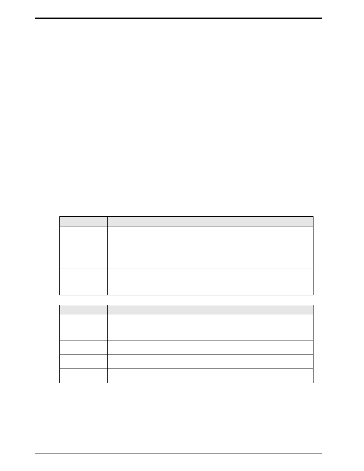
2.3 LED Indicators......................................................................................................................7
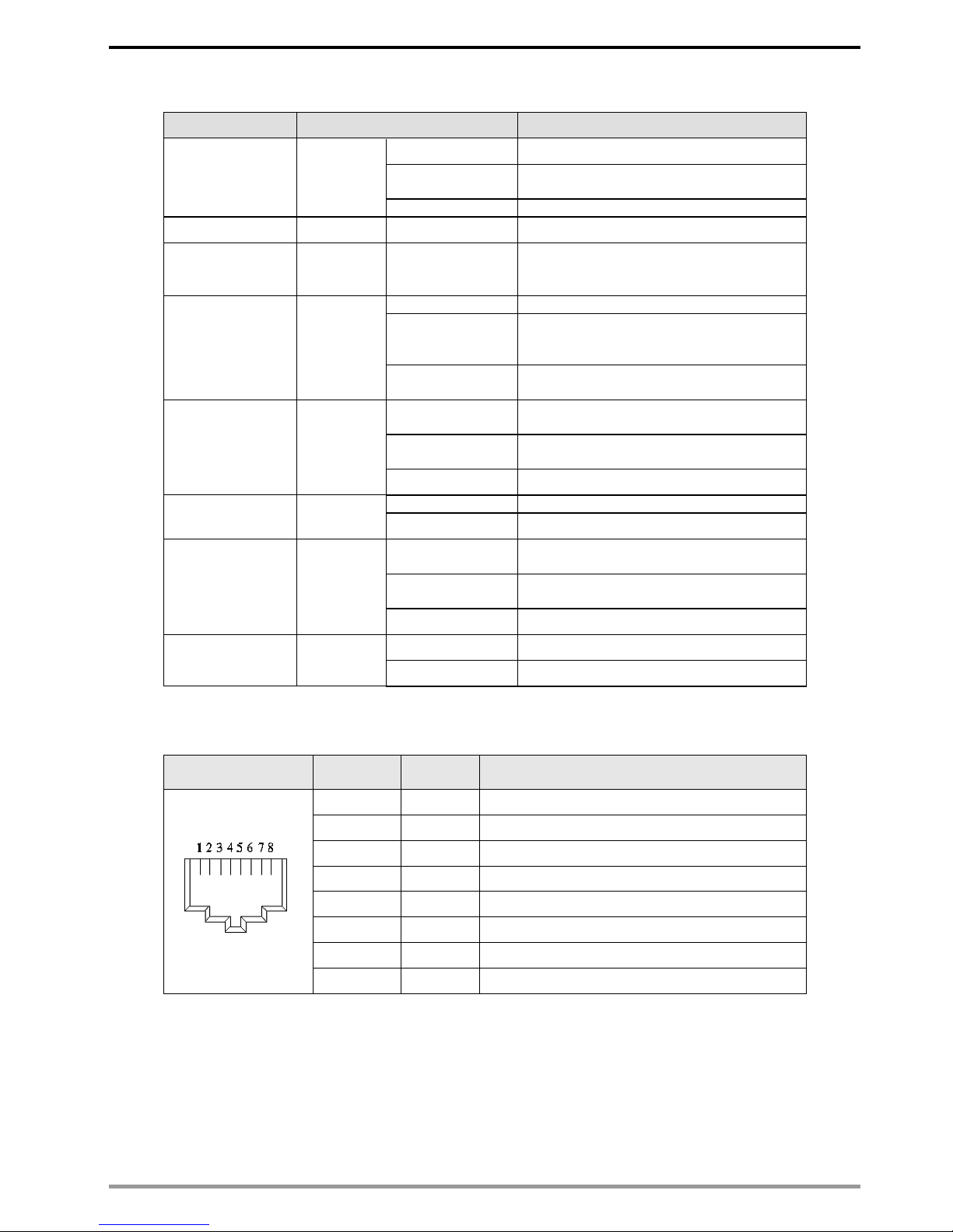
2.4 Definition of RJ45 Pin...........................................................................................................7
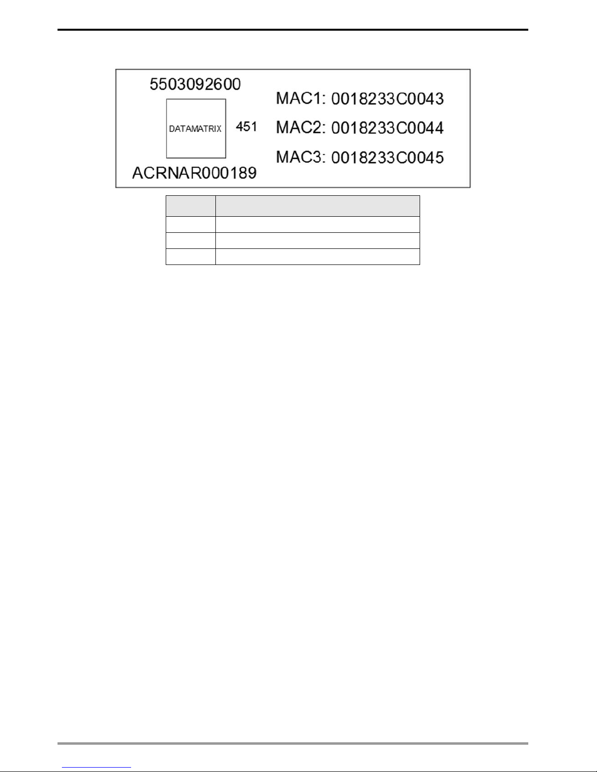
2.5 MAC Address Label..............................................................................................................8
3Installation and Wiring......................................................................................................9
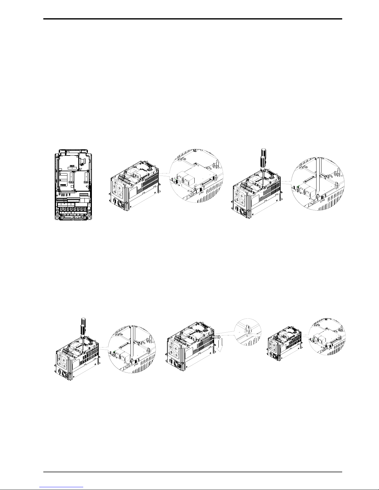
3.1 Installation ............................................................................................................................9
3.2 Unloading .............................................................................................................................9
3.3 Connecting to the Network .................................................................................................10
4VFD-C2000 Drive Settings ..............................................................................................11
5PROFINET Communication Profile................................................................................12
5.1 Synchronous Parameter Access in Delta-specific Mode (Tables for Control Word and Status
Word)..................................................................................................................................12
5.2 Asynchronous Parameter Access.......................................................................................16
5.3 Identification and Maintenance Functions (I&M) ................................................................17
5.4 Disconnection Treatment....................................................................................................17
6Connection Configuration to Host Controller...............................................................18
6.1 Basic Configuration ............................................................................................................18
6.2 Speed Mode DEMO (S7-300 + STEP 7)............................................................................23
6.3 Speed Mode DEMO (S7-1500 + TIAPORTAL)..................................................................33
6.4 Demonstration of Reading/Wrting Synchronous and Asynchronous Parameters (S7-300 +
TIA PORTAL)......................................................................................................................42

VFD-C2000 PROFINET Communication Card CMC-PN01
CMC-PN01 Operation Manual
4
1 Introduction
1.1 Introduction to PROFINET IO Communication
PROFINET IO is a fieldbus, a family of industrial computer network protocols, and
serves as a communication between programmable logic controllers (PLC) and
distributed field equipment for EtherNet. This protocol recognizes three classes of
devices, IO Controllers, IO Supervisors and IO Devices, and uses three different
communication channels to exchange data: Standard UDP/IP & TCP/IP Channel,
Real-Time (RT) Channel, and Isochronous Real-Time (IRT) Channel. Standard UDP/IP
& TCP/IP Channel is used to parameterize and configure device and asynchronous
operation; RT Channel is used for synchronous data transmission and warning; IRT
Channel is applied to motion control.
1.2 Features
CMC-PN01 connects C2000 drive to PROFINET to exchange data with the host
controller easily. This simple network solution saves cost and time for connection and
installation of factory automation. Moreover, its components are compatible with
suppliers’.
By installing CMC-PN01 in C2000 through the main PROFINET device, you can:
1. Control the drive through PROFINET
2. Modify the drive’s parameters through PROFINET
3. Monitor the drive’s status through PROFINET
1.3 Network Functions and Specifications
EtherNet Specifications
Item
Specifications
Interface
RJ45
Number of ports
2 ports
Communication
Mode
IEEE 802.3
Cable
Category 5e shielding 100 M
Transmission
speed
10/100 Mbps auto-negotiate
Communication
protocol
PROFINET
Environmental Conditions
Item
Specifications
Noise immunity
ESD (IEC 61800-5-1, IEC 6100-4-2)
EFT (IEC 61800-5-1, IEC 6100-4-4)
Surge Teat (IEC 61800-5-1, IEC 6100-4-5)
Conducted Susceptibility Test (IEC 61800-5-1, IEC 6100-4-6)
Operating
temperature
-10–50°C (temperature), 90% (humidity)
Storage
temperature
-25–70°C (temperature), 95% (humidity)
Vibration/Shock
resistance
International standards
IEC 61800-5-1, IEC 60068-2-6/IEC 61800-5-1, IEC 60068-2-27

VFD-C2000 PROFINET Communication Card CMC-PN01
CMC-PN01 Operation Manual
5
Electrical Specifications
Item
Specifications
Power supply
voltage
5 VDC
Power
consumption
0.8 W
Insulation voltage
500 VDC
Weight
(g; approx.)
27 (g)

VFD-C2000 PROFINET Communication Card CMC-PN01
CMC-PN01 Operation Manual
6
2 Product Appearance and Components
2.1 Exterior Dimensions
Unit: mm [inch]
2.2 Introduction to Each Component
1. Screw fastening hole
9. ACT PHY1 indicator (Port 1)
2. Positioning hole for communication card
10.Link PHY1 indicator (Port 1)
3. Ready out indicator
11. ON/OFF Switch
4. MT out indicator
12. Fool-proof groove on the communication
card
5. SD indicator
13. RJ45 connection port (Port 2)
6. BF out indicator
14. RJ45 connection port (Port 1)
7. ACT PHY2 indicator (Port 2)
15. Control panel connection port
8. Link PHY2 indicator (Port 2)

VFD-C2000 PROFINET Communication Card CMC-PN01
CMC-PN01 Operation Manual
7
2.3 LED Indicators
Name
Indicator Status
Indication
Ready out indicator
Yellow LED
Always on
PN Stack normal activation
Flashing
PN Stack normal activation, waiting for
synchronizing with MCU.
Off
PN Stack abnormal activation
MT out indicator
Green LED
-
-
SD indicator
Red LED
-
-
BF out indicator
Red LED
Always on
Disconnected with PROFINET Controller
Flashing
Normal connection, but abnormal
communication with PROFINET
Controller.
Off
Normal connection with PROFINET
Controller
ACT PHY1
indicator
Orange LED
Always on
Connected and is exchanging data with
Master regularly
Flashing
Not connected but is handshaking data
with Master
Off
Initial status
LINK PHY1
indicator
Green LED
Always on
Normal network connection
Off
Not connected to network
ACT PHY2
indicator
Orange LED
Always on
Connected and is exchanging data with
Master regularly
Flashing
Not connected but is handshaking data
with Master
Off
Initial status
LINK PHY2
indicator
Green LED
Always on
Normal network connection
Off
Not connected to network
2.4 Definition of RJ45 Pin
RJ45 Pinout
Diagram
PIN
Definition
Description
1
Tx+
Positive pole for data transmission
2
Tx-
Negative pole for data transmission
3
Rx+
Positive pole for receiving data
4
--
N/C
5
--
N/C
6
Rx-
Negative pole for receiving data
7
--
N/C
8
--
N/C

VFD-C2000 PROFINET Communication Card CMC-PN01
CMC-PN01 Operation Manual
8
2.5 MAC Address Label
Definition
Description
MAC1
Port 1 MAC Address
MAC2
Port 2 MAC Address
MAC3
Interface MAC Address

VFD-C2000 PROFINET Communication Card CMC-PN01
CMC-PN01 Operation Manual
9
3 Installation and Wiring
This section introduces how CMC-PN01 connects to VFD-C2000 and to network.
3.1 Installation
How to connect CMC-PN01 to VFD-C2000:
Shut off the power supply to the AC motor drive.
Open the front cover of the AC motor drive.
Place the insulation spacer into the positioning pin at Slot 1 (see Figure 1), and
line-up the two holes on the PCB at the positioning pin. Press the pin to clip the
holes on the PCB (see Figure 2).
Ensure the PCB is securely placed, and then fix the screws with 6–8 kg-cm of torque
(5.21–6.94 lb-in.) as shown in Figure 3.
Figure 1
Figure 2
Figure 3
3.2 Unloading
How to detach CMC-PN01 from VFD-C2000:
Shut off the power supply to the AC motor drive.
Open the front cover of the AC motor drive.
Remove the two screws (see Figure 4).
Pull to open the card clip and put a flat-head screwdriver into the groove to pry the
PCB off the card clip (see Figure 5).
Release the other card clip to remove the PCB (see Figure 6).
Figure 4
Figure 5
Figure 6
DC-
DC++1
+2
B1
B2
CAUTION
CL001
禁止移除上蓋,
維修除外。
Do not remove
this cover,except
for servicing
警 告
B1 B2
DC++1
+2
DC-
M
直流共母?
3
DC-/DC+
MOTOR /
制? ? 阻
電源
POWER /

VFD-C2000 PROFINET Communication Card CMC-PN01
CMC-PN01 Operation Manual
10
3.3 Connecting to the Network
The wiring of CMC-PN01 shows as follows:
When the installation is finished, supply electricity to the drive. The Pr.09-60 of the
drive should be able to display “PROFINET”with a current value of 12. If not, make sure
your version of the drive is correct (C2000 needs 2.04 or later versions) and the
communication card is correctly connected.

VFD-C2000 PROFINET Communication Card CMC-PN01
CMC-PN01 Operation Manual
11
4 VFD-C2000 Drive Settings
When you operate VFD-C2000 through CMC-PN01, you should set the
communication card as the source of VFD-C2000 controls and settings. You need to use
the keypad to configure the following parameter addresses to the corresponding values:
Note: To make PLC or the host controller identify CMC-PN01, it is necessary to load the
product description file (GSDML). You can download it directly from Delta’s official
website.
Keypad
Parameter No.
Settings/
Displayed Value
Description of Function
Pr.00-20
8
Set communication card as the source of frequency command.
Pr.00-21
5
Set communication card as the source of control.
Pr.09-30
1
Decoding method is either 60xx or 20xx.
Pr.09-60
12
Communication card identification:
When CMC-PN01 communication card is connected, the value of
this parameter displays “12”.

VFD-C2000 PROFINET Communication Card CMC-PN01
CMC-PN01 Operation Manual
12
5 PROFINET Communication Profile
1. Synchronous parameter access in Delta-specific mode
2. Asynchronous parameter access
3. Identification & Maintenance functions (I&M)
4. Disconnection Treatment
5.1 Synchronous Parameter Access in Delta-specific Mode (Tables for
Control Word and Status Word)
Table 1: 60xx Output Message (Host ControllerDrive) (Pr.09-30=1)
Bytes
Order
Address
Attribute
bit
Value
bit
User
Rights
Speed Mode
Position Mode
Home Mode
Torque Mode
Notes
0
LSB
6000h
RW
0
0
CMD_ACT
4
fcmd=0
None
Stop Home
Tcmd=0
Pulse 0
1
fcmd=Fset(Fpid)
Tcmd=Test
Requires
SERVO_ON=1
Pulse 1
POScmd=
POSset
Execute
Home once
Requires
SERVO_ON=1
1
0
EXT_CMD1
4
FWD run
command
Change when
drive stops
1
REV run
command
Immediate
change
2
0
EXT_CMD2
4
Absolute
movement
1
Relative
movement
3
0
HALT
3
drive runs till
target speed
reaches
drive runs till
target position
reaches
Continue to
return to home
Feed
(Continue to run
to target torque)
1
drive stops by
declaration
setting
Lock (drive
stops at current
position by
declaration
setting)
drive stops at
current
position by
declaration
setting
Lock (torque
stops at current
speed)
4
0
LOCk
4
drive runs till
target speed
reaches
1
frequency stops
at current
frequency
5
0
JOG
4
JOG OFF
JOG OFF
JOG OFF
JOG OFF
1
Pulse 1
JOG RUN
JOG RUN
JOG RUN
JOG RUN
6
0
QSTOP
2
None
None
None
None
1
Quick Stop
Quick Stop
Quick Stop
Quick Stop
7
0
SERVO_ON
1
Servo OFF
Servo OFF
Servo OFF
Servo OFF
1
Servo ON
Servo ON
Servo ON
Servo ON
1
MSB
11–8
0000
GEAR
4
Main speed
Main position
Main torque
0001–
1111
1st–15th speed
and frequency
selection
1st–15th position
selection
13–12
00
ACC/DEC
4
1st Acceleration
time
1st Acceleration
time
01
2nd Acceleration
time
2nd
Acceleration
time
10
3rd Acceleration
time
3rd Acceleration
time
11
4th Acceleration
time
4th Acceleration
time
14
0
EN_SW
4
Multi-step
command and
Multi-step
command and
Multi-step
command and

VFD-C2000 PROFINET Communication Card CMC-PN01
CMC-PN01 Operation Manual
13
acceleration/
deceleration time
switching are not
allowed
acceleration/
deceleration
time switching
are not allowed
acceleration/
deceleration time
switching are not
allowed
1
Multi-step
command and
acceleration/
deceleration time
switching are
allowed
Multi-step
command and
acceleration/
deceleration
time switching
are allowed
Multi-step
command and
acceleration/
deceleration time
switching are
allowed
15
Pulse 1
RST
4
Clear error code
Clear error code
Clear error
code
Clear error code
2
LSB
6001h
RW
Mode
Cmd
3
MSB
4
LSB
6002h
RW
Velocity
Cmd
Velocity
Cmd
Speed command
(without
numbers)
Profile velocity
(without
numbers)
Profile velocity
(without
numbers)
5
MSB
6
LSB
6003h
RW
7
MSB
8
LSB
6004h
RW
Pos Cmd
Pos
Cmd
Position
command
(with numbers)
9
MSB
10
LSB
6005h
RW
11
MSB
12
LSB
6006h
RW
Torq Cmd
Torq
Cmd
Torque
command
(with numbers)
13
MSB
14
LSB
6007h
RW
Reserved
Reserved
Reserved
Reserved
15
MSB
16
LSB
6008h
RW
Reserved
Reserved
Reserved
Reserved
17
MSB
18
LSB
6009h
RW
Reserved
Reserved
Reserved
Reserved
19
MSB
Table 2: 61xx Input Message (DriveHost Controller) (Pr.09-30=1)
Bytes
Order
Address
Attribute
bit
Value
bit
Speed
Mode
Position
Mode
Home
Mode
Torque
Mode
Notes
0
LSB
6100h
R
0
0
ARRIVE
Frequency
command
not
reached
Position
command
not
reached
Zero
command
unfinished
Torque
command
not
reached
1
Frequency
command
arrival
Position
command
reached
Zero
command
completed
Torque
command
reached
1
0
DIR
FWD
FWD
FWD
FWD
1
REV
REV
REV
REV
2
0
WARN
No
warning
No
warning
No
warning
No
warning
1
Warning
occurred
Warning
occurred
Warning
occurred
Warning
occurred
3
0
ERROR
No error
No error
No error
No error
1
Error
occurred
Error
occurred
Error
occurred
Error
occurred
5
0
JOG
None
None
None
None
1
On JOG
On JOG
On JOG
On JOG
6
0
QSTOP
None
None
None
None
1
On Quick
Stop
On Quick
Stop
On Quick
Stop
On Quick
Stop
7
0
SERVO_ON
PWM
OFF
PWM
OFF
PWM
OFF
PWM
OFF
1
PWM ON
PWM ON
PWM ON
PWM ON
1
MSB
8
0
Ready
Ready
OFF
Ready
OFF
Ready
OFF
Ready
OFF
1
Ready
ON
Ready
ON
Ready
ON
Ready
ON
15–9
2
LSB
6101h
R
Mode Cmd
3
MSB
4
LSB
6102h
R
Velocity
cmd
Actual
output
Actual
output
Actual
output
Actual
output
5
MSB

VFD-C2000 PROFINET Communication Card CMC-PN01
CMC-PN01 Operation Manual
14
frequency
frequency
frequency
frequency
6
LSB
6103h
R
7
MSB
8
LSB
6104h
R
Pos Cmd
Actual
position
(absolute)
Actual
position
(absolute)
Actual
position
(absolute)
Actual
position
(absolute)
9
MSB
10
LSB
6105h
R
11
MSB
12
LSB
6106h
R
Torq Cmd
Actual
torque
Actual
torque
Actual
torque
Actual
torque
13
MSB
14
LSB
6107h
R
Reserved
Reserved
Reserved
Reserved
15
MSB
16
LSB
6108h
R
Reserved
Reserved
Reserved
Reserved
17
MSB
18
LSB
6109h
R
Reserved
Reserved
Reserved
Reserved
19
MSB
Table 3: 20xx Output Message (Host ControllerDrive) (Pr.09-30=0)
Bytes
Order
Command
Address
Attribute
Value
Definition
Description
0
LSB
Operation
Command
2000h
W
b1–10
00: No function
Operation command unchanged
1. Bits in this column are used for
operating actions. The commands are
one-shot and run only when VFD
receives commands. Therefore, Master
only needs to issue the command once.
VFD always runs the command issued by
Master unless new commands are
issued.
2. Bits in this column work only when VFD
sets parameter selection operation
command source as communication.
01: Stop
Stop operation command
10: Run
Normal command operation
11: JOG+Run
JOG command
b3–b2
Not used
b5–b4
00: No function
Direction command unchanged
1. Bits in this column are used for
operating actions. The commands are
one-shot and run only when VFD
receives commands. Therefore, Master
only needs to issue the command once.
VFD always runs the command issued by
Master unless new commands are
issued.
2. Bits in this column work only when VFD
sets parameter selection operation
command source as communication.
01: FWD
FWD direction command
10: REV
REV direction command
11:Change direction
Change current direction
command
b7–b6
00: 1st Accel./Decel. time
1st acceleration/deceleration time
selection
Bits in this column are used for switching
acceleration or deceleration time through
communication when VFD operates.
Parameter VFD can provide four kinds of
settings for acceleration or deceleration
time and use one-shot method to switch
by bits in this column.
01: 2nd Accel./Decel. time
2nd acceleration/deceleration
time selection
10: 3rd Accel./Decel. time
3rd acceleration/deceleration time
selection
11: 4th Accel./Decel. time
4th acceleration/deceleration time
selection
1
MSB
b11–b8
0000: Main speed
Multi-step speed and frequency
switching selection
1. Bits in this column are used for
switching VFD’s operation frequency
through communication. Parameter VFD
can provide 15 kinds of settings for
operating speed and use one-shot
method to switch by bits in this column.
2. You have to set 2000h b12=1 or you
cannot use this multi-step speed and
frequency switching function through
communication.
3. If you want to know the current running
speed of this multi-step speed and
frequency switching function, check
address 2017h.
0001: 1st step speed
0010: 2nd step speed
0011: 3rd step speed
0100: 4th step speed
0101: 5th step speed
0110: 6th step speed
0111: 7th step speed
1000: 8th step speed
1001: 9th step speed
1010: 10th step speed
1011: 11th step speed
1100: 12th step speed
1101: 13th step speed
1110: 14th step speed
1111: 15th step speed
b12
1: Enable b11–b6
Enable multi-step speed and
frequency and acceleration or
deceleration time switching
function
b14–b13
00: No function
Switching for operation command
source
Bits in this column are used for enforcedly
switching operation command source
through communication. If VFD operation
source setting is not controlled by
communication, you can use the bits in
this column to enforcedly switch to
communication or restore to parameter
setting.
01: Operation command controlled
by PU
10: Operation command by Pr.
setting
11: Switch between PU and Pr.
setting
b15
2
LSB
Speed
Set Point
Command
2001h
W
b15–b0
VFD Set Point Command
VFD multi-unit setup command
1. Bits in this column are used for issuing
setting commands to VFD through
communication. The default unit for this
setting is Hz or otherwise (can be known
from 211Dh bit12). If the units are Desc,
address 2123h–2124h can be read.
2. Bits in this column work only when VFD
frequency source parameter is set as the
3
MSB

VFD-C2000 PROFINET Communication Card CMC-PN01
CMC-PN01 Operation Manual
15
way of communication.
4
LSB
VFD
Fault/Control
Command
2002h
W
b0
1:EF (external fault) ON
External Fault (EF) enabled
1. This bit is used for triggering an
external fault to VFD to stop the running
status. The method for stopping can be
set by VFD parameter.
2. This bit operates by on-shot method
and this fault can only be restored by
Fault Reset command.
b1
1: Reset
Fault Reset command
This bit is used for resetting the status
from Fault to Ready.
b2
1: b.b. ON
External B.B. (Base Block)
enabled
This bit is used for triggering an external
B.B. to VFD to pause the running status.
When bit=0 (BB is dismissed), VFD
immediately returns to its former status.
b3
1: HAND-ON/LOC-ON command
HAND/LOCAL frequency
operation source enabled
Whether switching HAND/AUTO or
LOC/REM would lead to running STOP
depends on motor drive’s parameter
settings.
b4
1: AUTO-ON/REM-ON command
AUTO/REMOTE frequency
operation source enabled
5
MSB
b15–b5
Not used
6
LSB
2003h
W
b15–b0
Reserved
Reserved
Reserved
7
MSB
8
LSB
2004h
W
b15–b0
Reserved
Reserved
Reserved
9
MSB
10
LSB
2005h
W
b15–b0
Reserved
Reserved
Reserved
11
MSB
12
LSB
2006h
W
b15–b0
Reserved
Reserved
Reserved
13
MSB
14
LSB
2007h
W
b15–b0
Reserved
Reserved
Reserved
15
MSB
16
LSB
2008h
W
b15–b0
Reserved
Reserved
Reserved
17
MSB
18
LSB
2009h
W
b15–b0
Reserved
Reserved
Reserved
19
MSB
Table 4: 21xx Input Message (DriveHost Controller) (Pr.09-30=0)
Bytes
Order
Command
Address
Attribute
Value
Definition
Description
0
LSB
Fault
Status
2100h
R
b7–b0
Error Code
Fault codes
Bits in this column are used for checking if VFD
occurs any fault, and using the fault codes to
substitute 32XXh to obtain the description strings for
the fault.
1
MSB
b15–b8
Warn Code
Warning
codes
Bits in this column are used for checking if VFD
occurs any warnings, and using the warning codes to
substitute 33XXh to obtain the description strings for
the fault.
2
LSB
Operation
Status
2101h
R
b1–b10
00: RUN LED light off, STOP LED
light up (Drive Stop)
Run and stop
status
Bits in this column are used for checking VFD’s
running status in order to control its LED display.
01: RUN LED blink, STOP LED light
up (Drive Decelerate during the
drive stopping)
10: RUN LED light up, STOP LED
blink (Drive standby)
11: RUN LED light up, STOP LED
light off (Drive Run)
b2
1: JOG active
JOG running
status
b4–b3
00: REV LED light off, FWD LED
light up (Forward)
Operation
direction
status
Bits in this column are used for checking VFD’s
running direction status in order to control its LED
display.
01: REV LED blink, FWD LED light
up (Reverse to Forward)
10: REV LED light up, FWD LED
blink (Forward to Reverse)
11: REV LED light up, FWD LED
light off (Reverse)
b5
1: Factory parameters opened
Factory
parameter
ON/OFF
status (not
used)
b6
Reserved
b7
1: Operation command controlled by
external terminal
Bits in this column are used for checking whether
VFD’s current operation command source is external
terminal or not. If bit=1, external terminal has the
highest processing priority. Master communication
can obtain control rights only when it switches
operation command source by 2000h b14–13.
3
MSB
b8
1: Main Freq. controlled by
communication
Bits in this column are used for checking the current
VFD frequency command source.
b9
1: Main Freq. controlled by external
terminal (AI)
b10
1: Operation command controlled by
Communication
Bits in this column are used for checking whether the
current VFD operation command source are
communication or not.
b11
1: Parameters been locked
Parameter
Lock ON/OFF
status
Bits in this column are used for checking whether
VFD’s parameters are locked or not. If bit=1, the
values for reading parameters are always 0.
b12
0: AC drive stop, 1: AC drive run
VFD actual
running output
status
(RUNNING=1)
b13
Jog command
JOG running

VFD-C2000 PROFINET Communication Card CMC-PN01
CMC-PN01 Operation Manual
16
command
status
(CMDJOG=1)
b14
b15
4
LSB
VFD
Variable
Monitor
2102h
R
b15–b0
Frequency Command
Bits in this column are used for displaying VFD’s
current running frequency command values (2dot
value) with its unit Hz.
5
MSB
6
LSB
2103h
R
b15–b0
Output Frequency
Bits in this column are used for displaying VFD’s
current output frequency values (two-dot value) with
its unit Hz.
7
MSB
8
LSB
2104h
R
b15–b0
Output Current
Bits in this column are used for displaying VFD’s
current output current values (one-dot value) with its
unit A.
9
MSB
10
LSB
2105h
R
b15–b0
DC BUS Voltage
Bits in this column are used for displaying VFD’s
current DC BUS voltage values (one-dot value) with
its unit V.
11
MSB
12
LSB
2106h
R
b15–b0
Output Voltage
Bits in this column are used for displaying VFD’s
current output voltage values (one-dot value) with its
unit V.
13
MSB
14
LSB
2107h
R
b15–b0
Multi-step speed
Bits in this column are used for displaying VFD’s
current multi-step speed and frequency values.
15
MSB
16
LSB
2108h
R
b15–b0
17
MSB
18
LSB
2109h
R
b15–b0
Value of the counter
19
MSB
20
LSB
210Ah
R
b15–b0
Power factor angle (0–180.0
degree)
21
MSB
22
LSB
210Bh
R
b15–b0
Torque (xxxx.x N-M)
23
MSB
24
LSB
210Ch
R
b15–b0
Motor speed (rpm)
25
MSB
26
LSB
210Dh
R
b15–b0
PG feedback pulse count
27
MSB
28
LSB
210Eh
R
b15–b0
PG reference pulse count
29
MSB
30
LSB
210Fh
R
b15–b0
Output Power (xx.xxkW)
31
MSB
Table 5: Disconnection Treatment (CMC-PN01Drive)
5.2 Asynchronous Parameter Access
Host controller PROFINET sends a write request first, then CMC-PN01 determines
whether the host controller needs to read or write in accordance with the Operation field in
the packet, and read or write drive’s parameters through the contents of Data Block.
If there is no problem for the packet and CMC-PN01 is not in a busy mode, CMC-PN01
sends a write response to make the host controller be aware that CMC-PN1 has received the
packet delivered and performed corresponding actions accordingly.
If the host controller requests to read the parameters, CMC-PN01 needs to send a read
request after sending a write response. Then CMC-PN01 reads the corresponding
parameters of the drive and replies to the host controller in the packet of read response.
The table below shows the definitions of the packet:
Field(s)
Description
Range
Type
Service
Request or Response service.
Request (0x00)
Response (0x80)
UI8
Operation
Read or Write operation.
Write (0x08)
Read (0x09)
UI8
Block Length
Length of the block.
0…0xFFFF
UI16
ARUUID
Identifier
- time low
- time mid
- time high and version –clock –node
-
UI32
UI16
UI16
Qctet[2]
Qctet[6]
API
Application Process Identifier
Device Access Point (0x000)
UI32
PROFIdrive (0x3A00)
Slot
Slot of the Module Access Point (MAP/PAP)
0x01
U16
Sub-slot
Sub-slot of the Module Access Point (MAP/PAP)
0x01
U16
Padding
2 bytes
Index
Index of the Record Data Object
0x0001–0x7FFF
0xB02E
U16
Data length
Length of the data block
0…0xFFFFFFFF
UI32
Address
Attribute
Value
Definition
Description
2505h
R
P9-63
Card Fault
This section is only allowed to be written by the
card.
This address can correspond to VFD’s
communication parameter.

VFD-C2000 PROFINET Communication Card CMC-PN01
CMC-PN01 Operation Manual
17
Additional value 1
(response only)
Field for transferring additional data
-
UI16
Additional value 2
(response only)
Field for transferring additional data
-
UI16
Padding
24 bytes for request; 20 bytes for response.
Data block
Used only with request and read response.
The timing diagram of parameter access shows as follows:
5.3 Identification and Maintenance Functions (I&M)
Identification and maintenance (I&M) is to provide you with supports in adjustment,
test, parameterization and repair.
CMC-PN01 supports I&M0 functions and access by read requests that record data
objects.
The table below shows the data structure of I&M0 functions:
Content
Size
Description
Header
10 bytes
-
Vendor ID
2 bytes
PROFINET Vendor ID of Delta, which is 0x03BF.
Order ID
20 bytes
Order number
Serial number
16 bytes
Serial number
Hardware revision
2 bytes
Hardware revision
Software revision
4 bytes
Revision of the software
Revision counter
2 bytes
Number of revision
Profile ID
2 bytes
0x00
Profile specific type
2 bytes
No profile specific type (0x0000)
I&M version
2 bytes
Version 1.1 (0x0101)
Supported I&M functions
2 bytes
I&M0 is supported (0x0001).
5.4 Disconnection Treatment
When PROFINET is disconnected, CMC-PN01 performs the following settings to
ensure safety.
1. Set 2505H = 81Ecto indicates CMC-PN01 occurs a disconnection failure
2. Set 6000H = 0
3. Set 2000H = 1
When PROFINET connection restores, it resumes performing commands from the
host controller.

VFD-C2000 PROFINET Communication Card CMC-PN01
CMC-PN01 Operation Manual
18
6 Connection Configuration to Host Controller
This section introduces how Siemens STEP 7 and TIA PORTAL PLC integral
software, as well as Siemens PLC S7-300 and S7-1500 use PROFINET to connect C2000
drive. The connection configuration shows as the figure below. Siemens PLC connects
CMC-PN01 communication card of C2000 drive through the EtherNet.
6.1 Basic Configuration
The Settings for Communication
1. Start your PC and set IP address configuration as static IP address. It is recommended
to set the address to 192.168.xxx.xxx in the red box as the figure below shows.

VFD-C2000 PROFINET Communication Card CMC-PN01
CMC-PN01 Operation Manual
19
2. Use Siemens STEP 7 to look up the host controller’s IP address. In the screen of
HW Config, perform the function under PLCEtherNetEdit EtherNet Node as
the figure below shows.
Click Browse button to search the available device on the Internet.

VFD-C2000 PROFINET Communication Card CMC-PN01
CMC-PN01 Operation Manual
20
When it finishes searching, a screen displays as shown in the figure below. The IP address
displays 192.168.16.26.
If the IP address of your computer is set as a different one, it is recommended to reset your
PC’s IP address to make it consistent with PLC’s domain.
※Note: If the IP address of your computer is different from PLC’s domain, you are unable
to download the program to PLC.
3. Using Siemens TIAPORTAL to search PLC IP address. Start TIA PORTAL, select
Online&Diagnostics, and then click Project view.
Table of contents