Demco 32 HD User manual

8H000019, Rev AE
10/23
COMBINE HEADER TRANSPORT
Heavy Duty
32 HD
38 HD
42 HD
48 HD
52 HD
SERIAL NUMBERS: 11680 - ABOVE

Introduction/General Information.................................................................................................3
Safety ...................................................................................................................................... 4-6
Safety Decals ..............................................................................................................................7
Maintenance Schedule................................................................................................................8
Bolt Torque Requirements ........................................................................................................10
Wheel Nut Torque Requirements .............................................................................................11
7K Front Idler Suspension & Hub Breakdown...........................................................................12
7K Front Brake Suspension & Hub Breakdown.........................................................................13
Bearing Inspection/Lubrication ..................................................................................................14
Seal Inspection/Bearing Adjustment..........................................................................................15
E-Z Lube Lubrication .................................................................................................................16
Electric Brakes Adjustment........................................................................................................17
Wiring Schematic With Brakes ............................................................................................ 18-19
Break-Away System ............................................................................................................ 20-21
Header Alignment Tape .............................................................................................................22
Header Securement ..................................................................................................................23
Adjustable Tie-Down..................................................................................................................24
52’ Top Rail Tube Extension .....................................................................................................25
710 Telescoping Tongue Breakdown .................................................................................. 26-27
460 Telescoping Tongue Breakdown................................................................................... 28-29
Main Parts Breakdown ........................................................................................................ 30-31
7K Front Fender Breakdown ............................................................................................... 32-33
Optional Spare Tire Carrier........................................................................................................34
GVW Ratings.............................................................................................................................35
Head Transport Check List ........................................................................................................36
Dealer Instructions.....................................................................................................................37
Table of Contents
TABLE OF CONTENTS
INTRODUCTION . . . . . . . . . . . . . . . . . . . . . . . . . . . . . . . . . . . . . . . . . . . . . . ii
SPECIFICATIONS / GENERAL INFORMATION . . . . . . . . . . . . . . . . . . . . . . . . . . . . . . . 1
SAFETY DECALS . . . . . . . . . . . . . . . . . . . . . . . . . . . . . . . . . . . . . . . . . . . . . . . 2
SAFETY RULES . . . . . . . . . . . . . . . . . . . . . . . . . . . . . . . . . . . . . . . . . . . . . . 3 - 5
DEALER INSTRUCTIONS . . . . . . . . . . . . . . . . . . . . . . . . . . . . . . . . . . . . . . . . . . . . 6
OPERATION . . . . . . . . . . . . . . . . . . . . . . . . . . . . . . . . . . . . . . . . . . . . . . . . . 7 - 8
TROUBLE SHOOTING. . . . . . . . . . . . . . . . . . . . . . . . . . . . . . . . . . . . . . . . . . . . . . . . . 9
OWNER SERVICE . . . . . . . . . . . . . . . . . . . . . . . . . . . . . . . . . . . . . . . . . . . . . . . . . 10
PARTS CATALOG . . . . . . . . . . . . . . . . . . . . . . . . . . . . . . . . . . . . . . . . . . . . . . . . 11 - 13
BOLT SIZE AND BOLT TORQUE CHART . . . . . . . . . . . . . . . . . . . . . . . . . . . . . . . . . . 14
WARRANTY . . . . . . . . . . . . . . . . . . . . . . . . . . . . . . . . . . . . . . . . . . . . . . . . . . . . 15
WARRANTY FOR PARTS . . . . . . . . . . . . . . . . . . . . . . . . . . . . . . . . . . . . . . . . . . . . 16
Table of Contents
Page 2 8H000019

3. When placing a parts order, refer to this manual
for proper part numbers and place order by
PART NO. and DESCRIPTION.
4. Read assembly instructions carefully. Study
assembly procedures and all illustrations before
you begin assembly. Note which parts are used
in each step. This unit must be assembled in
proper sequence or complications will result.
1. Unless otherwise specied, high-strength
(grade5) (3 radial-line head markings) hex head
bolts are used throughout assembly of this
piece of equipment.
2. Whenever terms “LEFT” and “RIGHT” are used
in this manual it means from a position behind
the combine head transport and facing forward.
Never overload combine head transport. Do not exceed the load rating of
the axle or load rating of tires, whichever is less.
Ensure that anybody present is clear before applying power to any machin-
ery used in conjunction with the combine head transport or when moving
the transport.
Never allow anyone on combine head transport during travel, loading, or
unloading of combine head.
DO NOT exceed the tire manufacturer’s recommended safe towing speeds.
Thank you for purchasing a Demco Combine Head Transport. We feel you have made a wise choice and
hope you are completely satised with your new piece of equipment. Proper care and use will result in
many years of service.
Throughout this manual, the term IMPORTANT is used to indicate that failure to observe can cause
damage to equipment. The terms CAUTION, WARNING and DANGER are used in conjunction with the
Safety-Alert Symbol (a triangle with an exclamation mark) to indicate the degree of hazard for items of
personal safety.
This Safety-Alert Symbol indicates a hazard and means ATTENTION!
BECOME ALERT! YOUR SAFETY IS INVOLVED!
Indicates an imminently hazardous situation that, if not avoided, will result in
death or serious injury.
Indicates a potentially hazardous situation that, if not avoided, could result in
death or serious injury, and include hazards that are exposed when guards
are removed.
Indicates a potentially hazardous situation that, if not avoided, may result in
minor or moderate injury.
Indicates that failure to observe can cause damage to equipment.
Indicates helpful information.
IMPORTANT
NOTE
WARNING
CAUTION
DANGER
WARNING: To Avoid Personal Injury or Death, Observe
the following Instructions:
WARRANTY POLICY, OPERATOR MANUALS, PARTS MANUALS & REGISTRATION
Go online to www.demco-products.com to review Demco warranty policies, operator manuals and register your Demco product.
GENERAL INFORMATION
INTRODUCTION
8H000019 Page 3

SAFETY
is not qualied to operate the machine. An untrained
operator exposes himself and bystanders to possible
serious injury or death.
• Never exceed limits of a piece of machinery. If its
ability to do a job or to do so safely is in question, DON’T
TRY IT.
• Do not use unit until you are sure that area is clear,
especially around children and animals.
PREPARATION
• Always wear relatively tight and belted clothing to
avoid getting caught in moving parts. Wear sturdy,
rough-soled work shoes and protective equipment for
eyes, hair, hands, hearing, and head; and respirator or
lter mask where appropriate.
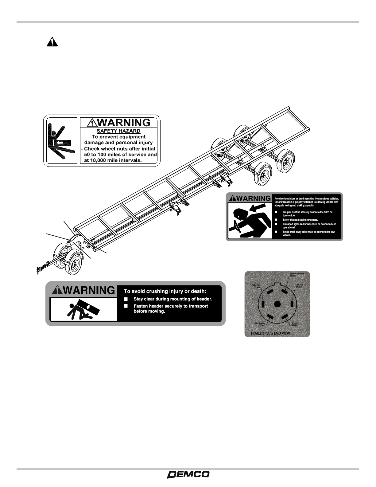
• Keep wheel and lug nuts tightened to specied torque.
Assure that tires are inated evenly.
• Give unit a visual inspection for any loose bolts, worn
parts, or cracked welds, and make necessary repairs.
Follow maintenance safety instructions in this manual.
• Make sure there are not tools lying on or in equipment.
• Make sure that brakes are evenly adjusted (if equipped
with brakes).
• Do not allow anyone to stand between tongue or hitch
and towing vehicle when backing up to equipment.
TRANSPORTATION
• Always comply with all state and local laws governing
highway safety and movement of farm machinery on
public roads. Local laws should also be checked for all
highway lighting and marking requirements.
• If equipment is going to be transported on a public
highway, always follow state and local regulations
regarding safety chains. Be sure to check with local
law enforcement agencies for your own particular
regulations. If required safety chains should be obtained
and installed, only safety chains (not elastic or nylon/
plastic tow straps) should be used to retain connection
between towing and towed machines in event of
separation of primary attaching system. Use a high
strength, appropriate size hitch pin with a mechanical
retainer and attach safety chains. Crisscross chains
under tongue and secure to draw bar cage, mounting
loops, or bumper frame.
Safety is a primary concern in the design and
manufacture of our products. Unfortunately, our eorts
to provide safe equipment can be wiped out by an
operator’s single careless act.
Every year many accidents occur which could have been
avoided by a few seconds of thought and a more careful
approach to handling equipment. You, the operator,
can avoid many accidents by observing the following
precautions in this section. To avoid personal injury,
study the following precautions and insist those working
with you, and you yourself, follow them.
In addition to the design and conguration of equipment,
hazard control and accident prevention are dependent
upon the awareness, concern, judgment, and proper
training of personnel involved in the operation, transport,
maintenance and storage of equipment.
In order to provide a better view, certain illustrations
in this manual may show an assembly with a safety
shield removed. However, equipment should never be
operated in this condition. Keep all shields in place. If
shield removal becomes necessary for repairs, replace
shield prior to use.
It has been said “The best safety device is an informed,
careful operator.” We ask you to be that kind of operator.
TRAINING
• Safety instructions are important! Read all attachment
manuals; follow all safety rules and safety decal
information. Failure to follow instructions or safety rules
can result in serious injury or death
• Don’t hurry the learning process or take unit for granted
in becoming familiar with your new equipment.
• If you do not understand any part of this manual
and need assistance, see your dealer. (Replacement
manuals are available from selling dealer.)
• Operators must be instructed in and be capable of the
safe operation of the equipment, its attachments, and all
controls. Do not allow anyone to operate this equipment
without proper instructions.
• Never allow children or untrained persons to operate
equipment.
• Train all new personnel and review instructions
frequently with existing workers. A person who has not
read and understood all operating and safety instructions
SAFETY...YOU CAN LIVE WITH
ATTENTION! BECOME ALERT! YOUR SAFETY IS INVOLVED!
Page 4 8H000019

SAFETY
• Never use independent braking with machine in tow,
loss of control and/or upset of unit can result.
• Always drive at a safe speed relative to local
conditions, ensuring that your speed is low enough for
an emergency stop. Keep speed to a minimum.
• Always keep towing vehicle in gear to provide engine
braking when going downhill. Do not coast.
• Comply with state and local laws governing highway
safety and movement of farm machinery on public roads.
• Use approved accessory lighting, ags and necessary
warning devices to protect operators of other vehicles
on highway during transport. Various safety lights and
devices are available from your dealer.
• Local laws should be checked for all highway lighting
and marking requirements.
• Plan your route to avoid heavy trac.
• Be a safe and courteous driver. Always yield to
oncoming traffic in all situations, including narrow
bridges, intersections, etc.
• Be observant of bridge load ratings. Do not cross
bridges rated lower than gross weight at which you are
operating.
• Watch for obstructions overhead and side to side while
transporting.
• Always operate equipment in a position to provide
maximum visibility. Make allowances for increased
length and weight of equipment when making turns,
stopping unit, etc.
• Never allow riders on the tow vehicle or attachment.
• Do not operate or transport on steep slopes.
• Use extreme care and reduce ground speed on slopes
and rough terrain.
• Do not operate or transport equipment while under
the inuence of alcohol or drugs. Consult your doctor
about operating this machine while taking prescription
medications.
OPERATION
• Never go underneath equipment (lowered to the
ground or raised) unless it is properly blocked and
secure.
• Always comply with all state and local laws governing
highway safety and lighting and marking requirements.
(Lighting kits are available from your dealer.)
• Beware of bystanders, particularly children, pets, and
livestock! Always look around to make sure that it is safe
to start engine to towing vehicle or to move unit. This is
particularly important with higher noise levels and quiet
cabs, as you may not hear verbal warnings.
• Keep hands, feet, hair, and clothing away from
equipment while engine is running. Stay clear of all
moving parts.
• Never allow riders on the tow vehicle or attachment.
• Always sit in tow vehicle seat when operating controls
or starting engine. Securely fasten seat belt, place
transmission in neutral, engage brake, and ensure all
other controls are disengaged before starting tow vehicle
engine.
• Be especially observant of operating area and terrain.
Watch for loose gravel, holes, rocks, or other hidden
hazards; they can be dangerous for equipment operation
or movement. Always inspect area prior to operation.
Look down and to the rear and make sure area is clear
before operating in reverse.
• Pick the most level possible route when transporting
across elds. Use extreme care when working close to
fences, ditches, other obstructions, or on hillsides.
• Do not stop, start, or change directions suddenly
on slopes as overturn may result. Always operate or
transport down slopes, never across the face.
• Use extreme care and reduce ground speed on slopes
and rough terrain.
• Before leaving tow vehicle or halting operation,
even periodically, set tractor or towing vehicle brakes,
disengage PTO, shut o engine, and remove ignition
key.
• Maneuver tractor or towing vehicle at safe speeds and
allow for unit length when making turns.
SAFETY...YOU CAN LIVE WITH
ATTENTION! BECOME ALERT! YOUR SAFETY IS INVOLVED!
8H000019 Page 5

SAFETY
AFTER SEASON STORAGE
• When unhitching, stop tractor or towing vehicle, set
brakes, shut o engine and remove ignition key.
• Store unit in an area away from human activity.
• Do not park equipment where it will be exposed to
livestock for long periods of time. Damage and livestock
injury could result.
• Do not permit children to play on or around stored unit.
• Make sure all parked machines are on a hard, level
surface and engage all safety devices.
• Wheel chocks may be needed to prevent unit from
rolling.
MAINTENANCE
• Good maintenance is your responsibility. Poor
maintenance is an invitation to trouble.
• Always wear relatively tight and belted clothing to
avoid getting caught in moving parts. Wear sturdy,
rough-soled work shoes and protective equipment for
eyes, hair, hands, hearing, and head; and respirator or
lter mask where appropriate.
• Make sure there is plenty of ventilation. Never operate
engine of towing vehicle in a closed building. Exhaust
fumes may cause asphyxiation.
• Before working on this equipment, stop towing vehicle,
set brakes, shut o engine and remove ignition key.
• When performing maintenance or repairs make
sure the equipment is in the lowered position and the
mainframe is properly blocked and secured to prevent
rolling. Failure to do so can cause serious injury or death.
Never use a jack to support equipment.
• As a precaution, always recheck hardware on
equipment following every 100 hours of operation.
Correct all problems. Follow maintenance safety
procedures.
• Use extreme caution when making adjustments.
• Always use proper tools or equipment for job at hand.
• Do not allow grease or oil to build up on any steps or
platform.
• Replace all shields and guards after servicing and
before moving.
• When replacing bolts, refer to owner’s manual.
• Refer to bolt torque chart for head identification
marking. Also follow torque chart in this manual when
tightening bolts and nuts.
• After servicing, be sure all tools, parts and service
equipment are removed.
• Where replacement parts are necessary for periodic
maintenance and servicing, genuine factory replacement
parts must be used to restore your equipment to original
specications. Manufacturer will not claim responsibility
for use of unapproved parts or accessories and other
damages as a result of their use.
• If equipment has been altered in any way from original
design, manufacturer does not accept any liability for
injury or warranty.
• A re extinguisher and rst aid kit should be kept
readily accessible while performing maintenance on
this equipment.
REMEMBER
Your best assurance against accidents is a careful
and responsible operator. If there is any portion of this
manual or function you do not understand, contact your
local authorized dealer or manufacturer.
SAFETY...YOU CAN LIVE WITH
ATTENTION! BECOME ALERT! YOUR SAFETY IS INVOLVED!
Page 6 8H000019

SAFETY
SAFETY & INSTRUCTIONAL DECALS
ATTENTION! BECOME ALERT! YOUR SAFETY IS INVOLVED!
FAILURE TO FOLLOW THESE INSTRUCTIONS COULD RESULT IN SERIOUS INJURY OR DEATH
Replace Decals Immediately If Damaged!
Safety Sign Locations
Types of safety signs and locations on equipment are shown in the illustration below. Good safety
requires that you familiarize yourself with various safety signs, type of warning, and area or particular
function related to that area, that requires your SAFETY AWARENESS.
Safety Sign Care
• Keep safety signs clean and legible at all times.
• Replace safety signs that are missing or have become illegible.
• Replacement parts that displayed a safety sign should also display current sign.
• Safety signs are available from your distributor, dealer parts department, or factory.
How to install safety signs:
• Be sure that installation area is clean and dry.
• Decide on exact position before you remove backing paper.
• Remove smallest portion of split backing paper.
• Align decal over specied area and carefully press small portion with exposed sticky backing in place.
• Slowly peel back remaining paper and carefully smooth remaining portion of decal into place.
• Small air pockets can be pierced with a pin and smoothed out using a piece of decal backing paper.
#2 1AQBM065010
#3 1AQBK065000
#1 1AQAJ000000
#4 1AQBB014008
2
3
3
1
4
8H000019 Page 7

MAINTENANCE SCHEDULE
Item Function Required Weekly 3 Months or
3000 Miles
6 Months or
6000 Miles
12 Months
or 12000
Miles
Brakes Test that they are
operational At Every Use
Brake
Adjustment
Adjust to proper
operating clearance X
Brake
Magnets
Inspect for wear and
current draw X
Brake
Linings
Inspect for wear or
contamination X
Brake
Controller
Check for correct
amperage & modulation X
Brake
Cylinders
Check for leaks,
sticking X
Brake Lines Inspect for cracks, leaks,
kinks X
TrailerBrake
Wiring
Inspect wiring for bare
spots, fray, etc. X
Breakaway
System
Check battery charge
and switch operation At Every Use
Hub/Drum Inspect for abnormal
wear or scoring X
Wheel
Bearings &
Cups
Inspect for corrosion or
wear. Clean & repack X
Seals Inspect for leakage
Replace if removed X
Springs Inspect for wear, loss of
arch X
Suspension
Parts
Inspect for bending,
loose fasteners, wear X
Hangers Inspect welds X
Wheel Nuts
& Bolts
Tighten to specied
torque values X
Wheels Inspect for cracks, dents
or distortion X
Tire Ination
Pressure
Inate tires to mfg’s
specication X
Tire
Condition
Inspect for cuts, wear,
bulging, etc. X
TO AVOID PERSONAL INJURY OR DEATH. Only certied mechanic should be
allowed to make adjustments to the brake system.
WARNING
Page 8 8H000019

THIS PAGE INTENTIONALLY LEFT BLANK
8H000019 Page 9

TORQUE DATA FOR STANDARD NUTS, BOLTS, AND CAPSCREWS.
Tighten all bolts to torques specied in chart unless otherwise noted. Check tightness of bolts
periodically, using bolt chart as guide. Replace hardware with same grade bolt.
NOTE: Unless otherwise specied, high-strength Grade 5 hex bolts are used throughout assembly of
equipment.
Torque gures indicated are
valid for non-greased or non-
oiled threads and heads unless
otherwise specied. Therefore,
do not grease or oil bolts or
cap screws unless otherwise
specied in this manual. When
using locking elements, increase
torque values by 5%.
* GRADE or CLASS value
for bolts and cap screws are
identied by their head markings.
Torque Specications
9.8
GRADE-2 GRADE-5 GRADE-8
CLASS 8.8 CLASS 9.8 CLASS 10.9
8.8 10.9
BOLT TORQUE REQUIREMENTS
Bolt Torque for Standard bolts *
“A” GRADE 2 GRADE 5 GRADE 8
lb-ft (N-m) lb-ft (N-m) lb-ft (N-m)
1/4” 6 (8) 9 (12) 12 (16)
5/16” 10 (13) 18 (25) 25 (35)
3/8” 20 (27) 30 (40) 45 (60)
7/16” 30 (40) 50 (70) 80 (110)
1/2” 45 (60) 75 (100) 115 (155)
9/16” 70 (95) 115 (155) 165 (220)
5/8” 95 (130) 150 (200) 225 (300)
3/4” 165 (225) 290 (390) 400 (540)
7/8” 170 (230) 420 (570) 650 (880)
1” 225 (300) 630 (850) 970 (1310)
Bolt Torque for Metric bolts *
“A” CLASS 8.8 CLASS 9.8 CLASS 10.9
lb-ft (N-m) lb-ft (N-m) lb-ft (N-m)
6 9 (13) 10 (14) 13 (17)
7 15 (21) 18 (24) 21 (29)
8 23 (31) 25 (34) 31 (42)
10 45 (61) 50 (68) 61 (83)
12 78 (106) 88 (118) 106 (144)
14 125 (169) 140 (189) 170 (230)
16 194 (263) 216 (293) 263 (357)
18 268 (363) -- -- 364 (493)
20 378 (513) -- -- 515 (689)
22 516 (699) -- -- 702 (952)
24 654 (886) -- -- 890 (1206)
Page 10 8H000019

It is extremely important to apply and maintain proper wheel mounting torque on your trailer axle.
Torque is a measure of the amount of tightening applied to a fastener (nut or bolt) and is expressed
as length times force. For example, a force of 90 pounds applied at the end of a wrench one foot long
will yield 90 lbs/ft of torque. Torque wrenches are the best method to assure the proper amount of
torque is being applied to a fastener.
NOTE: Wheel nuts or bolts must be applied and maintained at the proper
torque levels to prevent loose wheels, broken studs, and possible dangerous
separation of wheels from your axle.
Be sure to use only the fasteners matched to the cone angle of your wheel (usually 60° or 90°). The
proper procedure for attaching your wheels is as follows:
1. Start all bolts or nuts by hand to prevent cross threading.
2. Tighten bolts or nuts in the following sequence.
3. The tightening of the fasteners should be done in stages. Following
the recommended sequence, tighten fasteners per wheel torque
requirements diagram:
4. Wheel nuts/bolts should be torqued before rst road use and after each
wheel removal. Check and re-torque after the rst 50 miles (61km) and
again at 100 miles (161km). Check periodically thereafter.
3
1
2
4
4 BOLT 6 BOLT
3
1
6
2
5 4
5 BOLT
4 3
2
1
5
8 BOLT
4
1
2
3
68
75
10 BOLT
6
1
2
3
810
97
5 4
lb-ft (N-m) lb-ft (N-m)
12" – 13" Wheel 50 (68) 65 (89)
14" – 16" Wheel 90 (122) 120 (163)
5/8" Cone nut Flat disc wheel 175 (238) 225 (305)
5/8" Cone nut Clamp ring 190 (258) 210 (285)
3/4” Hex nut
Demountable
Ring clamp
210 (285) 260 (353)
Single wheel 450 (611) 500 (678)
Inner dual 450 (611) 500 (678)
1-1/8" Spherical nut Outer dual 450 (611) 500 (678)
5/8" Flange nut Wheels 275 (373) 325 (441)
3/4” Spherical nut
Wheel & Rim Torque Requirements
Minimum Torque
Maximum Torque
1/2” Cone nut
Description
Application
WHEEL NUT TORQUE REQUIREMENTS
8H000019 Page 11

7K FRONT IDLER SUSPENSION AXLE & HUB BREAKDOWN
Recommended Wheel Bearing
Lubrication Specications
Grease:
Thickener Type............................................. Lithium Complex
Dropping Point.................................. 230°C (446°F) Minimum
Consistency...........................................................NLGI No. 2
Additives.........................EP, Corrosion & Oxidation Inhibitors
Base Oil...................................Solvent Rened Petroleum Oil
Base Oil Viscosity...... @40°C (104°F) 150cSt(695 SUS) Min.
Viscosity Index .................................................... 80 Minimum
Approved Sources:
Mobil Oil ........................................................ Mobilgrease HP
Exxon/Standard...................................................... Ronex MP
Kendall Rening Co...........................................Kendall L-427
Ashland Oil Co. ........................ Valvoline Val-plex EP Grease
Pennzoil Prod. Co. ..... Premium Wheel Bearing Grease 707L
Ref
No. Part Number Qty Description Unit
Number
1 5H000445 1 HT 7K FR SUSP IDLR AX 32* DOWN 11680-
2 5H000179 1 HT FRONT VERTICLE SHAFT ASSEMBLY
3 1AAT780162H 1 TOR,7K,865,ID,EZ,W/FRNT SUSP 32* DWN 11680-
4 1AF009Q0000 2 1” I.D. X 1-3/4” O.D. X .115 Washer
5 1AF033CBAD0 2 5/32” X 2-1/4” Cotter Pin
6 1AFF63Q0000 2 1-14 Hex Slotted Jam Nut, Plain
7 1AAB08E3A0H 2 COMPLETE HUB 865 W/2.25 ID SEAL
8 1AFF68H0000 16 1/2” Coned Wheel (Lug) Nut
Please order replacement parts by Part Number and Description.
2
3
4
5
1
6
7
8
1AAK7162200
1AV9BK32000 8 BOLT BEARING/SEAL KIT
HUB BREAKDOWN
*10-36
1ALBAD08001
*25580
1ALAAL08000 5H000213
1AF68H0000
* Industry standard bearing, race, and seal identication numbers are shown in this view.
1AFF39HBAD0
1/2”-20 X 2 1/4” STUD
*25520
1ALAAL08001
1AV8EZ0PLUG
GREASE CAP
PLUG
*14125A
1ALAAD08002
*14276
1ALAAD08003
NOTE:
Apply Locktite &
Torque to 75 lb-ft
Page 12 8H000019

7K FRONT BRAKE SUSPENSION AXLE & HUB BREAKDOWN
Please order replacement parts by Part Number and Description.
Ref
No. Part Number Qty Description Unit
Number
1 5H000446 1 HT 7K FR SUSP BRAKE AX, 32* DOWN 11680-
2 5H000179 1 HT FRONT VERTICLE SHAFT ASSEMBLY
3 1AAT78E162H 1 TOR,7K,865,EL,EZ,W/FRNT SUSP 32* DWN 11680-
4 1AF009Q0000 2 1” I.D. X 1-3/4” O.D. X .115 Washer
5 1AF033CBAD0 2 5/32” X 2-1/4” Cotter Pin
6 1AFF63Q0000 2 1-14 Hex Slotted Jam Nut, Plain
7 1AAB78EHA0H 2 7K 865 CMPLT HUB&DRUM W/2.25ID SEAL
8 1AAB6AEL00H 1 Elec Brake-Left, 12”x2” w/Hardware HT12
9 1AAB6AER00H 1 Elec Brake-Right, 12”x2” w/Hardware HT12
10 1AFF68H0000 16 1/2” Coned Wheel (Lug) Nut
5
6
7
1
2
3
4
8
9
10
1AAK7162200
HUB BREAKDOWN
*10-36
1ALBAD08001
*25580
1ALAAL08000
*25520
1ALAAL08001
5H000213
*14125A
1ALAAD08002
*14276
1ALAAD08003
1AFF68H0000
* Industry standard bearing, race, and seal identication numbers are shown in this view.
1AFF39HBAH0
1/2”-20 X 2 1/2” STUD
1AV8EZ0PLUG
GREASE CAP
PLUG
1AV9BK32000 8 BOLT BEARING/SEAL KIT
NOTE:
Apply Locktite &
Torque to 75 lb-ft
8H000019 Page 13

Along with bearing adjustment, proper lubrication is essential to the current function and reliability of your trailer
axle. Bearings should be lubricated every 6 months or 6,000 miles (9,655 Km). The method to repack bearing
cones is as follows:
1. Place a quantity of grease into the palm of your hand.
2. Press a section of the widest end of the bearing into the outer edge
of the grease pile closest to the thumb, forcing grease into the
interior of the bearing.
3. Repeat this while rotating the bearing from roller to roller.
4. Continue this process until you have the entire bearing completely
lled with grease.
5. Before reinstalling, apply a light coat of grease on the bearing cup.
CAUTION:Do not mix Lithium, calcium, sodium or barium complex
greases due to possible compatibility problems. When
changing from one type of grease to another, it is
necessary to ensure all the old grease has been removed.
Wash all grease and oil from the bearing cone using a suitable solvent. Dry the bearing with a clean, lint-free
cloth and inspect each roller completely.
If any pitting, spalling, or corrosion is present, then the bearing must be replaced. The bearing cup inside the
hub must be inspected.
IMPORTANT: Bearings must always be replaced in sets of a cone and a cup.
When replacing the bearing cup proceed as follows:
1. Place the hub on a at work surface with the cup to be
replaced on the bottom side.
2. Using a brass drift punch, carefully tap around the small
diameter end of the cup to drive out.
3. After cleaning the hub bore area, replace the cup by tap-
ping in with the brass drift punch. Be sure the cup is seat-
ed all the way up against the retaining shoulder in the hub.
CAUTION: Never spin the bearing with compressed air.
THIS CAN DAMAGE THE BEARING.
CAUTION:Be sure to wear safety glasses when removing or
installing force tted parts. Failure to comply may result
in serious eye injury.
BEARING INSPECTION/LUBRICATION
Bearing Inspection
BEARING LUBRICATION
Page 14 8H000019

If the hub has been removed or bearing adjustment is required, the following adjustment procedure must be
followed:
1. After placing the hub, bearings, washers, and spindle nut back on the axle spindle
in reverse order as detailed in the previous section on hub removal, rotate the hub
assembly slowly while tightening the spindle nut to approximately 50 lb-ft (68 N-m) (12”
wrench or pliers with full hand force).
2. Then loosen the spindle nut to remove the torque. Do not rotate the hub.
3. Finger tighten the spindle nut until just snug.
4. Back the spindle nut out slightly until the rst castellation lines up with the cotter key
hole and insert the cotter pin (or locking tang in the case of E-Z Lube).
5. Bend over the cotter pin legs to secure the nut (or locking tang in the case of E-Z Lube).
6. Nut should be free to move with only restraint being the cotter pin (or locking tang).
7. Reinstall grease cap.
Whenever the hub is removed, inspect the seal to assure that it is
not nicked or torn and is still capable of properly sealing the bearing
cavity. If there is any question of condition, replace the seal.
Note: If hubs are removed from an axle with the E-Z Lube feature, it
is imperative that the seals be replaced BEFORE bearing lubrication.
Otherwise, the chance of grease getting on brake linings is greatly
increased.
To replace seal:
1. Pry the seal out of the hub with a screwdriver. Never drive
the seal out with the inner bearing as you may damage
the bearing.
2. Apply a sealant similar to PERMATEX High-Temp Red
RTV Silicone Gasket to the outside of the new seal.
Note: A sealant should not be use on rubber encased seals.
3. Tap the new seal into place using a clean wood block.
SEAL INSPECTION/BEARING ADJUSTMENT
Seal Inspection and Replacement
Bearing Adjustment and Hub Replacement
8H000019 Page 15

The procedure is as follows:
1. Remove the rubber plug from the end of the grease cap.
2. Place a standard manual grease gun onto the grease tting located in the end of
the spindle. Make sure the grease gun nozzle is fully engaged on the tting.
3. Pump grease slowly into the tting. The old displaced grease will begin to ow
back out the cap around the grease gun nozzle.
4. When the new clean grease is observed, remove the grease gun, wipe o any
excess, and replace the rubber plug in the cap.
5. Rotate hub or drum while adding grease.
Note: It is strongly recommended to not use pneumatic powerd grease guns as thees can inject
grease too fast and force grease past the seal, or in rare cases dislodge the seal.
E-Z LUBE LUBRICATION
Page 16 8H000019

Brakes should be adjusted (1) after the rst 200 miles (322 km) of operation when the brake shoes and drums
have “seated”, (2) at 3,000 miles (4,827 km) intervals, (3) or as use and performance requires. The brakes should
be adjusted in the following manner:
1. Chock wheels to prevent the trailer form rolling.
2. Jack up the trailer and secure on adequate capacity jack stands. Make sure the wheel
and drum rotates freely.
WARNING: Do not lift or support trailer on any part of the axle or the
suspension system. Never crawl under your trailer unless it
is resting on properly placed jack stands that are rated for the
load. Improperly supported vehicles can fall unexpectedly
and cause serious injury or death.
3. Remove the adjusting hole cover from the adjusting slot on the bottom of the brake
backing plate.
4. With a screwdriver or standard adjusting tool, rotate the starwheel of the adjuster
assembly to expand the brake shoes. Adjust the brake shoes out until the pressure of
the linings against the drum makes the wheel very dicult to turn.
Note: For drop spindle axles, a modied adjusting tool may be necessary.
5. Then rotate the starwheel in the opposite direction until the wheel turns freely with a
slight lining drag.
6. Replace the adjusting hole cover and lower the wheel to the ground.
7. Repeat the above procedure on all brakes. For best results, the brakes should all be set
at the same clearance.
ELECTRIC BRAKE ADJUSTMENT
8H000019 Page 17

Notes:
1. The (Back-up) and (+ Positive) terminal of the 7-RV plug are not used.
2. The black wire is to be terminated and not hooked into the 7-RV plug.
3. The black wire is only used between the break-away switch and the break-away
battery.
∗ Locate wiring by function ONLY: Color coding is not standard among all manufacturers.
IMPORTANT: After the 7-pole RV plug is connected to the towing vehicle, check that all lights
and brakes, if equipped, are functioning properly. If they are not functioning properly, get
the problem corrected before pulling the head transport.
WHT = WHITE
BRN = BROWN
GRN = GREEN
YLW = YELLOW
BLK = BLACK
RED = RED
BLU = BLUE
FRONT OF TRAILER
BOTTOM RAIL
PASSENGER
SIDE
REAR OF TRAILER
BOTTOM RAIL
7-POLE
RV PLUG
COLOR CODE:
YLW
GRN
BRN
WHT
RED
BLK
WHT
WHT
WHT
GRN
RED
BRN
BRN
BRN
YLW
BREAK-AWAY
BATTERY
BLU
WHT
WHT
BLK
-
+
TO BREAK-AWAY
SWITCH ON TONGUE
DRIVER
SIDE
S.T.T.
LIGHT
LIGHT
S.T.T.
RED
RED
RED
RED
I.D. BAR
3 LIGHT
REDREDRED
2" M/C
LIGHT
LICENSE
PLATE
LIGHT
BRNBRN
AMBER
3/4" M/C
LIGHT
WHT
BLK
WHT
BLK
BLK
WHT
BLK
WHT
2" M/C
LIGHT
AMBER
AMBER
LIGHT
2" M/C
WHT
BLK
BLK
WHTWHT
BLK
BLK
WHT
BLK
WHT
RED
RED
WHT
BLK
BRN
WHT
GRN
YLW
BRN
WHT
BLK
WHT
BLK
WHT
BLK
WHT
BLK
WHT
YLW
YLW
WHT
BLK
BLK
WHT
WHT
BRN
WHT
BRNBRN
WHT
PASS - FRONT
BRAKE AXLE
DRIVER - FRONT
BRAKE AXLE
BRN
WHT
DRIVER - REAR
BRAKE AXLE
DRIVER - REAR
BRAKE AXLE
PASS - REAR
BRAKE AXLE
PASS - REAR
BRAKE AXLE
BLK
WHT
BLK
WHT
WHT
BRN
BLK
WHT
WHT
BRN
WHT
BRN
BRN
WHT
WHT
BLK
3/4" M/C
LIGHT
AMBER
3/4" M/C
LIGHT
AMBER
2" M/C
LIGHT
3/4" M/C
LIGHT
AMBER
ELECTRIC BRAKES ELECTRIC BRAKES
RIGHT SIDE
(S.T.T. LAMPS)
+ POSITIVE*
BRN
RED
WHT
GRN
YLW
LOAD END VIEW
BACK-UP
LAMPS*
- NEGATIVE
(GROUND)
RUNNING LAMPS
(M/C)
LEFT SIDE
(S.T.T. LAMPS)
RIGHT SIDE
(S.T.T. LAMPS)
+ POSITIVE*
RED
WHT
GRN
YLW
BRN
PLUG END VIEW
8
13
20
19
20
19
WIRING SCHEMATIC WITH BRAKES
Ref
No. Part Number Qty Description
1 5W000132 1 HDHT-32' LIGHT KIT, 0 BRAKE
2 5W000138 1 HDHT-38’ LIGHT KIT, 0 BRAKE
3 5W000142 1 HDHT-42' LIGHT KIT, 0 BRAKE
4 5W000148 1 HDHT-48’ & 52’ LIGHT KIT, 0 BRAKE
5 5W000002 1 HT TANDEM AXLE 1 REAR BRAKE KIT
6 5W000003 1 HT TANDEM AXLE 2 REAR BRAKE KIT
7 5W000004 1 HT TANDEM AXLE 2 REAR BRAKE KIT, HT-48 &52
8 4W001240 1 HT FRONT MAIN HARNESS W/BREAK AWAY SWITCH - 240”
9 4W002396 1 HT MAIN HARNESS 396” HT 32’
4W002468 1 HT MAIN HARNESS 468” HT 38’
4W002516 1 HT MAIN HARNESS 516” HT 42’
4W002588 1 HT MAIN HARNESS 588” HT 48’ & HT 52’
10 5W000002 1 HT TANDEM AXLE 1 REAR BRAKE, 32’, 38’, 42’
11 5W000003 1 HT TANDEM AXLE 2 REAR BRAKE, 32’, 38’, 42’
12 5W000004 1 HT TANDEM AXLE 2 REAR BRAKE KIT, 48 & 52’
Page 18 8H000019

WHT = WHITE
BRN = BROWN
GRN = GREEN
YLW = YELLOW
BLK = BLACK
RED = RED
BLU = BLUE
FRONT OF TRAILER
BOTTOM RAIL
PASSENGER
SIDE
REAR OF TRAILER
BOTTOM RAIL
7-POLE
RV PLUG
COLOR CODE:
YLW
GRN
BRN
WHT
RED
BLK
WHT
WHT
WHT
GRN
RED
BRN
BRN
BRN
YLW
BREAK-AWAY
BATTERY
BLU
WHT
WHT
BLK
-
+
TO BREAK-AWAY
SWITCH ON TONGUE
DRIVER
SIDE
S.T.T.
LIGHT
LIGHT
S.T.T.
RED
RED
RED
RED
I.D. BAR
3 LIGHT
REDREDRED
2" M/C
LIGHT
LICENSE
PLATE
LIGHT
BRNBRN
AMBER
3/4" M/C
LIGHT
WHT
BLK
WHT
BLK
BLK
WHT
BLK
WHT
2" M/C
LIGHT
AMBER
AMBER
LIGHT
2" M/C
WHT
BLK
BLK
WHTWHT
BLK
BLK
WHT
BLK
WHT
RED
RED
WHT
BLK
BRN
WHT
GRN
YLW
BRN
WHT
BLK
WHT
BLK
WHT
BLK
WHT
BLK
WHT
YLW
YLW
WHT
BLK
BLK
WHT
WHT
BRN
WHT
BRNBRN
WHT
PASS - FRONT
BRAKE AXLE
DRIVER - FRONT
BRAKE AXLE
BRN
WHT
DRIVER - REAR
BRAKE AXLE
DRIVER - REAR
BRAKE AXLE
PASS - REAR
BRAKE AXLE
PASS - REAR
BRAKE AXLE
BLK
WHT
BLK
WHT
WHT
BRN
BLK
WHT
WHT
BRN
WHT
BRN
BRN
WHT
WHT
BLK
3/4" M/C
LIGHT
AMBER
3/4" M/C
LIGHT
AMBER
2" M/C
LIGHT
3/4" M/C
LIGHT
AMBER
ELECTRIC BRAKES ELECTRIC BRAKES
RIGHT SIDE
(S.T.T. LAMPS)
+ POSITIVE*
BRN
RED
WHT
GRN
YLW
LOAD END VIEW
BACK-UP
LAMPS*
- NEGATIVE
(GROUND)
RUNNING LAMPS
(M/C)
LEFT SIDE
(S.T.T. LAMPS)
RIGHT SIDE
(S.T.T. LAMPS)
+ POSITIVE*
RED
WHT
GRN
YLW
BRN
PLUG END VIEW
9
1414
15 15
16
17
18
20
19
20
19
22
21
22
21
23
21
23
21
25
24
25
24
26
27
WIRING SCHEMATIC WITH BRAKES
Ref
No. Part Number Qty Description
13 4W003036 1 JUMPER WIRE, MALE BULLET X BUTT CONNECTOR 36”
14 4W003081 1 or 2 JUMPER WIRE, MALE BULLET X BUTT CONNECTOR 81”
15 4W003042 1 or 2 JUMPER WIRE, MALE BULLET X BUTT CONNECTOR 42”
16 4W004150 1 REAR TANDEM BRAKE HARNESS 150”
4W004210 1 REAR TANDEM BRAKE HARNESS 210”, 48 & 52’
17 1AEK0478700 1 32’-38’-42’ FRONT BRAKE AXLE (STEER)
18 1AEK0604200 1 48’ FRONT BRAKE AXLE (STEER)
19 1AEG0337250 4 GROMMET FOR 3/4” RND LIGHTS
20 1AEL033250Y 4 AMBR 33S M/C, 3/4”-FRNT CLRANC O LED
Ref
No. Part Number Qty Description
21 1AEG0030700 4 2" ROUND GROMMET ONLY
22 1AEG0030700 2 RED 2” ROUND-LED
23 1AEL3050A00 2 AMBER 2” ROUND-LED M/C LIGHT
24 1AEL0607003 2 MIDSHIP LIGHT GROMMET
25 1AEL6050000 2 RED 6” OVAL-LED
Ref
No. Part Number Qty Description
26 1AEL4282000 1 RED 3 LIGHT ID BAR
27 1AEL4346000 1 SMALL TR. LICENSE LIGHT & BRACKET
8H000019 Page 19

BRAKEMASTER™
PART # 20001, #20002, #20003✱and #20004✱
Break-Away System for Single, Tandem, and Tri-Axle Trailers
“Safety on the road”
✱Kits #20003 and #20004 do not include mounting hardware.
The Break-Away System is designed to bring trailers safely to a stop by activating electric brakes, should a trailer be disconnected while driving. This type of safety
system is required in most states on trailers rated over 3,000 GVW. The following instructions must be precisely followed to ensure proper operations. Please read
the following instructions thoroughly before installing this product. Your trailer must have operational electric brakes before installation. Once you determine your
trailer brakes work, find a secure location on your trailer to mount the Break-Away Kit. You have two options to mount this kit.
OPTION 1-
U-BOLT MOUNTING INSTRUCTIONS:
1. Use included U-Bolts and wrap around secure mounting surface on trailer
(jack, frame, etc.).
2. Attach Break-Away Kit by routing U-Bolts through holes provided on each side of the plastic
casing.
3. Place one flat washer over each bolt with locking nut. Use 1/2” wrench and tighten. Note:
Be careful not to over tighten. Over tightening may cause housing to crack.
4. Next mount Break-Away Switch close enough on trailer that cable can be attached to
vehicle.
5. Follow “Wiring Installations”.
OPTION 2-
SELF-TAPPING SCREW MOUNTING INSTRUCTIONS:
1. Locate secure surface on trailer to mount Break-Away Kit.
2. With flat washers on each screw, route through provided holes in each corner of the Break-
Away Kit plastic casing. Use screwdriver or drill and secure to trailer. DO NOT drill holes in
trailer frame. This will weaken the frame and void your trailer warranty.
3. Next mount Break-Away Switch close enough on trailer that cable can be attached to vehicle.
4. Follow “Wiring Installations”.
WIRING INSTRUCTIONS:
1. Splice one blue wire of the Break-Away Switch to the electric brake wire coming from the trailer side connector (A).
2. Connect other blue wire of Break-Away Switch to the blue wire (labeled “Brake”) from the Break-Away Box (B). (Note: Blue wires are interchangeable on the
Break-Away Switch.)
3. Splice white wire from Break-Away Box to existing ground wire on trailer or ground directly to trailer frame (C).
4. Splice black wire on Break-Away Box to trailer 12-Volt auxiliary power lead (D). This will charge the Break-Away battery when vehicle is in use. (Note: Black wire
is found only on Model 20001 and 20004.)
5. Test unit by pulling firmly on cable of Break-Away Switch. Battery will activate brakes. (Note: Do not use this kit as a parking brake.) Battery should be charged
and tested prior to each trailer outing.
OPERATING INSTRUCTIONS:
1. Test your Break-Away Kit before each outing as described in Step 5 of the wiring instructions.
2. Once tested, Break-Away Switch cable should be secured to vehicle bumper or frame. The cable can be attached many different ways. Two of the most common
are: (1) Pull the pin out of the Break-Away Switch (Fig. 1) and route through safety chain pocket (Fig. 2), then through cable loop and reconnect pin. (2) Attach
cable loop to a bumper clevis (Fig. 3). Do not loop cable over hitch ball, cable may bounce off while vehicle is moving. Note: Plunger pin must be facing the rear
of the vehicle directly behind where you secure the cable on your vehicle. Any other angle may cause Break-Away Switch failure.
Break-Away Kit Accessories
#20005 Break-Away Switch Complete with Cable
#20006 Box and Hardware
#20009 Replacement Break-Away Switch Cable and Pin
#20007 Break-Away Kit Charger
Break-Away Box (2) U-Bolts
(4) Locking
Nuts
(4) Self-Tap
Screws
(4) Small
Flat Washers
Break-Away
Switch with Cable
Look for other trailer wiring products
● Vehicle T-Connectors ● Converters
● Brake Controls●Adapters
SEE WIRING DIAGRAMS ON REVERSE SIDE.
Make sure you have all parts before you start your installation.
MOUNTING HARDWARE
YOUR TRAILER MUST HAVE OPERATIONAL
ELECTRICAL BRAKES TO USE THIS PRODUCT.
FIG. 1 FIG. 2
FIG. 3
BREAK-AWAY
SWITCH
BREAK-
AWAY
BREAK-AWAY
SWITCH
CABLE
CABLE
CABLE
SAFETY
CHAIN
POCKET
BUMPER
CLEVIS
CABLE
INSTALLATION
PIN
BREAK-AWAY SYSTEM
1AEZ4192000 12V BREAKAWAY KIT FOR 1-3 AXLE, NON-CHARGING W/O MOUNTING HARDWARE REF #20003
Page 20 8H000019
This manual suits for next models
4
Table of contents
Other Demco Farm Equipment manuals