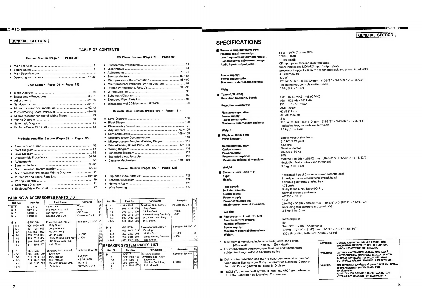
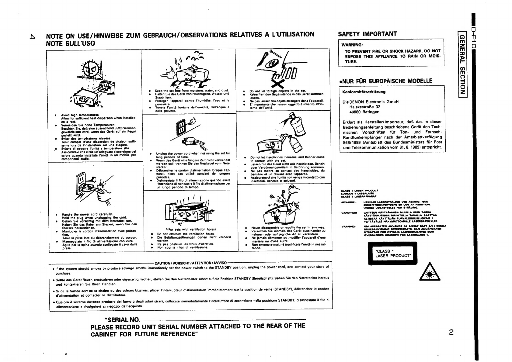
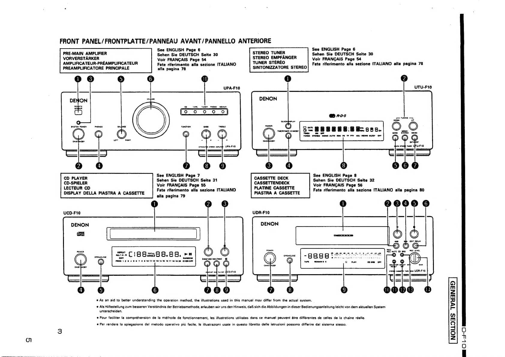
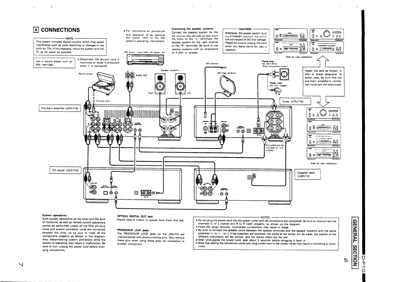
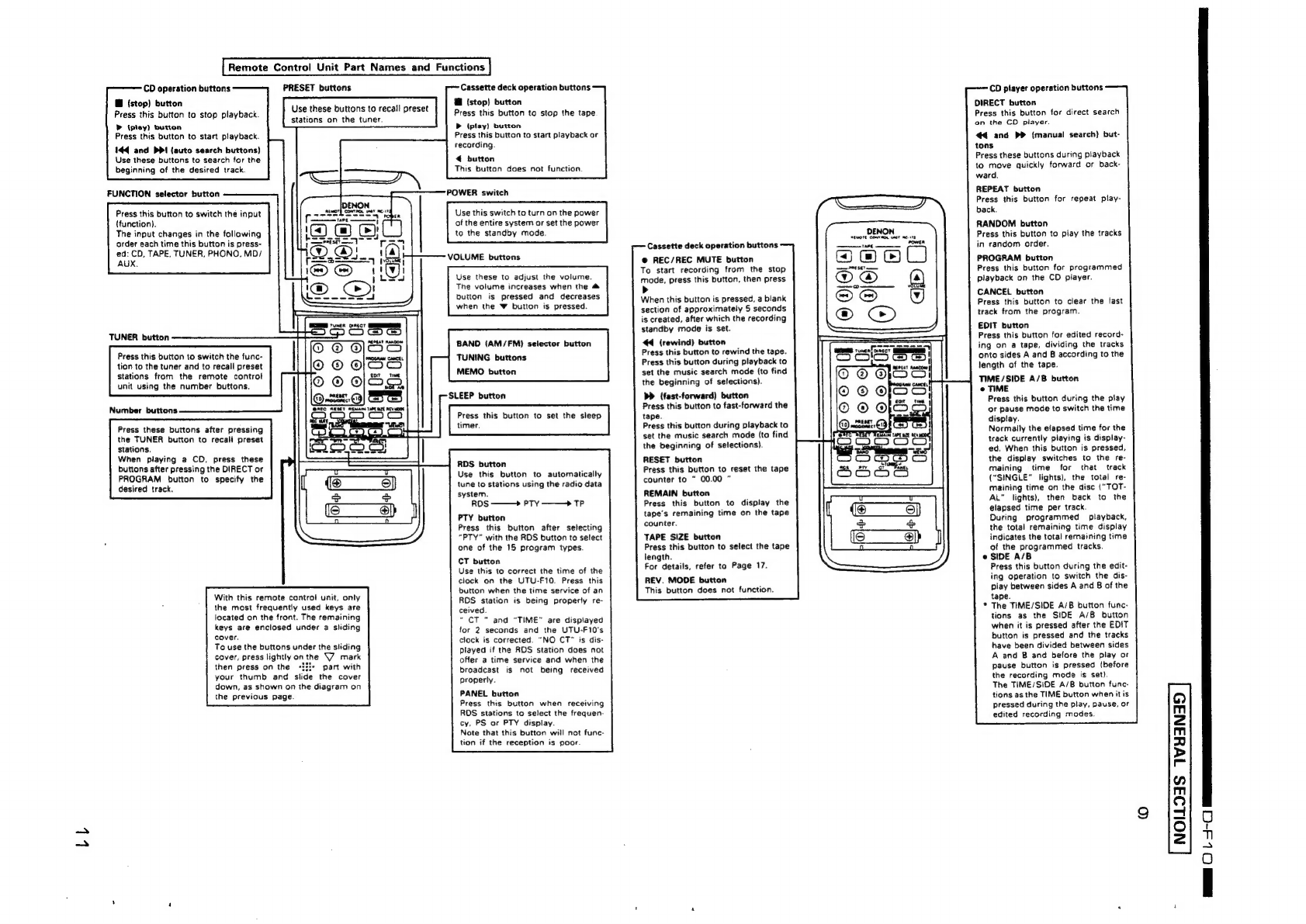
Denon D-F10 User manual

PERSONAL
COMPONENT
SYSTEM
D-F10
UNIT
No.
UTU-Fi0
(AM,
FIM
Stereo
Tuner)
UNIT
No.
UPA-F19°
(Pre-Main
Amplifier)
UNIT
No.
UCD-F10
(Compact
Disc
Player)
UNIT
No.
UDR-F19.
(Cassette
Tape
Deck)
RDS
compaiib’e
:
i
:
;
Compatible
with
various
RDS
services,
including
program
service
Two
timer
settings
can
be
made
—
everyday
and
sleep.
name
(PS},
program
type
identification
(PTY),
traffic
program
identi.
=
®
Easy-to-use
remote
control
unit
fication
(TP)
and
clock
time
(CT).
|
The
most
frequently
used
keys
are
located
on
the
front,
with
the
©
Quality
power
for
high
quality
sound
ie
remaining
keys
enclosed
under
a
sliding
cover.
:
55W
+
55W/
(3
chm
DIN)
high
quality
amplifier
and
termirais
for
large
.
-e
Auto
on
function
speukers.
oS
The
power
turns
on
automatically
and
playback
begins
when
the
play
e
digh
sound
qzality,
multi-function
CD
player
button
on
the
CD
player
or
the
cassette
deck
or
the
tuner
preset
B
=EATURES
DFAO
Edit
function
for
automatically
dividing
the
tracks
on
a
CD
for
recording
orie
sides
A
and
B
07
a
tape.
.S.L.C
for
piayback
with
high
quality
sound.
:
Cassette
deck
with
Dolby
B,
C
and
HX-Pro
circuits
For
playback
and
recording
of
high
quality
sound.
EFORE
USING
COMPACT
DIGITAL
AUDIO
e
The
D-F10
Personal
Component
Syste
cunsists
of
the
following:
An;
FM
Stereo
Tuner
Unit
Remote
Control
Unit
Soe
UTU-FIC
RC-172
Pre-Main
Amplifier
Unit
UPA-F10
CD
plaver
Unit.
UCD-F10
|
Casseite
Deck
Unit
UDR-F10
Two
types
of
timers
up/down
buttons
on
the
remote
control
unit
are
pressed.
Moving
the
system
e
Humming
may
be
produced
if
the
system
is
set
near
a
1V
set
or
other
To
prevent
short-circuiting
or
damage
of
connection
cords.
be
sure
to
audio
component
1
its
connection
cords.
If
this
heppens,
try
unplug
the
power
cord
and
disconnect
all
connection
cords
before
changing
the
position
of
the
equipment
and
connection
cords.
moving
the
system.
e
Do
not
move
the
system
abruptly
from
a
cold
place
tc
a
warm
place,
In
addition,
aiways
remove
CDs
before
moving
the
system.
if
not,
the
as
this
may
cause
dew
(water
droplets)
to
form
in
the
set,
preventing
CD
may
be
scratched.
c
proper
operation.
If
this
happens,
wait
one
hour
before
using
the
e
Before
turning
the
power
on
:
:
:
system.
/
Check
again
that
all
cdnnections
are
proper
and
thet
the
connection
=
=
°
Be
sure
to
keep
this
manual
1
e
UPA-F10
(pre-main
amplifier
unit)
|
e
Remote
control
unit
(RC-1-
)
4
e
System
connector
cable
...
oa
|
e
RGP/AA
batteries
....
2°
e
RCA
pin-piug
cord
4
e
Operating
instructions
..
e
AC
cord
.......
oe
*
UTU-Fi0
(AM/FM
stereo
funer}
e
Inst.
Sheet
...
1
e
FM
antenna
...........-.
e
UDR-F10
(cassette
tape
deck)
cords
are
not
damaged.
Always
set
the
power
switch
to
che
STANDBY
:
position
before
disconnecting
connection
cords.
Check
that
the
following
parts
are
included
in
th
e
AMioop
antenna
..
»
System
connector
cable
..
e
RCA
pin-plug
cord
.....
e
AC
cord
......
@
inst.
Sheet
..
|
N:
IPPON
COLUMBIA.
Co.,
LTD.
The
illustrations
used
in
this
manual
may
differ
from
the
actual
system.
e
package
aside
from
the
main
unit:
UCD-F10
(compact
cise
player)
e
System
cun:ectcr
cable
e
RCA
pin-plug
cord
..
e
Inst.
Sheet
.......-

SS
1
Car
TR
IT
iat
a
(FT
F
I
GENERAL
SECTION
|
TABLE
OF
CONTENTS
General
Section
(Page
1
~
Pages
28)
Main
Features
Before
Using
.
Main
Specifications
...
Operating
Instructions
Tuner
Section
(Pages
29
~
Pages
52)
Adjustments
..
Semiconductors
Wiring
Diagram
...
Schematic
Diagram
Block
Diagram
oo...
Disassembly
Procedures
Microprocessor
Documentation
Printed
Wiring
Board,
Parts
List
...
Microprocessor
Peripheral
Wiring
Diagram
Exploded
View,
Parts
List
Pre-Main
Amplifier
Section
(Pages
53
~
Pages
72)
Remote
Control
Unit
.
Block
Diagram
.
Level
Diagram
.
Adjustments
....
Semiconductor
Disassembly
Procedures
.
Microprocessor
Documentation
Microprocessor
Peripheral
Wiring
Diagram
Printed
Wiring
Board,
Parts
List
Wiring
Diagram
...sseseeecenees
Schematic
Diagram
....
Exploded
View,
Parts
List
CD
Player
Section
(Pages
73
~
Pages
$9)
Disassembly
Procedures
Laser
Pickup
..
Adjustments
..
Semiconductors
Microprocessor
Documentation
Microprocessor
Peripheral
Wiring
Diagram
Printed
Wiring
Board,
Parts
List
Wiring
Diagram...
Schematic
Diagram
Exploded
View,
Parts
List
Disassembly
of
CD
Mechanism
(FG-73)
...
Cassette
Deck
Section
(Pages
100
~
Pages
121)
e
Level
Diagram
.
100
e
Block
Diagram
.
100
«
Disassembly
Procedures
.
101
@
Adjustments
..........00
102~105
©
SEMICONGUCHOFS
.......ceeeeeeeeees
106~109
e
Microprocessor
Documentation
110
Microprocessor
Peripheral
Wiring
Diagram
111
@
Printed
Wiring
Board,
Parts
List
..............
112~115
e
Wiring
Diagram...
116
@
Schematic
Diagram
17
e
Exploded
View,
Parts
List
118
«
Cassette
Mechanism
......
119~121
Speaker
Section
(Pages
122
~
Pages
123)
Exploded
View,
Parts
List
.........-sesesssssssessseererseerseseenessencneenees
122
Schematic
Diagram
Network
Ass'y
Wire
Forming
.
PACKING
§
&
ACCESSORIES
PARTS
LIST
SPECIFICATIONS
@
Pre-main
amplifier
(UPA-F1
0)
Practical
maximum
output:
Low
frequency
adjustment
range:
High
frequency
adjustment
range:
GENERAL
SECTION
55
W
+55
W
(4
ohms
DIN)
100
Hz
+8
dB
10
kHz
+8
dB
Audio
input/output
jacks:
CD
input
jacks,
tape
input/output
jacks,
tuner
input
jacks,
MD/AUX
input/output
jacks,
processor
loop
jacks,
6.3mm
headphones
jack
and
phono
input
jacks
Power
supply:
AC
230
V,
50
Hz
Power
consumption:
130
W
Maximum
external
dimensions:
270
(W)
x
96
(H)
x
342(D)
mm_=(10-5/8"
x
3-25/32”
x
13-15/32")
{including
feet,
controls
and
terminals)
Weight:
4.5
kg
(9
Ibs.
15
02)
@
Tuner
(UTU-F10)
Reception
frequency
band:
FM:
87.50
MHZ—
108.00
MHZ
AM:
522
kHz-
1611
kHz
Reception
sensitivity:
FM:
1.51/75
ohms
AM:
20nV
FM
stereo
separation:
40
dB
(1
kHz)
Power
supply:
AC
230
V,
50
Hz
Power
consumption:
8W
Maximum
external
dimensions:
270
(W)
x
96
(H)
x
318(D)
mm_
=
(10-5/8"
x
3-25/32"
x
12-33/64")
{including
feet,
controls
and
terminals)
Weight:
2.8
kg
(6
Ibs.
3
oz)
@
CD
player
(UCD-F10)
Wow
&
flutter:
Below
measurable
limits
(+0.001%
W.
peak)
Sampling
frequency:
44.1
kHz
Optical
source:
Semiconductor
Power
supply:
AC
230
V,
50
Hz
Power
consumption:
8wW
Maximum
external
dimensions:
270
(W)
x
96
(H)
x
315(D)
mm
(10-5/8"
x
3-25/32"
x
12-13/32")
{including
feet,
controls
and
terminals)
Weight:
3.3
kg
(7
Ibs.
5
oz)
HH
Cassette
deck
(UDR-F10)
Type:
Horizontal
4-track
2-channel
stereo
cassette
deck
Heads:
1
hard
permalloy
recording/playback
head
1
double-gap
ferrite
erasing
head
Tape
speed:
4.75
cm/s
Included
circuits:
Dolby
B
and
C
NR,
Dolby
HX
Pro
Usable
tapes:
Normal,
chrome
and
metal
Power
supply:
AC
230
V,
50
Hz
Power
consumption:
13W
Maximum
external
dimensions:
Weight:
@
Remote
control
unit
(RC-172)
Remote
control
system:
Number
of
buttons:
Power
supply:
Maximum
externa!
dimensions:
270
(W)
x
96
(H)
x
313(D)
mm
(10-5/8”
x
3-25/32”
x
12-21/64")
{including
feet,
controls
and
terminals)
3.8
kg
(8
Ibs.
6
oz)
Infrared
pulse
50
Two
DC
1.5
V
R6P/AA
batteries
57
(W)
x
197
(H)
x
21(D)
mm
(2-1/4"
x
7-3/4"
x
53/64")
Ref.
No.
Part
No.
|
Part
Name
Remarks
_len
Ref.
No.
Part
No.
Part
Name
Remarks
@1
UTU
F10
Tuner
Unit
Tuner
hal
e
7
GEN
2742
Envelope
Sub.
Ass'y-3
included
UCD-F10|
1°
@2
UPA
F10
Pre-Main
Amp.
Unit
Amp
71
505
9125
009]
:Poly
Cover
@
3
UCDF10
CD
Player
Unit
CD
Player
ri,
7-2
203
2310
009)
2P
Pin
Cord
L=1000
€4
UDRF10
Casette
Deck
Unit
Cassette
Deck
|
1°
i
7-3
203
2315
004
Stereo
Minipiug
Cord
Ass’y
|
L=500
7-4
206
2108
003]
:AC
Conn.
with
Plug
a)
GEN
2740
Envelope
Sub.
Ass’y-1
included
UTU-F10|
16
7-5 511
2654
006)
inst.
Sheet
rp
5-1
505
9125
009}
Poly
Cover
(1)
5-2
231
1914
003)
Loop
Antenna
(a)
r
B
GEN
2744
Envelope
Sub.
Ass'y-4
included
UDR-F10}
15
5-3
395
0021
000
FM
Ant.
Ass'y
{1}
8-1
505
8006
019
Envelope
5-4
203
2310
009
2P
Pin
Cord
L=1000
(tH)
8-2
203
2223
002]
2P
Pin
Cord
L=1000
5-§
203
2315
004
Stereo
Minipiug
Cord
Ass'y
|
L=500
(1)
8-3
203
2315
004
Stereo
Miniptug
Cord
Ass'y
|
L=500
5-6
206
2108
003
:AC
Conn.
with
Plug
(1)
8-4
su
2651
009)
Inst.
Sheet
L
{5-7
511
2653
007
Inst.
Sheet
Mi;
SPEAKER
SYSTEM
PARTS
LIST
@6
GEN
2738
Envelope
Sub.
Ass'y-2
included
UPA-F10
a
Ref.
No.
Part
No.
Part
Name
Remarks
Oty
r
6-1
505
8006
019]
Envelope
HRs
+
ta
<
6-2
511
2614
004)
Inst.
Manuat
EGFIT
mil
©
5
pl
rere
SE
tie
Rus
Speaker
Systom
4.
6-3
511
2615
003|
Inst.
Manual
ESNLSPO
[(1)
3
eceigooaiil’
envelope
02
Pe
6-4
399
0235
005]
Remote
Control
Unit
RC-172
mi
Co
009
0107
007|
Out
Put
Cord
Ass'y
L=2000
(2)
/
6-5
=
Batteries
R6P/AA/UM-3
(2)
3
514
2644
003
Inst.
Manual
(ay
4
i
|
es
Weight:
130
g
(including
batteries)
(Approx.
4.6
02)
*
Maximum
dimensions
include
controls,
jacks,
and
covers.
(W)
=width,
(H)=height,
(D)
=
depth
ADVARSEL:
|
USYNLIG
LASERSTRALING
VED
ABNING,
NAR
.
spate
.
SIKKERHEDSAFBRYDERE
ER
UDE
AF
FUNKTION.
e
For
improvement
purposes,
specifications
and
functions
are
UNDGA
UDSAETTELSE
FOR
STRALING.
subject
to
change
without
advanced
notice.
Paes
VAROITUS!
—_LAITTEEN
KAYTTAMINEN
MUULLA
KUIN
TASSA
F
:
Fs
KAYTTOOHJEESSA
MAINITULLA
TAVALLA
SAATTAA
M
Dolby
noise
reduction
and
HX
Pro
headroom
extension
manufac-
ALTISTAA
KAYTTAJAN
TURVALLISUUSLUOKAN
1
tured
under
license
from
Dolby
Laboratories
Licensing
Corpora-
YUTTAVALLE
NAKYMATTOMALLE
LASERSATEILYLLE.
tion.
HX
Pro
originated
by
Bang
&
Olufsen.
VARNING-
OM
APPARATEN
ANVANDS
PA
ANNAT
SATT
AN
|
DENNA
BRUKSANVISNING
SPECIFICERATS,
KAN
@
“DOLBY”,
the
double-D
symbo!
Mand
“HX
PRO”
are
trademarks
SE
AGINELEN
mnATS
of
Doiby
Laboratories
Licensing
Corporation.
UTSATTAS
FOR
OSYNLIG
LASERSTRALNING
SOM
L.
OVERSKRIDER
GRANSEN
FOR
LASERKLASS
1.

{\
NOTE
ON
USE/HINWEISE
ZUM
GEBRAUCH/
OBSERVATIONS
RELATIVES
A
L’UTILISATION
NOTE
SULL’USO
SAFETY
IMPORTANT
@
Avoid
high
temperatures
Allow
for
sufficient
heat
dispersion
when
installed
on
a
rack,
e@
Vermeiden
Sie
hohe
Temperaturen
Beachten
Sie,
daG
eine
ausreichend
Luftzirkulation
gewahrleistet
wird,
wenn
das
Gert
auf
ein
Regal
gestellt
wird.
e@
£viter
des
températures
élavées
Tenir
compte
d‘une
dispersion
de
chaleur
suffi-
sante
lors
de
{installation
sur
une
étagére.
@
Evitate
di
esporre
i'unité
a
temperature
alte.
Assicuratevi
che
ci
sia
un’adeguata
dispersione
de!
calore
quando
instaliate
I’unita
in
un
mobile
per
componenti
audio.
uate”
sep
24
Keep
the
set
free
from
moisture,
water,
and
dust.
Halten
Sie
das
Gerat
von
Feuchtigkeit,
Wasser
und
Staub
fern.
Protéger
l'appareil
contre
I'humidité,
Ieau
et
la
poussiére.
Tenete
I'unita
jontana
dall‘umidita,
dall’acqua
e
datta
polvere.
Unplug
the
power
cord
when
not
using
the
set
for
long
periods
of
time.
Wenn
das
Gerat
eine
langere
Zeit
nicht
verwendet
werden
soll,
trennen
Sie
das
Netzkabel
vom
Netz-
stecker.
Débrancher
te
cordon
d’alimentation
forsque
|’ap-
pareil
n‘est
pas
utilisé
pendant
de
jongues
périodes.
Disinnestate
il
filo
di
alimentazione
quando
avete
lintenzione
di
non
usare
it
filo
di
alimentazione
per
un
lungo
periodo
di
tempo.
Do
not
let
foreign
objects
in
the
set.
Keine
fremden
Gegensténde
in
das
Gerat
kommen
lassen.
Ne
pas
laisser
des
objets
étrangers
dans
l'appareil.
£’
importante
che
nessun
oggetto
é
inserito
al!’in-
terno
dell’unita.
«
Do
not
let
insecticides,
benzene,
and
thinner
come
in
contact
with
the
set.
Lassen
Sie
das
Gerat
nicht
mit
Insektiziden,
Benzin
oder
Verdiinnungsmitteln
in
BerGhrung
kommen.
Ne
pas
mettre
en
contact
des
insecticides,
du
benzéne
et
un
diluant
avec
S‘appareil.
Assicuratevvi
che
Iunita
non
venga
in
contatto
con
insetticidi,
benzolo
o
solventi.
WARNING:
TO
PREVENT
FIRE
OR
SHOCK
HAZARD,
DO
NOT
EXPOSE
THIS
APPLIANCE
TO
RAIN
OR
MOIS-
TURE.
eNUR
FUR
EUROPAISCHE
MODELLE
Konformitatserkiarung
Die
DENON
Electronic
GmbH
HalskestraRe
32
40880
Ratingen
Erklart
als
Hersteller/Importeur,
da&
das
in
dieser
Bedienungsanleitung
beschriebene
Gerat
den
Tech-
nischen
Vorschriften
fir
Ton-
und
Fernseh-
Rundfunkempfanger
nach
der
Amtsbiattverfigung
868/1989
(Amtsbiatt
des
Bundesministers
fir
Post
und
Telekommunikation
vom
31.
8.
1989)
entspricht.
ADVARSEL:
USYNUG
LASERSTRALING
VED
ABienG.
NAR
SIKKERHEDSAPBRYDERE
ER
UDE
AF
FUNKTION.
UNOGA
UDSAETTELSE
FOR
STRALING.
Handle
the
power
cord
caretully.
VAROITUSI
LAITTEEN
KAYTTAMINEN
MUULLA
KUIN
TASSA
Hold
the
plug
when
unplugging
the
cord.
KAVTTOONJERSSA
MAINITULLA
TAVALLA
SAATTAA
e@
Gehen
Sie
vorsichtig
mit
dem
Netzkabel
um.
ALTISTAA
KAYTTAJAN
TURVALLISUUSLUOKAN
1
Halten
Sie
das
Kabe!
am
Stecker,
wenn
Sie
den
YUTTAVALLE
NAKYMATTOMALLE
LASERSATEN
VILLE.
Stecker
herausziehen,
“(For
sets
with
ventilation
holes)
Never
disassemble
or
modify
the
set
in
any
way.
VARNWNG-
OM
APPARATEN
ANVANDS
PA
ANNAT
SATT
AN
|
DENNA
@
Manipuler
te
cordon
d’alimentation
avec
précau-
tion,
:
Tenir
ta
prise
lors
du
débranchement
du
cordon.
@
Manneggiate
il
filo
di
slimentazione
con
cura.
Agite
per
la
spina
quando
scollegate
ii
cavo
dalla
presa.
purchase.
@
Sollte
das
Geraét
Rauch
produzieren
oder
eigenartig
riechen,
stellen
Sie
den
Netzschalter
sofort
auf
die
Position
STANDBY
(Bereitschaft),
ziehen
Sie
den
Netzstecker
heraus
und
kontaktieren
Sie
Ihren
Handler.
@
Si
de
la
furnée
sort
de
la
chaine
ou
des
odeurs
bizarres,
placer
I’interrupteur
d’alimentation
immeédiatement
sur
!a
position
de
veille
(STANDBY),
débrancher
le
cordon
d’alimentation
et
contacter
le
distributeur.
@
Qualora
it
sistema
dovesse
produrre
del
fumo
o
degli
odori
strani,
collocate
immediatamente
!‘interruttore
di
accensione
nella
posizione
STANDBY,
disinnestate
it
filo
di
alimentazione
e
rivoigetevi
al
negozio
dell’acquisto.
“SERIAL
NO.
Do
not
obstruct
the
ventilation
holes.
Die
Beldftungsdfinungen
dirfen
nicht
verdeckt
werden.
Ne
pas
obstruer
les
trous
d’aération.
Non
coprite
i
fori
di
ventilazione.
CAUTION
/
VORSICHT
/
ATTENTION
/
AVVISO
e
if
the
system
should
smoke
or
produce
strange
smells,
immediately
set
the
power
switch
to
the
STANDBY
position,
unplug
the
power
cord,
and
contact
your
store
of
Versuchen
Sie
niemals
das
Gerat
auseinander
zu
nehmen
oder
auf
jegliche
Art
zu
verandern.
Ne
jamais
démonter
ou
modifier
l'appareil
d'une
maniére
ou
d’une
autre.
Non
smontate
mai,
né
modificate
l'unita
in
nessun
modo.
PLEASE
RECORD
UNIT
SERIAL
NUMBER
ATTACHED
TO
THE
REAR
OF
THE
CABINET
FOR
FUTURE
REFERENCE”
BRUKSANVISMING
SPECIMCERATS.
KAN
ANVANDAREN
UTSATTAS
FOR
OSYNUG
LASERSTRALNING
SOM
OVERSKMIDER
GRANSEN
FOR
LASERKLASS
1.
“CLASS
1
LASER
PRODUCT"
q)
m
=a
m
a
>
-
2]
m
Q
=
fe)
a=
(SE
gm
NO
(_)
-j-C]
a

FRONT
PANEL/FRONTPLATTE/PANNEAU
AVANT/PANNELLO
ANTERIORE
See
ENGLISH
Page
6
See
ENGLISH
Page
6
PRE-MAIN
AMPLIFIER
Sehen
Sie
DEUTSCH
Seite
30
STEREO
TUNER
Sehen
Sie
DEUTSCH
Seite
30
VORVERSTARKER
Voir
FRANCAIS
Page
54
STEREO
EMPFANGER
Voir
FRANCAIS
Page
54
AMPLIFICATEUR-PREAMPLIFICATEUR
Fate
riferimento
alla
sezione
ITALIANO
TUNER
STEREO
Fate
riferimento
alla
sezione
{TALIANO
alla
pagina
78
PREAMPLIFICATORE
PRINCIPALE
alla
pagina
78
SINTONIZZATORE
STEREO
UPA-F10
DENON
po
ad
aH
ae
o
TAPE
TUNER
PHONO
=
MOVAUX
[oo
0
0
oO}
7
@ros
don
Syvattw
POWER
PHONES
or
FUNCTION
ene
TREQLE
TREE
IVTIMER
STANDBY
a
ol
Ge
hee
f
4
:
.
-
erresna
gy
atemso
wed
UPA-FI0
——
eo
a
re
—
—
_
—
See
ENGLISH
Page
7
See
ENGLISH
Page
8
CD
PLAYER
Sehen
Sie
DEUTSCH
Seite
31
CASSETTE
DECK
Sehen
Sie
DEUTSCH
Seite
32
omaha
Voir
FRANCAIS
Page
55
min
cabserie
Voir
FRANCAIS
Page
56
DISPLAY
DELLA
PIASTRA
A
CASSETTE
region
alla
sezione
ITALIANO
PIASTRA
A
CASSETTE
Fate
riferimento
alla
sezione
ITALIANO
alla
pagina
80
0
2000
O
UCD-F10
UDR-F10
om?
CIB
B2888.88.
>
sean
See
taS
a
a
tor
RANDOM
m: es
a
ued
PROO
12:3
48
6
7
OS
1611
12
12
14:18
16
17 10
19
28
OVER
OME
OMBTENDBY
e
As
an
aid
to
better
understanding
the
operation
method,
the
iltustrations
used
in
this
manual
may
differ
from
the
actual
system.
@
Als
Hilfestellung
zum
besseren
Verstandnis
der
Betriebsmethode,
erlauben
wir
uns
den
Hinweis,
da®
sich
die
Abbildungen
in
dieser
Bedienungsanleitung
leicht
von
dem
aktuellen
System
unterscheiden.
©
Pour
faciliter
ta
compréhension
de
la
méthode
de
fonctionnement,
les
iltustrations
utilisées
dans
ce
manuel
peuvent
étre
différentes
de
celles
de
ia
chaine
réelle.
©
Per
rendere
ta
spiegazione
del
metodo
operativo
piu
facile,
ie
ittustrazioni
usate
in
questo
libretto
delle
istruzioni
possono
differire
dal
sistema
stesso.
G)
m
=
m
wv
>
-
n
m
Q
=
°
=

[5]
PART
NAMES,
FUNCTIONS
AND
DISPLAYS
REMOTE SENSOR
When
operating
the
remote
control
unit,
point
it
at
this
sensor.
SYSTEM
POWER
switch
(This
turns
the
power
for
the
entire
system
on
and
off.)
Press
this
once
to
turn
the
power
on,
then
press
again
to
set
the
power
to
the
standby
mode.
Power
indicator
This
lights
when
the
power
cord
is
plugged
into
a
power
outlet,
and
flashes
for
5
seconds
after
the
system
power
is
turned
on.
PHONES
(headphones
jack}
Plug
the
headphones
into
this
jack.
No
sound
is
produced
from
the
speakers
when
headphones
are
plugged
in.
BALANCE
control
Use
this
to
adjust
the
balance
of
the
volume
between
the
left
and
right
channels.
When
set
at
the
center
position,
the
volume
is
the
same
for
the
left
and
right
channels.
CLOCK/DISPLAY
selector
button
This
button
is
used
to
switch
the
display
between
the
reception
frequency
and
the
clock.
TUNING
UP
and
DOWN
buttons
These
buttons
are
used
to
select
AM
and
FM
stations
and
to
set
the
clock
and
timer.
POWER
switch
Press
this
button
once
to
turn
the
tuner’s
power
on,
then
press
again
to
set
the
tuner
to
the
standby
mode.
in
the
standby
mode,
“OFF”
appears
on
the
display.
TIMER/
TIMER
STANDBY
button
Press
this
when
setting
the
timer
and
to
turn
the
timer
on
so
that
it
operates
at
the
set
times.
When
the
button
is
pressed
after
the
timer
has
been
set,
the
timer
standby
mark
("
(©
_
“)
appears
on
the
display.
Press
again
to
turn
the
mark
off.
The
timer
will
not
operate
when
the”
(&
”
mark
is
off.
©
VOLUME
control
Use
this
to
adjust
the
overall
volume.
The
volume
increases
when
the
control
is
turned
clockwise
(
}
and
decreases
when
it
is
turned
counterclockwise
(
()
).
FUNCTION
(input)
selector
button
Use
this
to
select
the
input
(function).
The
input
changes
in
the
following
order
each
time
this
button
is
pressed:
CD,
TAPE,
TUNER,
PHONO.
MD/AUX.
(The
function
changes
automatically
when
the
system’s
CD
player
or
cassette
deck
is
played
or
when
a
preset
channel
is
recatled
on
the
tuner.)
BASS
control
Use
this
to
adjust
the
volume
of
the
low
frequencies.
TREBLE
control
Use
this
to
adjust
the
volume
of
the
high
frequencies.
Function
indicators
These
light
to
indicate
the
currently
selected
function.
BAND
(AM/FM)
selector
button
The
band
switches
between
AM
and
FM
each
time
this
button
is
pressed.
MONO/STEREO
selector
button
AUTO
mode:
Use
this
mode
to
receive
programs
in
stereo.
The
sound
and
the
indicators
on
the
display
automatically
switch
between
monaural
(“MONO”)
and
stereo
(“STEREO”)
according
to
whether
the
program
is
being
broadcast
in
monau-
ral
or
stereo.
MONO
mode:
Use
this
mode
to
receive
programs
in
monaural,
regardless
of
whether
they
are
being
broadcast
in
monaural
or
stereo.
Set
this
mode
if
there
is
much
noise
or
if
the
signals
are
weak
when
receiving
stereo
programs
(when
“AUTO”
is
lit).
MEMO
ENT/NEXT
button
This
button
is
used
to
preset
AM
and
FM
stations
and
when
setting
the
timer.
Display
TUNER
DISPLAY
The
timer
will
ope-
rate
when
this
is
lit.
This
indicates
the
number
of
the
preset
channel.
This
lights
when
the
display
is
set
to
the
clock
mode.
:
The
reception
band,
reception
frequency,
time
and
timer
settings
are
displayed
here.
Displays
the
timer
and
RDS
data.
This
lights
when
a
station
is
tuned
in
properly.
This
flashes
for
approximately
10
seconds
when
the
MEMO
button
is
pressed
while
presetting
stations.
These
light
when
set-
ting
the
timer.
“TIMER”
lights
when
the
timer
is
set.
This
lights
when
the
sleep
timer
is
opera-
ting.
These
display
the
reception
mode.
STEREO:
This
lights
when
a
stereo
program
is
received
in
the
AUTO
mode.
:
This
lights
when
a
monaural
pro-
gram
is
received
in
the
AUTO
mode
and
when
the
MONO/STEREO
but-
ton
is
pressed,
setting
the
monaural
mode.
:
This
lights
when
the
MONO/STEREO
button
is
pressed,
setting
the
auto
mode.
This
lights
when
in
the
standby
mode.
MONO
AUTO
e@
RDS
(Radio
Data
System)
When
the
ROS
button
is
pressed,
a
station
is
searched
for
and
automatically
tuned
in,
the
“RDS”
indicator
lights
and
the
station's
name
is
displayed
on
the
frequency
display.
@
PTY
(Program
Type)
This
indicator
lights
when
the
type
of
RDS
program
is
specified.
e@
TP
(Traffic
Program)
received.
@
PS
(Program
Service
name)
This
lights
when
the
station
name
is
displayed.
NOTE:
©
The
timer
standby
mark
(”
©
“)
does
not
light
if
the
current
time
and
the
timer
have
not
been
set.
“TP”
lights
when
an
RDS
traffic
information
station
is
q)
m
2
mi
Ps)
>
-
2)
m
Q
=
)
2
Sa
aa
a
a
a
PS
()
|
1]
HER

CAUTION:
Whenever
the
power
switch
is
in
the
STANDBY
position.
the
unit
is
still
connected
on
AC
line
voltage
Please
be
sure
to
unplug
the
cord
when
you
leave
home
for,
say,
a
vacation.
[4]
CONNECTIONS
«For
instructions
on
connection
connecting
the
speaker
system
Connect
the
speaker
system
for
the
left
channel
{the
left
side
as
seen
from
NOTE:
MO
‘plaver.
fefer.t9-
the,
MD
the
front)
to
the “L”
terminals,
the
This
system
includes
digita!
circuitry
which
may
cause
player's
operating
instructions.
speaker
system
for
the
right
channel
interference
such
as
color
blotching
or
changes
in
the
to
the
“R”
terminals.
Be
sure
to
use
color
on
TVs.
If
this
happens,
move
the
system
and
the
speaker
systems
with
an
impedance
TV
as
far
apart
as
possible
MO
playe:.
video
deck.
LD
piayer,
etc
of
4
ohm
or
greater.
and
operation
of
an
optional
Side
by
side
instaliation
@
Disconnect
the
ground
cord
if
humming
or
noise
ts
produced
when
it
is
connected.
3
Power
piug
Use
a
record
player
with
an
FM
antenna
AC
230
V
50
Hz
(Plug
into
a
power
outlet.)
MM
cartridge
install
the
sets
as
shown
in
one
of
these
diagrams.
In
either
case,
be
sure
that
the
pre-main
amplifier's
ventila-
tion
holes
are
not
obstructed.
AM
loop
antenna
Record
player
AUDIO
OUT
,
Power
cord
{
{for
U.K.
model)
Pre-main
amplifier
(UPA-F10}
AC
outlets
are
not
included
on
U.K.
models.
Side
by
side
instailation
CD
player
(UCD-F10)
Cassette
deck
(UOR-F10)
System
operations
OPTICAL
DIGITAL
OUT
jack
Such
system
operations
as
the
timer
and
the
auto
Digital
data
is
output
in
optical
form
from
this
jack.
on
functions,
as
weil
as
remote
control
operations
cannot
be
performed
unless
ail
the
RCA
pin-plug
NOTES:
Do
not
plug
the
power
cord
into
the
power
outlet
until
all
connections
are
completed.
Be
sure
to
interconnect
the
channels
(L
to
L
(white)
and
R
to
R
{red))
properly,
as
shown
on
the
diagram.
e
Insert
the
plugs
securely.
incomplete
connections
may
result
in
noise.
cords
and
system
connector
cords
are
connected
PROCESSOR
LOOP
jacks
©
Be
sure
to
connect
the
speaker
cords
between
the
speaker
terminals
and
the
speaker
systems
with
the
same
between
the
units,
so
be
sure
to
make
all
the
The
PROCESSOR
LOOP
jacks
on
the
UPA-F10
are
polarities
(+
to
+,
-
to
-).
if
the
polarities
are
switched,
the
sound
at
the
center
will
be
weak,
the
position
of
the
connections
properly
as
shown
in
the
diagram.
interconnected
with
short-circuiting
pins.
Only
remove
different
instruments
will
De
unclear,
and
the
stereo
effect
will
be
fost.
,
'
Also,
disconnecting
system
connectors
while
the
these
pins
when
using
these
jacks
for
connection
to
©
After
unplugging
the
power
cord,
wait
about
5
seconds
before
piugging
it
back
in.
; ;
system
is
operating
may
result
in
malfunction.
Be
another
component.
e
Note
that
setting
the
connection
cords
(pin-plug
cords)
next
to
the
power
cords
may
result
in
humming
or
other
sure
to
turn
unplug
the
power
cord
before
chan-
Noise.
ging
connections.
NOILOSS
IWH4aNI9D
ea)
LR
Sp
a
r

Disc
tray
Load
discs
here.
>
(play)
button
Press
this
button
to
start
playing
the
disc.
Even
when
the
disc
tray
is
open,
the
disc
tray
closes
and
playback
begins
when
this
button
is
pressed.
When
pressed
in
the
standby
mode,
the
power
automatically
turns
on
and
playback
begins.
{Auto
on
function)
@
(stop)
button
Press
this
button
to
stop
playback.
POWER
switch
Press
this
once
to
turn
the
CO
player's
power
on,
then
press
again
to
set
the
CD
player
to
the
standby
mode.
in
the
standby
mode,
“OFF”
appears
on
the
display.
OPEN/CLOSE
button
Press
this
to
open
and
close
the
disc
tray.
When
oressed
once,
the
disc
tray
opens
out,
and
when
pressed
again,
the
disc
tray
closes.
If
a
disc
is
loaded,
the
totat
number
of
tracks
and
total
playing
time
of
the
disc
are
displayed
several
seconds
after
the
disc
tray
is
closed.
When
pressed
in
the
standby
mode,
the
CD
player's
power
turns
on.
Display
144
/
€4
(automatic
/
manual
search
reverse)
button
Use
this
to
move
to
the
beginning
of
a
specific
track.
When
pressed
during
playback
or
in
the
pause
mode,
the
pickup
moves
backward
a
number
of
tracks
equal
to
the
number
of
times
the
button
is
pressed.
D>
/
PPI
(automatic
/
manual
search
forward)
button
Use
this
to
move
to
the
beginning
of
a
specific
track.
When
pressed
during
playback
or
in
the
pause
mode,
the
pickup
moves
forward
a
number
of
tracks
equal
to
the
number
of
times
the
button
is
pressed.
@
The
automatic
search
mode
is
set
if
the
@
or
@
button
is
released
within
0.5
seconds,
and
the
manual
search
mode
is
set
if
the
button
is
held
for
over
0.5
seconds.
li(pause)
button
Press
this
button
to
stop
playback
temporarily.
Press
the
play
dutton
to
cancel
the
pause
mode
and
resume
playback.
The
following
is
displayed
on
the
track
number
display:
@
When
the
disc's
data
cannot
be
read
properly
*@
Inthe
stop
mode
.................
Totai
number
of
tracks
e
Inthe
play
and
program
modes
..
Track
number
@
When
the
innermost
or
outermost
section
of
the
disc
is
reached
during
the
>
(the
play
indicator)
manual
search
operation
............
CCor
3
lights
when
a
disc
is
The
following
is
displayed
on
the
time
display
:
@
When
the
disc’s
data
cannot
be
read
properly
...
ca cs
playing.and
lh:
(the
pause
indicator)
lights
when
the
pause
mode
is
set.
e
Inthe
stop
mode
«0...
@
Inthe
play
and
pause
modes
@
Inthe
program
mode
...........
..
Total
playing
time
Elapsed
time
for
current
track
Elapsed
time
of
programmed
tracks
Track
number
display
Time
display
This
lights
when
the
RANDOM
button
is
pressed.
LIBew8
6.88.
“PROG"
lights
during
program-
This
lights
if
there
are
more
med
playback.
than
20
tracks
on
the
disc.
Music
calendar
The
numbers
of
the
tracks
on
the
disc
are
displayed
here
(up
to
track
number
20).
The
number
for
the
corresponding
track
turns
off
after
that
track
is
played.
During
programmed
playback,
the
numbers
of
the
programmed
tracks
are
displayed
(up
to
track
number
20).
All
the
numbers
light
if
the
disc’s
data
cannot
be
read
properly.
This
lights
when
in
the
standby
mode.
During
the
editing
operation,
“EDIT”
lights,
“A“
is
displayed
on
the
track
display,
the
remaining
time
on
side
A
is
displayed
on
the
time
display,
and
the
numbers
of
the
tracks
to
be
recorded
on
side
A
light
on
the
music
calendar.
When
the
SIDE
A/B
button
is
pressed,
“B”
appears
on
the
track
number
display
and
the
remaining
time
for
side
B
is
displayed
in
the
same
way.
This
changes
as
follows
each
time
the
REPEAT
button
is
pressed:
1st
press:
REPEAT
1
(single-track
repeat)
is
displayed
and
the
number
of
the
track
to
be
repeated
on
the
music
calendar
lights.
2nd
press:
REPEAT
ALL
(al!-track
repeat)
is
displayed.
3rd
press:
REPEAT
A-
is
displayed.
4th
press:
REPEAT
A-B
is
displayed.
5th
press:
Nothing
is
displayed.
(Only
REPEAT
1
and
REPEAT
ALL
are
displayed
in
the
stop
mode.}
q@)
m
=
mi
a
>
-
2)
m
©)
=a
2)
2

=>
CASSETTE
DECK
Cassette
tray
The
cassette
tray
opens
out
when
the
OPEN/CLOSE
button
is
pressed.
Load
the
cassette
tape
with
the
side
on
which
the
tape
is
exposed
facing
away
from
you.
To
close
the
cassette
tray,
press
the
OPEN/
CLOSE
button
again.
For
details,
refer
to
Page
16.
44
(rewind)
button
Press
this
button
to
rewind
the
tape.
Press
this
button
during
playback
to
set
the
music
search
mode.
>
(plsy}
button
Press
this
button
to
start
playback.
When
pressed
in
the
standby
mode,
the
power
of
‘both
the
cassette
deck
and
the
pre-main
amplifier
turns
on
autornaticatly
and
playback
starts.
(Auto
on
function)
b>
(fast-forward)
button
Press
this
button
to
fast-forward
the
tape.
Press
this
button
during
playback
to
set
the
music
search
mode.
@
(stop)
button
Press
this
button
while
the
tape
is
moving
to
stop
the
tape.
EDIT
RELAY
button
The
cassette
tray
opens
when
all
the
tracks
for
side
A
of
the
tape
have
been
recorded
with
the
CD
edited
recording
function.
To
continue
recording
on
side
B,
turn
the
tape
over
then
press
this
button
to
close
the
cassette
tray
and
start
recording
POWER
switch
Press
this
once
to
turn
the
cassette
deck’s
power
on,
then
press
again
to
set
the
cassette
deck
to
the
standby
mode.
In
the
standby
mode,
“OFF”
appears
on
the
display.
OPEN/CLOSE
button
Press
this
to
open
and
close
the
cassette
tray.
When
pressed
in
the
standby
mode,
the
cassette
deck's
power
turns
on.
REC/REC
MUTE
button
This
button
is
used
when
recording
and
when
creating
blank
spaces
between
selections.
If
only
the
REC/REC
MUTE
button
is
pressed,
the
recording
pause
mode
is
set.
When
REC/REC
MUTE
button
is
pressed
while
in
the
recording
pause
mode,
the
recording
mute
mode
is
set
for
approximately
5
seconds.
creating
a
blank
space
on
the
tape,
after
which
the
recording
pause
mode
is
once
again
set.
When
the
>
(play)
button
is
pressed
while
in
the
recording
pause
mode,
record-
ing
begins.
The
recording
pause
mode
is
set
when
this
button
is
pressed
for
less
than
0.5
seconds
while
in
the
recording
mode.
If
it
is
pressed
for
over
0.5
seconds
while
in
the
recording
mode,
the
recording
mute
mode
is
set
for
approximately
5
seconds,
after
which
the
recording
pause
mode
is
once
again
set.
Press
the
@
(stop)
button
to
cancel
the
recording
pause
mode.
NOTE:
©
if
the
pfay
button
on
the
CD
player
is
pressed
during
the
recording
pause
mode,
recording
of
the
CD
begins
automatically.
COUNTER
RESET
button
Press
this
button
to
reset
the
tape
counter
to
“00.00
”.
DOLBY
NR
mode
selector
button
Use
this
to
select
the
Oolby
NR
mode
{OFF,
B
or
C).
When
piaying
a
tape,
set
the
Dolby
NR
mode
to
the
same
mode
as
when
the
tape
was
recorded.
CD-SRS
(Synchronized
Recording
System)
button
Use
this
button
for
synchronized
recording
of
CDs.
For
details,
refer
to
Page
19.
REC
LEVEL
control
Use
this
to
set
the
recording
level.
[6]
REMOTE
CONTROL
UNIT
inserting
the
batteries
NOTES:
*
Use
R6P
(AA)
batteries
in
this
remote
contro!
unit.
*
Replace
the
batteries
with
new
ones
approximately
once
each
year,
though
this
depends
on
how
fre-
quently
the
remote
control
unit
is
used.
e
Replace
the
batteries
with
new
ones
earlier
if
the
remote
contro!
unit
does
not
operate
even
from
a
short
distance.
e
Insert
the
batteries
in
the
proper
+
and
~
direction,
following
the
marks
in
the
battery
compartment.
e
Remove
the
batteries
when
not
using
the
remote
control
unit
for
extended
periods
of
time.
©
To
avoid
damage
and
leakage:
Do
not
use
a
new
battery
with
an
old
one.
-
Do
not
use
two
different
types
of
batteries.
-
Do
not
short-circuit,
take
apart,
heat
or
dispose
of
batteries
in
flames.
©
If
the
batteries
should
leak,
carefully
wipe
the
fluid
out
of
the
battery
compartment,
then
insert
new
batteries.
@
Remove
the
remote
control
unit's
sliding
cover.
@
Insert
the
two
R6P
(AA)
batteries,
following
the
+
and
-
marks
in
the
battery
compartment.
thumb
and
slide
off.
G@)
m
=
mi
Ps]
>
-
wn
m
if)
a
)
2
For
details,
refer
to
Page
19.
Cautions
on
U:
@
The
remote
control
unit
may
not
operate
if
the
remote
sensor
is
exposed
to
direct
sunlight
or
the
strong
light
from
a
lighting
fixture,
or
if
there
is
an
obstacle
between
the
remote
contro!
unit
and
the
remote
sensor.
e
Do
not
press
buttons
on
the
remote
control
unit
and
on
the
set
at
the
same
time.
Doing
so
could
result
in
malfunction.
©
Display
If
the
remote
contro!
unit
is
pointed
away
from
the
remote
sensor
during
continuous
operations
(such
as
when
turning
the
volume
up
or
down),
the
operation
will
stop.
If
this
happens,
point
the
remote
contro!
unit
at
the
remote
sensor
and
press
the
but
ton
again.
CASSETTE
DECK
DISPLAY
This
displays
the
tape
counter
and
tape
size.
This
displays
the
record-
ing
and
playback
level.
o>
+40
-30
-20 -18
8-3-4
Oo
43
OB
10
a
5
ai
a
5
tL
cOoncooRoonRAAoORoaSsooAaD
R
DOOOCoOoOoONMODOOcoSaESHoaDpoDATM
TAPE
—-REMAIN.B
_C!
e
The
remote
sensor
is
located
on
the
pre-main
amplifier.
Point
the
remote
control
unit
at
the
remote
sensor
as
shown
on
the
diagram
when
operating
it.
The
remote
contro!
unit
will
operate
from
a
direct
distance
of
approximately
7
meters,
but
this
distance
will
be
shor-
tened
if
obstacles
are
present
or
if
operated
at
an
angle.
(The
remote
control
unit
will
operate
at
an
angle
of
up
to
30°
in
either
direction.)
CO
SRS
OFF
This
lights
when
the
tape
counter
is
set
to
the
re-
maining
time
mode.
This
lights
during
re-
cording.
This
lights
when
in
the
standby
mode.
This
fights
during
syn-
chronized
recording
of
a
co.
These
indicate
the
Dolby
NR
mode.
This
lights
during
play-
back
and
record.
This
indicates
whether
or
not
a
tape
is
toaded.
This
is
not
displayed
when
no
cassette
tape
is
loaded
in
the
cassette
tray.
oo
8
e
SS
OI
IT
TENE
EI
MRCS
()
|
—\-(]
SSR

LL
CD
operation
buttons
@
(stop)
button
Press
this
button
to
stop
playback.
»
{play}
button
Press
this
button
to
start
playback.
144
and
PPI
(auto
search
buttons)
Use
these
buttons
to
search
for
the
beginning
of
the
desired
track.
PRESET
buttons
Use
these
buttons
to
recall
preset
stations
on
the
tuner.
Cassette
deck
operation
buttons
@
(stop)
button
Press
this
button
to
stop
the
tape
D>
iplay)
button
Press
this
button
to
start
playback
or
recording.
@
button
This
button
does
not
function.
FUNCTION
selector
button
POWER
switch
Press
this
button
to
switch
the
input
(function).
The
input
changes
in
the
following
order
each
time
this
button
is
press-
ed:
CD,
TAPE,
TUNER,
PHONO,
MD/
AUX.
Use
this
switch
to
turn
on
the
power
of
the
entire
system
or
set
the
power
to
the
standby
mode.
VOLUME
buttons
Use
these
to
adjust
the
volume.
The
volume
increases
when
the
&
button
is
pressed
and
decreases
when
the
W
button
is
pressed.
TUNER
button
BAND
(AM/FM}
selector
button
Press
this
button
to
switch
the
func-
TUNING
buttons
tion
to
the
tuner
and
to
recall
preset
stations
from
the
remote
controt
MEMO
button
unit
using
the
number
buttons.
SLEEP
button
Number
buttons
Press
this
button
to
set
the
sleep
Press
these
buttons
after
pressing
the
TUNER
button
to
recall
preset
stations,
When
playing
a
CD.
press
these
buttons
after
pressing
the
DIRECT
or
PROGRAM
button
to
specify
the
desired
track.
RDS
button
Use
this
button
to
automatically
tune
to
stations
using
the
radio
data
system.
ROS
——
PTY
———>
TP
PTY
button
Press
this
button
after
selecting
“PTY”
with
the
RDS
button
to
select
one
of
the
15
program
types.
CT
button
Use
this
to
correct
the
time
of
the
clock
on
the
UTU-F10.
Press
this
button
when
the
time
service
of
an
RDS
station
is
being
properly
re-
ceived.
“
CT
"
and
“TIME”
are
displayed
for
2
seconds
and
the
UTU-F10's
clock
is
corrected.
“NO
CT"
is
dis-
played
if
the
RDS
station
does
not
offer
a
time
service
and
when
the
broadcast
is
not
being
received
property.
PANEL
button
Press
this
button
when
receiving
RDS
stations
to
select
the
frequen-
cy,
PS
or
PTY
display.
Note
that
this
button
will
not
func-
tion
if
the
reception
is
poor
With
this
remote
control
unit,
only
the
most
frequently
used
keys
are
located
on
the
front.
The
remaining
keys
are
enclosed
under
a
sliding
cover.
To
use
the
buttons
under
the
sliding
cover,
press
lightly
on
the
\7
mark
then
press
on
the
*
part
with
your
thumb
and
s
the
cover
down,
as
shown
on
the
diagram
on
the
previous
page.
Cassette
deck
operation
buttons
@
REC/REC
MUTE
button
To
start
recording
from
the
stop
mode,
press
this
button,
then
press
»
When
this
button
is
pressed,
a
blank
section
of
approximately
5
seconds
is
created,
after
which
the
recording
standby
mode
is
set.
44
(rewind)
button
Press
this
button
to
rewind
the
tape.
Press
this
button
during
playback
to
set
the
music
search
mode
(to
find
the
beginning
of
selections).
D>
(fast-forward)
button
Press
this
button
to
fast-forward
the
tape.
Press
this
button
during
playback
to
set
the
music
search
mode
(to
find
the
beginning
of
selections).
RESET
button
Press
this
button
to
reset
the
tape
counter
to
“
00.00
”
REMAIN
button
Press
this
button
to
display
the
tape’s
remaining
time
on
the
tape
counter.
TAPE
SIZE
button
Press
this
button
to
select
the
tape
length.
For
details,
refer
to
Page
17.
REV.
MODE
button
This
button
does
not
function.
SEWOTE
CONTRO
UNIT
RCI?
Powe!
aera
CD
ptayer
operation
buttons
DIRECT
button
Press
this
button
for
direct
search
on
the
CD
player.
44
and
D>
(manual
search)
but-
tons
Press
these
buttons
during
playback
to
move
quickly
forward
or
back-
ward.
REPEAT
button
Press
this
button
for
repeat
play-
back.
RANDOM
button
Press
this
button
to
piay
the
tracks
in
random
order.
PROGRAM
button
Press
this
button
for
programmed
playback
on
the
CD
player.
CANCEL
button
Press
this
button
to
clear
the
last
track
from
the
program.
EDIT
button
Press
this
button
for
edited
record-
ing
on
a
tape,
dividing
the
tracks
onto
sides
A
and
B
according
to
the
length
of
the
tape.
TIME/SIDE
A/B
button
o
TIME
Press
this
button
during
the
play
or
pause
mode
to
switch
the
time
display.
Normaily
the
elapsed
time
for
the
track
currently
playing
is
display-
ed,
When
this
button
is
pressed,
the
display
switches
to
the
re-
maining
time
for
that
track
("SINGLE”
lights),
the
total
re-
maining
time
on
the
disc
(“TOT-
AL”
lights),
then
back
to
the
elapsed
time
per
track.
During
programmed
playback,
the
total
remaining
time
display
indicates
the
total
remaining
time
of
the
programmed
tracks.
SIDE
A/B
Press
this
button
during
the
edit-
ing
operation
to
switch
the
dis-
play
between
sides
A
and
B
of
the
tape.
The
TIME/SIDE
A/B
button
func-
tions
as
the
SIDE
A/B
button
when
it
is
pressed
after
the
EDIT
button
is
pressed
and
the
tracks
have
been
divided
between
sides
A
and
B
and
before
the
play
or
pause
button
is
pressed
(before
the
recording
mode
is
set).
The
TIME/SIDE
A/B
button
func-
tions
as
the
TIME
button
when
it
is
pressed
during
the
play,
pause,
or
edited
recording
modes.
*
G)
m
2
mi
P
>
~
”
m
'?)
=
°
2

LISTENING
TO
RADIO
PROGRAMS
(Check
the
connections
on
Pages
4
and
5.}
Tunes
(UTU-F10)
Example:
Tuning
in
FM
87.50
MHz
(AM
stations
are
tuned
in
using
the
same
procedure.)
Set
the
VOLUME
control
on
the
pre-main
amplifier
to
the
minimum
position,
then
press
the
SYSTEM
POWER
switch
to
turn
on
the
power
SYSTEM
POWER
Press
the
BAND
button
on
the
tuner
to
select
the
FM
band,
Use
the
TUNING
UP
and
DOWN
buttons
to
tune
the
frequency
to
87.50.
Once
the
EM
frequency
is
tuned
in,
adjust
:
a
the
volume
to
the
desired
level
using
the
VOLUME
control.
ro
This
lights
when
a
station
is
tuned
in.
B7.So.
re
sim
Auto
Tuning
When
one
of
the
TUNING
buttons
is
pressed,
the
frequency
changes
in
steps
of
50kHz
in
the
FM
band,
9kHz
in
the
AM
band.
@
If
one
of
the
TUNING
buttons
is
held
in
for
over
1
second,
the
frequency
continues
to
change
when
the
button
is
released
{auto
tuning)
and
stops
when
a
station
is
tuned
in.
Tuning
will
not
stop
at
stations
whose
reception
is
poor.
@
To
stop
the
auto
tuning
function,
press
the
UP
or
DOWN
button
once.
Example:
Presetting
FM
87.50
(currently
tuned
in)
at
preset
number
3
Flashes
Press
the
MEMO
ENT/NEXT
button
pad
BUS
ooo
%
1.23
Sane
eas
be
S
The
indicator
flashes
for
Sy
ENTINEXT
ara
10
seconds.
Use
the
UP
and
DOWN
buttons
to
call
out
the
mumber
at
which
you
want
to
preset
the
station
(3),
or
simply
press
the
corresponding
number
button
@
on
the
remote
contro!
unit.
Flashes
“P3"
fights
B%.
Press
the
MEMO
ENT/NEXT
button
while
the
indicator
is
flashing.
O.P
3
Up
to
30
AM
or
FM
stations
can
be
preset
using
this
procedure.
NOTES:
@
In
addition
to
the
reception
frequency,
the
reception
mode
{monaural
or
auto}
is
also
preset,
so
check
the
display
when
Ppresetting
stations.
®
If
a
station
is
preset
at
a
number
where
a
station
is
already
preset,
the
previous
station
is
replaced
with
the
new
station.
e
The
preset
memory
is
not
cleared
immediately
when
the
power
cord
is
unplugged,
but
is
cleared
if
the
cord
is
left
4
Oo
unplugged
for
an
extended
period
of
time.
If
this
happens,
preset
the
stations
again.
Listening
to
Preset
Stations
The
preset
stations
can
be
recalled
using
the
number
buttons
on
the
remote
control
unit.
Also,
if
the
following
operation
is
performed
when
the
system
power
is
off,
the
power
automatically
turns
on
and
the
radio
is
played.
{Auto
on
function)
Example:
Listening
to
the
station
preset
at
number
3
{This
operation
is
only
possible
from
the
remote
contro!
unit.)
Press
the
TUNER
button
on
the
remote
control
unit.
B87.S56G..P
3.
Press
button
“3”
on
the
remote
control
unit.
Using
the
RDS
functions
Receiving
RDS
broadcasts
(FM
only)
Press
the
BAND
button
and
set
the
FM
band.
Press
the
ROS
button
once.
Fiashes
“RDS”
blinks
Press
the
AUTO
TUNING
UP
or
DOWN
button.
MY
“TUNING:
“RDS”
displayed
The
station
is
tuned
in.
“RDS”
lights
ater
5
seconds
of
flashing
Once
the
station
is
tuned
in,
“ROS”
flashes
for
5
seconds
and
the
program
service
name
is
displayed.
NOTE:
If
no
RDS
station
is
found,
“NQ
PROG”
is
displayed.
Q
m
2
m
a
>
-
”
m
.?)
=
fe)
2
A
NEE
SSD,
()
|
—|-)
S

Eb
m
t3
3}
Cl];
Ut
ea
“oll
2
z3yciyn
-4)/
Oy
C3
3a
{|m]|
-4
ot
rT
||
cz
ralfem
ite
m]|
-4
zz
|]
cz
||
D
r3||
Ol
=e
myim
PTY
Search
Press
the
RDS
button
twice
Press
the
PTY
button
to
select
the
type
of
program.
(One
of
the
15
types
listed
below
can
be
selected.)
Press
the
AUTO
TUNING
UP
or
DOWN
button.
The
station
is
tuned
in.
NOTE:
If
no
program
of
the
specified
type
is
found,
“0
PROG”
is
displayed
Programs
{News}
7 ‘
mM
—
se
u1
(Current
Affairs)
3B
n n
xB
4
3
ut
(Information)
(Sport)
(Education}
wy
(Drama)
(Culture)
{Science}
Flashes
{"PTY”
and
“ROS”
flash,
and
“—PTY~"
is
displayed.)
Flashes
“PTY”
and
“ROS”
light
after
5
seconds
of
flashing
Once
the
station
is
tuned
in,
“RDS”
and
“PTY”
flash
for
5
seconds
and
the
program
service
name
is
displayed.
(Varied)
(Pop
Music)
(Rock
Music)
{M.O.R.
Music)
(Light
Classics)
(Serious
Classics)
Hi
4
H
—
fe
M
{Other
Music)
TP
Search
Press
the
RDS
button
3
times.
Press
the
UP
or
DOWN
button
of
AUTO
TUNING.
Flashes
TP"
and
“RDS”
fight
Broadcast
reception.
Once
the
station
is
tuned
in,
“TP”
and
“RDS”
tight
and
the
program
service
name
is
dispiayed.
NOTE:
"*t0
PROG
”
is
displayed
when
there
is
no
traffic
information
broadcast
station.
Receiving
FM
programs
in
stereo
@
Press
the
MONO/STEREO
button
to
turn
on
the
“AUTO”
indicator.
When
a
program
being
broadcast
in
stereo
is
received,
the
“STEREO”
indicator
lights
and
the
program
is
received
in
stereo.
e
If
reception
is
poor
and
there
is
much
noise
in
the
stereo
signals,
press
the
MONO/STEREO
button
to
set
the
monaural
mode.
NOTE:
@
A
humming
sound
may
be
heard
when
using
a
TV
nearby
while
receiving
AM
programs.
If
this
happens,
move
the
system
as
far
from
the
TV
as
possible.
q)
m
=
mi
wv
>
re
”
m
?)
=
o
=

i
USING
THE
TIMER
The
time
and
timer
functions
are
incorporated
in
the
tuner.
@Types
of
timer
operations
TIMER
:
Use
this
to
turn
the
power
on
and
off
at
the
same
times
every
day.
SLEEP TIMER
Use
this
to
set
the
power
to
turn
off
after
10
to
60
minutes,
in
steps
of
10
minutes
(operated
from
the
remote
control
unit).
W
Notes
on
timer
settings
@
Be
sure
to
set
the
current
time
beforehand.
@
To
listen
to
or
record
a
radio
program
(“air
check”)
using
the
timer,
be
sure
to
preset
the
station
beforehand.
(Refer
to
“Presetting
AM
and
FM
Stations”
on
Page
10.)
Should
there
be
a
power
failure
or
should
the
power
cord
be
unplugged,
the
time
display
will
flash
at
"
00:00
“.
If
this
happens,
reset
the
current
time.
Also
check
the
timer
and
tuner
presettings,
and
reset
them
if
they
have been
cleared.
To
check
the
tirner
settings,
press
the
TIMER/
TIMER
STANDBY
button
for
at
least
3
seconds.
(This
can
also
be
done
when
the
tuner's
power
is
off.)
Next,
press
the
ENTER/NEXT
button
repeatedly
to
display
the
timer
start
mode,
the
reception
band
and
preset
channel
number
when
in
the
tuner
mode,
the
on
time
and
the
off
time.
Press
the
ENTER/NEXT
button
once
more
to
return
to
the
current
mode
display.
Changing
the
Settings
Repeat
the
timer
setting
operation
to
erase
the
previous
settings
and
set
the
new
settings.
Clearing
the
Settings
Press
the
TIMER/TIMER
STANDBY
button
for
at
least
3
seconds,
then
press
it
again
while
“FUNC”
is
displayed
to
clear
the
timer
settings.
Note
on
Setting
the
Timer
If
the
time
set
with
the
timer
is
reached
while
the
system
power
is
on,
the
operation
switches
to
the
operation
set
by
the
timer.
Turning
the
Timer
Off
Press
the
TIMER/TIMER
STANDBY
button
to
turn
the
©
mark
off.
12
Tuner
({UTU-F10}
60
B7.SG.peas.
Press
the
CLOCK/DISPLAY
button
for
at
least
3
seconds.
Use
the
UP
and
DOWN
buttons
to
set
the
hours.
Press
the
MEMO
ENT/NEXT
button.
Use
the
UP
and
DOWN
buttons
to
set
the
minutes.
Press
the
MEMO
ENT/NEXT
button
at
the
sound
of
a
time
service's
chime,
The
time
display
stops
flashing
and
the
clock
starts
running.
e
The
current
time
can
be
set
even
when
the
power
is
off.
@
If
an
RDS
station
offers
a
time
service,
the
time
can
be
set
by
pressing
the
CT
button
on
the
remote
control
unit
while
that
Station
is
tuned
in.
Lie
G
0
The
hours
place
flashes.
(If
the
hours
have
already
been
set,
that
number
flashes.}
Meena
7
[np
bs bs
The
hours
place
flashes.
ahaa
The
minutes
place
flashes.
Ak
{If
the
minutes
have
already
been
set,
that
number
flashes.)
1
Gg
“rhe
The
minutes
place
flashes.
t
.
NON
{
G
.
34
tT?
The
display
stops
flashing
and
Le
e
the
clock
starts
running
from
00
seconds.
NOILOAS
TWHAINID

The
power
can
be
set
to
turn
on
and
off
every
day
at
the
same
time
in
any
of
five
modes:
tuner,
CD,
cassette
deck,
MD
player
(optional)
and
air
check
(recording
from
the
radio).
(Preset
the
AM
or
FM
station
beforehand.)
Tuner
(UTU-F10}
O)
mace]
Oss
F
m
TIMER/TIMER
STANOBY
button
B1.5S..
name
qrUue
emme
ao
aS
ew
rT
ue
ene
mY
or
MEMO
ENT/NEXT
button
UP
and
DOWN
buttons
Example:
Setting
the
tuner
to
turn
on
at
12:35,
off
at
12:56
{with
FM
87.50
MHz
preset
at
channel
“3”}
Press
the
SYSTEM
POWER
switch
‘on
the
pre-main
amplifier
to
turn
on
the
system's
power.
Press
the
TIMER/TIMER
STANDBY
button
for
at
least
3
secands
to
set
the
timer
setting
mode.
Use
the
UP
and
OOWN
buttons
to
set
the
“TUNER”
mode.
Use
the
UP
and
DOWN
buttons
to
set
the
preset
channel!
number.
Press
the
MEMO
ENT/NEXT
button.
Use
the
UP
and
DOWN
buttons
to
set
the
hours
for
the
timer
on
time.
Press
the
MEMO
ENT/NEXT
button]
|
SYSTEM
POWER
TIMER/TIMER
STANOBY
Say
that
FM
90.00
MHz
is
tuned
in
at
preset
channel
number
“1”
TUNER
Flashes
uf
the
timer
has
aiready
been
set.
that
number
flashes.)
Flashes
Flashes
ENTNEXT
®;
Press
the
MEMO
ENT/NEXT
button.
Use
the
UP
and
DOWN
buttons
to
set
the
minutes
for
the
timer
on
time.
Press
the
MEMO
ENT/NEXT
button.
Use
the
UP
and
DOWN
buttons
to
set
the
hours
for
the
timer
off
time.
Press
the
MEMO
ENT/NEXT
button.
Use
the
UP
and
DOWN
buttons
to
set
the
minutes
for
the
timer
off
time.
Press
the
MEMO
ENT/NEXT
button.
ENTNEXT
3
TMEA/TIMER
STANDBY
Press
the
TIMER/TIMER
STANDBY
button.
SYSTEM
POWER
Press
the
SYSTEM
POWER
switch
on
the
pre-main
amplifier
to
turn
off
the
system's
power.
NOTES:
the
TIMER/TIMER
STANDBY
button.
Flashes
tf
the
timer
has
already
been
set,
that
number
flashes.)
Flashes
Flashes
(if
the
timer
has
already
been
set,
that
number
flashes.)
Flashes
{if
the
timer
has
already
been
set,
that
number
flashes.)
nan
U3.
LS
ee
P
The
display
returns
to
as
it
was
before
the
timer
setting
mode
was
set.
tthe
©
markis
displayed
after
the
TIMER/
TIMER
STANDBY
button
is
pressed,
the
timer
will
operate
at
the
same
times
every
day.
To
turn
the
timer
off,
press
the
TIMER/TIMER
STANDBY
button
again
to
turn
the
mark
off..
e@
The
standby
mark
(“
©
“will
not
light
if
the
current
time
is
not
set.
if
this
is
the
case,
set
the
current
time,
then
press
*
When
an
optional
mini-disc
(MO)
player
is
connected,
it
can
be
operated
with
the
timer.
For
instructions,
refer
to
the
MD
player’s
operating
instructions.
q)
m
=
m
PS)
>
re
”
m
i?)
=
2)
=

Various
Timer
Operations
Pre-main
amplifier
(UPA-F10)
Pre-main
amplifier
(UPA-F10}
OL
CD
player
(UCD-F10)
Cassette
deck
(UDR-F10)}
G)
m
2
m
a
>
-
”
m
i?)
=
io)
a
=v.
C18B=88.88.
os
=888866:6
8-580.
Exampie
2:
Playing
a
cassette
tape
with
the
timer
SYSTEM
POWER
Press
the
SYSTEM
POWER
switch
on
the
pre-main
amplifier
to
turn
on
the
system's
power.
Press
the
cassette
deck’s
OPEN/
Srencaoet
CLOSE
button
to
open
the
cassette
tray.
Load
the
cassette
tape
in
the
cassette
tray.
Refer
to
Page
16.
Press
the
SYSTEM
POWER
switch
on
the
pre-main
amplifier
to
turn
on
the
system’s
power.
Press
the
CD
player's
OPEN/CLOSE
button
to
open
the
disc
tray.
Load
the
disc
in
the
disc
tray.
Refer
to
Page
20.
Press
the
CD
player's
OPEN/CLOSE
button
again
to
close
the
disc
tray.
OPEwCLOsE
Press
the
cassette
deck’s
OPEN/
CLOSE
button
again
to
close
the
cassette
tray.
TIMERTHMER
STANDBY
CY
Press
the
tuner’s
TIMER/TIMER
5
|
STANDBY
button
for
at
least
3
seconds.
Press
the
tuner’s
TIMER/TIMER
Oe
pee
ee
STANDBY
button
for
at
least
3
seconds.
Use
the
tuner’s
UP
and
DOWN
buttons
to
set
the
“CD”
mode.
Use
the
tuner’s
UP
and
DOWN
buttons
to
set
the
“TAPE”
mode.
Now
follow
steps
6
to
16
under
“Setting
the
Timer”
on
Page
13.
®
Check
that
the
cassette
deck
is
set
to
the
desired
Dolby
NR
mode.
14

Lb
Pre-main
amplifier
(UPA-F10}
Cassette
deck
(UDR-F10)
Press
the
SYSTEM
POWER
switch
on
the
pre-main
amplifier
to
turn
on
the
system’s
power.
Press
the
cassette
deck’s
OPEN/
CLOSE
button
to
open
the
cassette
tray.
Load
the
cassette
tape
in
the
3
|
cassette
tray.
Refer
to
Page
16.
OPEN/CLOSE
Press
the
cassette
deck’'s
OPEN/
CLOSE
button
again
to
close
the
cassette
tray.
TMERVTIMER
STANOBY
Sy
po
TUNING
—
OWN
uP
C
O
_.
AERCH
Now
foliow
steps
4
to
16
under
“Setting
the
Timer”
on
Page
13.
Press
the
tuner’s
TIMER/TIMER
STANDBY
button
for
at
least
3
seconds.
6
Use
the
tuner’s
UP
and
DOWN
buttons
to
set
the
“AIRCH”
mode.
Recording
is
not
possible
on
the
leader
tape
at
the
beginning
of
the
cassette
tape,
so
to
avoid
missing
any
of
the
program,
we
recommend
setting
the
timer
to
approximately
1
minute
before
the
program
is
scheduled
to
start.
@
When
an
optional
mini-disc
(MD)
player
is
connected,
radio
programs
can
be
recorded
using
the
timer.
For
instructions,
refer
to
the
MOD
player's
operating
instructions.
With
this
function,
the
power
can
be
set
to
turn
off
after
10
to
60
minutes,
in
steps
of
10
minutes,
using
the
remote
control
unit.
Exemple:
Setting
the
power
to
turn
off
in
50
minutes
{This
operation
is
only
possible
from
the
remote
control
unit.)
Tuner
currently
set
to
FM
87.50
MHz
Press
the
SLEEP
button.
Press
the
SLEEP
button
again
while
the
“SLEEP”
indicator
is
flashing.
The
previous
display
reappears
after
5
seconds.
The
“SLEEP”
indicator
remains
lit,
indicating
that
the
sleep
timer
is
functioning.
@
The
time
is
reset
to
“60”
(60
minutes)
if
the
SLEEP
button
is
pressed
again
while
the
sleep
timer
is
functioning.
Press
the
SLEEP
button
repeatedly
until
the
“SLEEP”
indicator
turns
off.
The
sleep
timer
is
also
cancelled
if
the
amplifier's
SYSTEM
POWER
switch
or
the
POWER
switch
on
the
remote
contro}
unit
is
pressed,
turning
the
system
power
off.
NOTE:
elf
the
times
set
with
the
sleep
and
everyday
timers
overlap,
the
sleep
timer
has
priority.
Order
of
priority
of
the
sleep
and
everyday
timers
The
sleep
timer
has
priority
for
the
off
time.
(The
system
operates
as
indicated
by
the
bold
lines.)
20:00
21:00
22:00
ON
OFF
Everyday
timer
set
+}—__}—________—_—+
SLEEP
————-_
ON
OFF
Sleep
timer
set
to
60
minutes
Even
when
the
power
was
turned
on
with
the
timer,
the
power
turns
off
if
the
remaining
time
of
the
sieep
timer
reaches
“00”
before
the
off
time
set
with
the
everyday
timer
is
reached.
If
the
everyday
timer’s
on
time
is
reached
while
the
sleep
timer
's
functioning,
the
everyday
timer
does
not
function.
NOMODaS
1VHINS)
|

00
[2]
BEFORE
RECORDING
AND
PLAYING
TAPES
Cautions
on
handling
cassette
tapes
@C-120
cassette
tapes
C-120
(120-minute)
cassettes
use
very
thin
tape
which
can
easily
get
caught
on
the
capstans
and
pinch
rollers.
We
recommend
not
using
C-120
tapes.
@
Tape
slack
tf
the
tape
is
slack,
it
may
get
caught
in
the
mechanism
and
damaged.
Take
up
any
slack
in
the
tape
with
a
pencil,
etc.,
before
loading
the
cassette.
@
Preventing
accidental
erasure
©
Cassette
tapes
have
tabs
for
preventing
accidental
era-
sure.
Use
@
screwdriver,
etc.,
to
break
off
the
tabs
to
prevent
recordings
from
being
accidentally
erased.
*@
To
record
on
a
tape
whose
tabs
have
been
broken.
place
a
piece
of
cellophane
tape,
etc.,
over
the
tab
holes
Accidental
erasure
protection
tab
for
side
A
Accidental
erasure
protection
tab
for
side
8
WNotes
on
storing
cassette
tapes
@
Avoid
placing
cassette
tapes
in
the
following
types
of
places:
@
Hot
or
humid
places
@
Dusty
places
e
Places
exposed
to
direct
sunlight
@
Near
magnetic
sources
(TVs,
speakers,
etc.)
@
Store
cassette
tapes
in
cases
with
stoppers
to
prevent
the
tape
from
getting
slack
The
D-F10
is
equipped
with
an
auto
tape
selector
mechan-
ism
which
uses
the
detection
holes
in
the
cassette
halves
to
detect
the
type
of
tape
and
automatically
set
the
most
appropriate
recording
bias
and
equalization
for
that
type
of
tape.
@
Do
not
use
ferrichrome
tapes.
e@
When
an
old
metal
tape
with
no
detection
holes
is
used,
the
treble
will
be
stressed
excessively,
so
use
meta!
tapes
with
detection
holes.
16
Accidental
erasure
pvotection
tabs
Detection
holes
Metal
tape
Chrome
tape
NOTE:
©
Load
cassette
tapes
with
the
side
on
which
the
tape
is
exposed
facing
the
set.
Loading
them
the
other
way
may
result
in
damage.
@
Loading
@
Press
the
OPEN/CLOSE
button.
The
cassette
tray
opens.
@
Load
the
cassette
tape
in
the
cassette
tray
as
shown
on
the
diagram
below,
with
the
side
on
which
the
tape
is
exposed
facing
inside.
@
Press
the
OPEN/CLOSE
button
to
close
the
cassette
tray.
@
Unloading
@®
Press
the
OPEN/CLOSE
button.
The
cassette
tray
opens.
@
Remove
the
tape.
Check
the
following
before
recording
or
playing
cassette
tapes:
1.
Are
the
heads
diny?
-The
sound
quality
will
be
poor
if
the
heads
are
dirty.
Refer
to
Page
25.
2.
Are the
accidental
erasure
protection
tabs
broken
off?
......
Recording
is
not
possible
if
the
accidental
erasure
protection
tabs
on
the
top
of
the
cassette
are
broken
off.
Refer
to
Page
16.
0)
m
2
m
a
>
-
7)
m
QO
=
2)
2
LS
SL
SA
a
IST
a
I
TEST
()
|
—1-
]

6L
Direction
of
Tape
Playback
The
relationship
between
the
Operating
buttons
on
the
Operating
buttons
and
direction
of
tape
travel
or
1.
Tape
size
selector
D-F10
and
the
direction
of
tape
travel
is
as
shown
on
the
«When
using
the
tape
counter,
be
sure
to
set
the
size
of
the
tape
being
used
@
Press
the
TAPE
SIZE
button
on
the
remote
control
unit
to
display
the
tape
size,
then
press
the
button
again
to
select
the
desired
tape
size.
The
display
changes
as
follows
each
time
the
button
is
pressed:
The
side
facing
the
top
when
the
cassette
tape
is
loaded
in
the
cassette
tray
is
played
or
recorded.
Using
the
Tape
Counter
*
"C46L",
“C5OL”
and
“C54L”
are
for
tapes
with
large
hubs.
“
Tape
sizes
other
than
the
ones
indicated
above
cannot
be
set.
2.
Tape
counter
The
D-F10’s
tape
counter
includes
the
two
modes
described
below.
The
mode
switches
as
follows
each
time
the
REMAIN
button
on
the
remote
control
unit
is
pressed:
[Linear
mode]
—
[Remaining
time
mode’]
The
mode
can
be
changed
whether
the
tape
is
stopped
or
moving.
(1)
Linear
mode
©
This
indicates
the
tape’s
elapsed
time
in
minutes
and
seconds.
The
counter
is
reset
to
“00.00”
when
a
new
tape
is
loaded
and
when
the
RESET
button
is
pressed.
@
If
you
make
notes
on
the
number
on
the
counter
and
S
o
S
9
the
recorded
content
while
recording
or
playing
tapes,
these
notes
can
be
used
to
easily
find
the
(minutes)
(seconds)
section
you
want
to
play
or
record.
{2)
Remaining
time
mode
®
This
indicates
the
remaining
time
on
the
tape.
When
this
mode
is
selected,
“REMAIN”
appears
on
the
display
(@).
0)
@
Ga
Oe
On
A
ma69
— —
ie
3)
=[--
-
=|
ea
eo
@
When
over
8
minutes
@
When
under
8
minutes
remain
remain
m
m4
[oa-
-}[0
123
“
(@)
flashes
for
approximately
10
seconds
after
the
tape
is
started
while
the
remaining
time
is
being
calculated.
After
this,
only
the
minutes
are
displayed
if
there
are
more
than
8
minutes
remaining
(@),
and
both
the
minutes
and
seconds
are
displayed
if
there
are
less
than
8
minutes
remaining
(@).
e"..--
"
flashes
on
the
display
during
the
fast-forward
and
rewind
Operations.
3.
Tape
end
warning
This
“REMAIN”
indicator
starts
flashing
to
indicate
that
there
is
little
time
remaining
on
the
tape
during
recording
or
playback.
(There
may
be
a
major
error
in
the
time
at
which
the
“REMAIN”
indicator
starts
flashing
if
the
actual
tape
and
the
tape
size
selector
setting
do
not
match,
so
be
sure
to
set
the
proper
tape
size
for
the
tape
being
used.)
@
The
“REMAIN”
indicator
flashes
starts
approximately
5
minutes
before
the
end
of
the
tape
when
the
counter
is
set
to
the
linear
mode.
Press
the
REMAIN
button
on
the
remote
control
unit
as
necessary
to
switch
the
counter
to
the
remaining
time
mode
to
check
the
remaining
time.
©The
“REMAIN”
indicator
remains
lit
without
flashing
when
the
remaining
time
mode
is
set.
*
The
tape
end
warning
is
only
a
rough
indicator,
and
differs
according
to
the
thickness
of
the
tape’s
hubs
and
the
thickness
of
the
tape.
In
same
cases,
it
may
not
function.
NOTE:
The
0-F10's
tape
counter
and
tape
end
warning
are
set
for
use
with
C46,
C50,
C54,
C60,
C74,
C90,
C100,
C120, C46L,
CSOL
or
C54l
cassette
tapes
(“L”
indicates
tapes
with
large
hubs},
so
they
may
be
off
when
using
tapes
of
other
sizes
or
when
the
tape
size
setting
is
not
the
same
as
the
size
of
the
tape
being
used.
When
using
tapes
of
other
sizes.
select
the
nearest
tape
size
to
minimize
the
error.
The
tape
counter
is
not
as
accurate
as
a
clock,
and
may
be
slightly
different
from
the
actual
time,
since
the
tape
thickness
differs
depending
on
the
type
of
cassette
tape
(tape
position
and
time).
The
counter
may
also
be
off
due
to
differences
in
the
hub
size
(small
or
large).
Large
hubs
are
hubs
with
a
diameter
of
approximately
27mm.
Note
that
there
may
be
a
major
error
in
the
remaining
time
display
if
tapes
with
larger
hubs
are
used.
Normal
hub
Large
hub
17
q)
m
2
m
P)
>
re
n
m
2)
a
Oo
2

0c
PLAYING
CASSETTE
TAPES
Cassette
deck
(UDR-F10)
PEN/CLOSE
Press
the
OPEN/CLOSE
button
ORENICLO
and
load
a
recorded
tape
in
the
cassette
tray.
Refer
to
Page
16.
Press
the
DOLBY
NR
button
display
the
Dolby
mode.
Refer
to
Page
8.
Press
the
play
button
(bP).
To
stop
playback,
press
the
stop
button
18
The
mode
changes
as
follows
each
time
the
button
1s
pressed:
When
piaying
tapes
recorded
with
Dolby
NR,
set
the
Dolby
mode
to
the
same
mode
(8
or
C}
as
when
the
tape
was
recorded.
Playback
starts
Wise
this
function
to
move
back
to
the
beginning
of
the
current
selection
or
forward
to
the
beginning
of
the
following
selection.
Hthis
function
can
also
be
used
to
skip
over
selections
{up
to
99
selections
in
either
direction).
To
move
to
the
beginning
To
move
to
the
beginning
of
the
current
selection:
of
the
following
selection:
During
playback
Press
once.
Press
once.
To
move
back
5
selections
To
move
ahead
5
selections:
Press
6
times.
Press
5
times.
G)
m
2
m
a
>
-
2]
m
Q
a
o)
a
«To
fast-forward
or
rewind
the
tape,
first
press
the
stop
button
(I),
then
press
the
PP
or
44
button.
»
The
music
search
function
witl
onty
work
if
there
are
blank
sections
of
at
least
4
seconds
between
selections.
Example:
To
move
ahead
3
selections
Blank
section
Blank
section
eraeveveccecorcs,
prtesnencceearaneenes:
4
vs
[
Currently
piaying
selection
j<g—p:
ist
selection
saeeennceraneereed
Nenenracens
aeneeeescsceeneseneees
Press
3
times.
@
When
a
selection
before
the
current
selection
is
specified:
@
When
a
selection
after
the
current
selection
is
specified:
Pp
-
Hi
3
<—
Number
of
selections
to
be
skipped
Pp
aH
S
<@—
Number
of
selections
to
be
skipped
,
eae
“-"
is
displayed
when
moving
back
to
Previous
selections.
Ouring
the
music
search
function,
the
number
of
selections
to
be
skipped
is
displayed
on
the
tape
counter,
and
decreases
each
time
a
blank
section
is
detected.
(For
example,
[P03]
~
[P02]
—
when
moving
3
selections
ahead.)
The
tape
counter
reappears
when
the
operation
is
completed.
SB
AS
SSE
SL
EDT
(_)
L4-O
7

[11]
RECORDING
CASSETTE
TAPES
Cassette
deck
(UDR-Fi0)
-BBBS?*.
meee
©
Before
recording
on
a
cassette
tape,
check
that
its
accidenta!
erasure
protection
tabs
are
intact
Recording
is
not
possible
if
the
tabs
are
broken
off.
@
The
positions
of
the
VOLUME,
TREBLE
and
BASS
controls
on
the
pre-main
amplifier
do
not
affect
the
recording.
The
fl
mark
indicates
operations
which
can
also
be
performed
on
the
remote
control
unit.
:
OPEN/CLOSE
Press
the
OPEN/CLOSE
button
and
load
the
tape
anto
which
you
want
to
record
in
th
cassette
tray.
:
Refer
to
Page
16.
7he
mode
changes
as
foltows
each
time
Press
the
DOLBY
NR
button
the
button
is
pressed:
display
the
Doiby
mode.
Refer
to
Page
8.
To
record
in
Dolby
NR,
set
to
“B"
or
“C"
ic
_.
|
To
record
from
the
component
To
record
the
radio
connected
to
the
AUX
terminats
To
record
a
CD
Press
the
FUNCTION
button
Load
the
disc
in
the
CD
on
the
pre-main
amplifier
player.
to
select
“MD/AUX”.
Refer
to
Page
20.
Press
the
tuner’s
BAND
selector
button.
BAND
FUNCTION
Sy,
SS
Tune
in
the
station]
Starting
playback
on
the
MD
to
be
recorded.
player,
video
deck
or
LD
Refer
to
Page
10.
|
player.
Ri
Press
the
CD
player's
play
button
to
start
playback.
REG:
REC
MUTE
<Y
Press
the
REC/REC
MUTE
button
The
recording
pause
mode
is
set
and
the
recording
indicator
(@)
appears
on
the
display.
AEC
LEVEL
The
recording
jeve!
of
the
source
being
played
is
Adjust
the
recording
displayed
on
the
level
meter.
fevel.
Use
the
REC
LEVEL
control
to
adjust
the
recording
level.
(Refer
to
“Adjusting
the
REC
LEVEL
Controi”
below.)
MIN
Press
the
play
button
(DP).
®
For
synchronized
recording
of
CDs
(Recording
starts.)
Press
the
stop
buttons
on
the
CD
player
and
cassette
deck,
then
press
the
CD
SRS
button.
CO
3RS
%<Yy
“CD
SRS”
appears
on
the
display.
(Recording
starts.)
*
When
the
CD
SRS
button
is
pressed,
a
blank
section
of
9
seconds
is
automatically
created
on
the
tape
before
actual
recording
starts.
To
stop
recording,
press
the
stop
button
(
e
lf
the
CD
player's
play
button
is
pressed
in
the
recording
pause
mode,
recording
of
the
CD
begins
automatically.
¢
The
CD
SRS
function
will
not
work
if
the
CD
player
is
set
to
the
random
ptay
or
program
mode.
Adjusting
the
REC
LEVEL
Control
The
recorded
sound
will
be
distorted
if
the
recording
level
is
too
high,
or
there
will
be
much
noise
if
the
recording
level
is
too
low.
It
is
important
to
set
the
recording
level
to
an
appropriate
setting
to
achieve
a
good
quality
recording.
®
Watch
how
far
the
level
meter
lights
and
adjust
the
REC
LEVEL
control
accordingly.
The
recording
indicator
{@)
appears
on
the
display.
Optimum
recording
input
level
(approximate)
Type-I
(normal)
tapes:
|
Meter
lights
up
to
0dB
Type-II
(CrO2}
tapes:
|
Meter
lights
up
to
+1dB
Type-IV
(metal)
tapes:
|
Meter
lights
up
to
+3dB
NOTE:
The
actual
recording
level
differs
depending
on
the
source
and
the
type
of
tape,
so
make
a
trial
recording
first
to
check
the
recording
level.
19
G)
\m
=
m
a
>
=
”
m
i?)
=
oe)
2

[2]
PLAYING
CDs
COMPACT
Only
discs
with
the
mark
shown
below
Se
can
be
played
on
the
D-F10.
aa
the
audio
part
is
played.
CO
singles
(8cm
discs)
Loading
discs
in
the
disc
tray
DIGITAL
AUDIO
os.
C1B62388.88.
="
mat
Picberscuinawnunwen
ouner
®
For
CDVs,
only
the
audio
part
is
played.
(The
video
part
is
not
played.)
@)
m
2
m
P:)
>
-
”
m
OQ
=a
\o)
2
Removing
discs
from
their
cases
As
shown
on
the
diagram,
grasp
the
outer
edge
of
the
disc
with
your
fingers,
insert
a
finger
Be
sure
to
load
the
disc
with
in
the
hole
in
the
center,
press
the
labelled
side
facing
up.
{Compact
discs
only
play
on
one
side.)
For
8cm
CDs,
set
Example:
Playing
a
disc
containing
15
tracks
and
with
a
playing
time
of
62
minutes,
03
seconds,
starting
from
the
first
track
gently,
then
lift
the
disc
out
of
7
esti
ASD
the
disc
in
the
sunken
section
in
the
center
of
the
tray.
NOTES:
@
The
disc
tray
opens
when
the
OPEN/CLOSE
button
is
pressed
once
and
closes
when
it
is
pressed
again.
@
When
the
disc
tray
is
closed,
the
disc
turns
automatically
for
several
seconds,
then
the
total
number
of
tracks
and
total
playing
time
of
that
disc
appear
on
the
display.
@
The
disc
tray
can
also
be
closed
by
pressing
the
play
button
(>),
in
which
case
playback
automatically
starts
from
the
first
track
on
the
disc
(or
if
tracks
are
programmed,
from
the
first
programmed
track).
Handling
the
Disc
Tray
Do
not
turn
off
the
power,
stop
the
disc
tray
by
hand
or
pull
on
it
when
it
is
moving.
Doing
so
may
damage
it.
If
the
headphones’
cord
or
some
other
object
accidentally
gets
caught
in
the
disc
tray
while
it
is
closing
and
the
disc
tray
stops,
press
the
OPEN/CLOSE
button
again
to
open
the
tray
and
remove
the
obstacle.
The
mark
indicates
operations
which
can
also
be
performed
on
the
remote
control
unit.
Press
the
OPEN/CLOSE
button
to
open
the
disc
tray.
Load
the
COD
in
the
disc
tray.
Press
the
OPEN/CLOSE
button.
The
disc
tray
closes.
The
display
appears
after
OPEWCLOSE
os
006.00.
eee
Cee
LT
OPEN/CLOSE
iS
6e.03.
LPT
A
Se Te
pert
Do
not
set
objects
other
than
discs
on
the
disc
tray.
Doing
so
may
damage
it.
several
seconds.
Press
the
play
button
(DP).
go!
CG.Gue
V2
2s
eeresrweunwaweas
20
This manual suits for next models
4
Table of contents
Other Denon Stereo System manuals

Denon
Denon S-52 Administrator guide

Denon
Denon D-90 User manual

Denon
Denon TU-1510AE User manual

Denon
Denon CEOL Piccolo DRA-N5 User manual

Denon
Denon CEOL carino User manual

Denon
Denon S-81 User manual

Denon
Denon CEOL carino User manual

Denon
Denon ADV-M71 User manual

Denon
Denon S-81 User manual

Denon
Denon D-G1 User manual

Denon
Denon S-81 Administrator guide

Denon
Denon D-107 User manual

Denon
Denon D-A03 User manual

Denon
Denon DCD-CX3 - CD/Super Audio CD Player User manual

Denon
Denon S-81 User manual

Denon
Denon D-A03 User manual

Denon
Denon S-81 User manual

Denon
Denon S-52 User manual

Denon
Denon HEOS Manual

Denon
Denon D-107 User manual