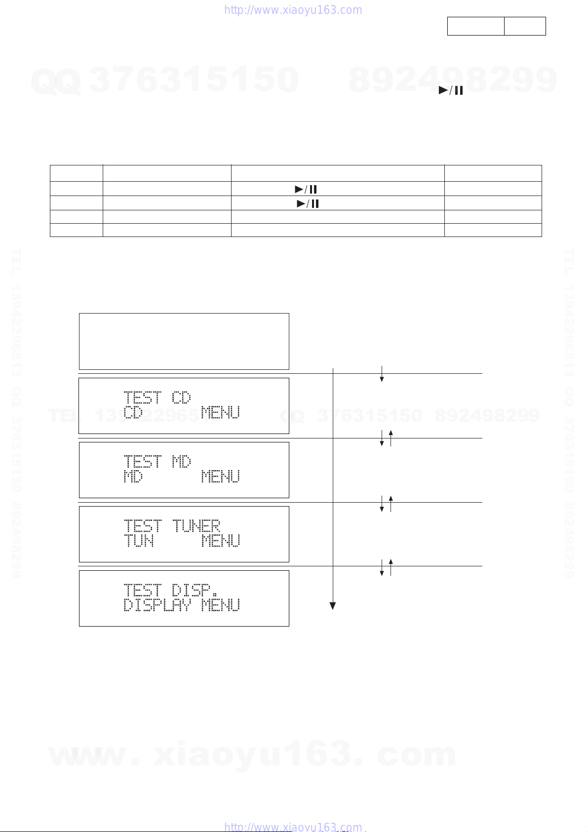
Denon D-AJ03 User manual

SERVICE MANUAL
MODEL
D-AJ03
PERSONAL AUDIO SYSTEM
For U.S.A. & Canada model
16-11, YUSHIMA 3-CHOME, BUNKYOU-KU, TOKYO 113-0034 JAPAN
X0178V.01 DE/CDM 0307
注 意
サービスをおこなう前に、このサービスマニュアルを
必ずお読みください。本機は、火災、感電、けがなど
に対する安全性を確保するために、さまざまな配慮を
おこなっており、また法的には「電気用品安全法」に
もとづき、所定の許可を得て製造されております。
従ってサービスをおこなう際は、これらの安全性が維
持されるよう、このサービスマニュアルに記載されて
いる注意事項を必ずお守りください。
● 本機の仕様は性能改良のため、予告なく変更すること
があります。
● 補修用性能部品の保有期間は、製造打切後 8年です。
Some illustrations using in this service manual are
slightly different from the actual set.
●
●
Please use this service manual with referring to
the operating instructions without fail.
●
For purposes of improvement, specifications and
design are subject to change without notice.
●
修理の際は、必ず取扱説明書を参照の上、作業を行って,
ください。
● 本文中に使用しているイラストは、説明の都合上現物
と多少異なる場合があります。
Ver. 1
w
w
w
.
x
i
a
o
y
u
1
6
3
.
c
o
m
Q
Q
3
7
6
3
1
5
1
5
0
9
9
2
8
9
4
2
9
8
T
E
L
1
3
9
4
2
2
9
6
5
1
3
9
9
2
8
9
4
2
9
8
0
5
1
5
1
3
6
7
3
Q
Q
TEL 13942296513 QQ 376315150 892498299
http://www.xiaoyu163.com

2
2
D-AJ03
SAFETY PRECAUTIONS
Thefollowingcheckshouldbeperformedforthecontinuedprotectionofthecustomerandservicetechnician.
LEAKAGE CURRENT CHECK
Beforereturningtheunittothecustomer,makesureyoumakeeither(1)aleakagecurrentcheckor(2)alinetochassis
resistancecheck.Iftheleakagecurrentexceeds0.5milliamps,oriftheresistancefromchassistoeithersideofthe
powercordislessthan460kohms,theunitisdefective.
LASER RADIATION
Donotstareintobeamorviewdirectlywithopticalinstruments,class3Alaserproduct.
(1)
(2)
500V
1M
(1)
(2)
w
w
w
.
x
i
a
o
y
u
1
6
3
.
c
o
m
Q
Q
3
7
6
3
1
5
1
5
0
9
9
2
8
9
4
2
9
8
T
E
L
1
3
9
4
2
2
9
6
5
1
3
9
9
2
8
9
4
2
9
8
0
5
1
5
1
3
6
7
3
Q
Q
TEL 13942296513 QQ 376315150 892498299
http://www.xiaoyu163.com

3
3
D-AJ03
DISASSEMBLY
(Follow the procedure below in reverse order when reassembling)
1. Rear Cover & Front Panel
1) Remove 14 rear screws
1
and 4 (E3: 2) bottom screws
2
on the Rear Cover.
2) Disconnect connectors and wire
3
~
7
on the Front Panel.
The Rear Cover and Front Panel can be detached
respectively.
2. Main P.W.B.
1) Remove 5 screws
8
.
2) Disconnect 2 FFCs, 8 connectors on the Main P.W.B.
4
5P Connector
5
8P Connector
6
11P Connector
12P Connector
7
1P Earth Lug
8
Connectors
Main P.W.B.
Connectors
FFC
FFC
3P Connector
8
2
1
1
1
w
w
w
.
x
i
a
o
y
u
1
6
3
.
c
o
m
Q
Q
3
7
6
3
1
5
1
5
0
9
9
2
8
9
4
2
9
8
T
E
L
1
3
9
4
2
2
9
6
5
1
3
9
9
2
8
9
4
2
9
8
0
5
1
5
1
3
6
7
3
Q
Q
TEL 13942296513 QQ 376315150 892498299
http://www.xiaoyu163.com

4
4
D-AJ03
3. CD Mecha. Chassis
1) Remove 4 each screws
ı
and
ıı
from the front side to
detach the CD Door Lens and CD Door Bracket.
2) Remove 6 screws
ıˇ
and take off the Main Chassis.
4. CD Mecha.
1) Remove 4 screws
ı
fixing the Bracket.
2) Detach the CD Mecha. upward as shown to the arrow
direction.
ı
ı
Rubber
(Green) Collar
(White)
Rubber
(Green)
Rubber
(Blue)
ıˇ
ı
ıı
ıı
CD Door Bracket
Main Chassis
CD Door Lens
ı
10
10
10
11
11
11
12
12
13
13
13
w
w
w
.
x
i
a
o
y
u
1
6
3
.
c
o
m
Q
Q
3
7
6
3
1
5
1
5
0
9
9
2
8
9
4
2
9
8
T
E
L
1
3
9
4
2
2
9
6
5
1
3
9
9
2
8
9
4
2
9
8
0
5
1
5
1
3
6
7
3
Q
Q
TEL 13942296513 QQ 376315150 892498299
http://www.xiaoyu163.com

5
5
D-AJ03
5. Speaker Box (L & R)
1) Remove 4 screws
ı
.
2) Disconnect 2 connectors.
7. Power P.W.B.
1) Remove 6 screws
ı
.
2) Disconnect 1 connector.
6. Tuner P.W.B.
1) Remove 2 screws
ı
.
ı
ı
ı
ı
Speaker
Box (L)
Speaker
Box (R)
Tuner P.W.B.
Power P.W.B.
Connector
ı
14
16
14
15
16
14
15
16
w
w
w
.
x
i
a
o
y
u
1
6
3
.
c
o
m
Q
Q
3
7
6
3
1
5
1
5
0
9
9
2
8
9
4
2
9
8
T
E
L
1
3
9
4
2
2
9
6
5
1
3
9
9
2
8
9
4
2
9
8
0
5
1
5
1
3
6
7
3
Q
Q
TEL 13942296513 QQ 376315150 892498299
http://www.xiaoyu163.com

6
6
D-AJ03
6
ADJUSTMENT
TUNER SECTION
Connections and adjustment point
AM FMG
AM SG
FM stereo modulator
FM SG
Modulation frequency: 400Hz
Modulation factor: 30%
Test loop antenna
Loop antenna
To TP
To Output Terminal
Digital Voltmeter
Distortion Meter
Separation Meter or
Electronic Voltmeter
To Output Terminal
Antenna Terminal
Rear Panel Side
75 ohms
Coaxial Cable
Modulation frequency: 1kHz
L+R: 90% (67.5kHz Dev.)
Pilot: 10% (7.5kHz Dev.)
75kHz Dev.: 100%
60cm
T401
T404
TUNER PWB
T403 T402
R419
R425TC401
FM ALIGNMENT (BAND BUTTON: FM, AUTO) Input Output
Step Alignment
Item Tune-in Point
(Channel Setting) Measuring
Equipment Frequency Level Modulation Connect to Measuring
Equipment Connect to Align Part Set Value Remarks
1FM DC
Balance 98 MHz FM SG 98 MHz 60 dB 1kHz
75 kHz dev FM Ant
Terminal Digital
Voltmeter Both Leads
of R425 T404 20mV Align with Mono
Modulation Signal
AM ALIGNMENT (BAND BUTTON: AM) Input Output
Step Alignment
Item Tune-in Point
(channel Setting) Measuring
Equipment Frequency Level Modulation Connect to Measuring
Equipment Connect to Align Part Set Value Remarks
E3:520 kHz T403 E3: 1.0±50mV
1 Band Edge E3:1710 kHz
Digital
Voltmeter Both Leads
of R419 Approx.
E3: (8.3±0.5V) No Adjustment
Required
2 IF No Broadcast Area AM SG (900 kHz) No AGC
Effects 400 Hz 30% Loop Ant Electronic
Voltmeter
LINE 1
Output
Terminal T401 Maximum
Output
3Tracking E3:600 kHz AM SG E3: 600 kHz No AGC
Effects 400 Hz 30% Loop Ant Electronic
Voltmeter
LINE 1
Output
Terminal T402 Maximum
Output
4Tracking E3:1400 kHz AM SG E3: 1400 kHz No AGC
Effects 400 Hz 30% Loop Ant Electronic
Voltmeter
LINE 1
Output
Terminal TC401 Maximum
Output
5 Repeat Steps 3 and 4, and set the output to maximum.
w
w
w
.
x
i
a
o
y
u
1
6
3
.
c
o
m
Q
Q
3
7
6
3
1
5
1
5
0
9
9
2
8
9
4
2
9
8
T
E
L
1
3
9
4
2
2
9
6
5
1
3
9
9
2
8
9
4
2
9
8
0
5
1
5
1
3
6
7
3
Q
Q
TEL 13942296513 QQ 376315150 892498299
http://www.xiaoyu163.com

7
7
D-AJ03
CD SECTION
1. RF level Confieming
CD Servo Micon PWB Probe
Oscilloscope
RF0
V
REF
10:1 +
Connection
1. Press CD Play/Pause ( ) button
to make it playback state.
2. Measure Iop.
Step
Eye Pattern
2. Pickup
Connection
Step
• Set input mode to
ALTERNATE or
CHOPPER.
CheckOscilloscope
A
A=0.8~1.2V
1. Press CD Play/Pause ( ) button
to make it playback state.
2. Check RF level with oscilloscope.
3. Confirm that the waveform is in good
shape.
(eye pattern in center must be
able to discriminate clearly.)
VH
50mV/div 0.2 s/div
or
0.5 s/div
• Since this CD system has the built-in automatic adjustment function, re-adjustment is not necessary when replacing the
pickup.
Therefore, any combination of PWB and pickup can be made freely.
As the automatic adjustment is performed every time the disc is changed, each disc can be played in the most
appropriate condition.
R108
w
w
w
.
x
i
a
o
y
u
1
6
3
.
c
o
m
Q
Q
3
7
6
3
1
5
1
5
0
9
9
2
8
9
4
2
9
8
T
E
L
1
3
9
4
2
2
9
6
5
1
3
9
9
2
8
9
4
2
9
8
0
5
1
5
1
3
6
7
3
Q
Q
TEL 13942296513 QQ 376315150 892498299
http://www.xiaoyu163.com

8
8
D-AJ03
BLOCKDIAGRAM
MAIN UNIT
un5V(MICON)
(tuner,AUDIO)
(MD)
(CD)
4p
Terminal
P.W.B.
LCD
8com,60seg
LCD
Controller
LC75811W
DISPLAY UNIT
BACK light
TUNER UNIT
FM FRONTEND
KCF216
FM IF/DET/MPX
AM RF/IF/DET
LA1844
PLL
LC72131
MICRO
COMPUTER
M38199
ELE.VR SYSTEM
LC75342M
DSP
TC94A14FA
RF AMP
TA2157F
Motor driver
LA6558 CD MECHA
CD4LXWNK
AUX IN
SUB
WOOFER
(There is no MD Section in the U.S.A. and Canada model)
REMOTE
Sensor TACT KEY
Reset
MUTING
Power AMP
BA5415
AC IN
- |<| -
6V
10V
6V
8V
Door driver
BA6286 CD DOOR
Reg.
BLOCK DIAGRAM
w
w
w
.
x
i
a
o
y
u
1
6
3
.
c
o
m
Q
Q
3
7
6
3
1
5
1
5
0
9
9
2
8
9
4
2
9
8
T
E
L
1
3
9
4
2
2
9
6
5
1
3
9
9
2
8
9
4
2
9
8
0
5
1
5
1
3
6
7
3
Q
Q
TEL 13942296513 QQ 376315150 892498299
http://www.xiaoyu163.com

9
9
D-AJ03
TEST MODE
From power off state to TEST mode
To enter into the TEST mode, plug the AC cord to the wall outlet while pressing the CD PLAY (CD ) button and
TUNER button simultaneously.
The version information is displayed initially.
Thereafter press the SKIP UP/DOWN button to select the TEST mode and then press the CD STOP button to determine it.
Press the DIRECT key during version display to obtain the designated TEST mode directly.
Cancelling the TEST Mode
In each TEST mode, press the POWER button to display COMPLETE for 1 second and then cancel the TEST mode.
In the MD TEST mode, press the POWER button again.
SKIP-DOWN
SKIP-DOWN
SKIP-UP
With SKIP-UP button
Version display
to CD-PLAY
Version display
to MD-PLAY
Version display
to TUNER
Version display
SKIP-DOWN
SKIP-UP
Test mode
SKIP-DOWN
SKIP-UP
Fig.20 Test Mode Menu
No. TEST MODE DIRECT DISPLAY
1 CD TEST CD PLAY (CD ) CD MENU
2 MD TEST MD PLAY (MD ) MD MENU
3
4
TUNER TEST
DISPLAY TEST
TUNER
VOL DOWN
TUN MENU
DISPLAY MENU
TEST MODE
w
w
w
.
x
i
a
o
y
u
1
6
3
.
c
o
m
Q
Q
3
7
6
3
1
5
1
5
0
9
9
2
8
9
4
2
9
8
T
E
L
1
3
9
4
2
2
9
6
5
1
3
9
9
2
8
9
4
2
9
8
0
5
1
5
1
3
6
7
3
Q
Q
TEL 13942296513 QQ 376315150 892498299
http://www.xiaoyu163.com

10
10
D-AJ03
1. CD test
Outline: Readout of the set value after automatic adjustment (for judging difference from initial value)
Forced operation of pickup (Inner/Outer circumference feed)
During the PLAY mode, the number of errors accumulated for 10 seconds (750 frames) is displayed.
Basic CD operation by CD-PLAY button
During the TEST mode, the display is turned on and the following buttons become effective.
Operation
1. CD-PLAY: CD operation according to steps
STEP 1: LD ON by pressing CD PLAY button in the stop mode
STEP 2: Focus On by pressing CD PLAY button in STEP 1
STEP 3: CLV servo ON by pressing CD PLAY button in STEP 2
STEP 4: Tracking servo ON by pressing CD PLAY button in STEP 3
STEP 5: Sub-code readout/display by pressing CD PLAY button in STEP 4
* Keep pressing the CD PLAY button for more than 1 second to shift to STEP 5 directly.
2. CD STOP : To stop the playback operation (shifting from each step to the stop
mode) / To reset display (during display of coefficient)
3. CD SKIP-UP ( ) : Forcible shift in the pickup FWD direction
4. CD SKIP-DOWN ( ) : Forcible shift in the pickup REV direction
Sliding is stopped when the PU_IN switch is turned on.
5. TUNER : Automatic adjustment (at the present pickup position)
6. POWER : Canceling the test mode
7. VOLUME UP/DOWN : To read the coefficient register while the CD operation is stopped/
To display the error number during CD playback
8. CD OPEN/CLOSE : Normal open/close operation
Readout of the adjusted value
Press the VOL.UP/DOWN button during the stop mode to read the following items.
Press the CD-STOP button to return to the normal display.
Item Display Max Type Min
Focus balance _ _ F B : x x 7 F 0 0 8 0
Focus gain _ _ F G : x x 1 F 0 0 E 0
Tracking balance _ _ T B : x x 7 F 0 0 8 0
Tracking gain _ _ T G : x x 1 F 0 0 E 0
Foucus offset F O F F : x x 7 F 0 0 8 0
Tracking offset T O F F : x x 7 F 0 0 8 0
RFRP R F R P : x x 7 F 0 0 8 0
Even if the CD-PLAY button is pressed initially, automatic adjustment is not obtained. Press the TUNER button in
the stop mode to gain CD-PLAY for automatic adjustment. Thereafter press the CD-STOP button to stop automatic
adjustment.
Press the VOL. UP/DOWN button to display automatically adjusted values.
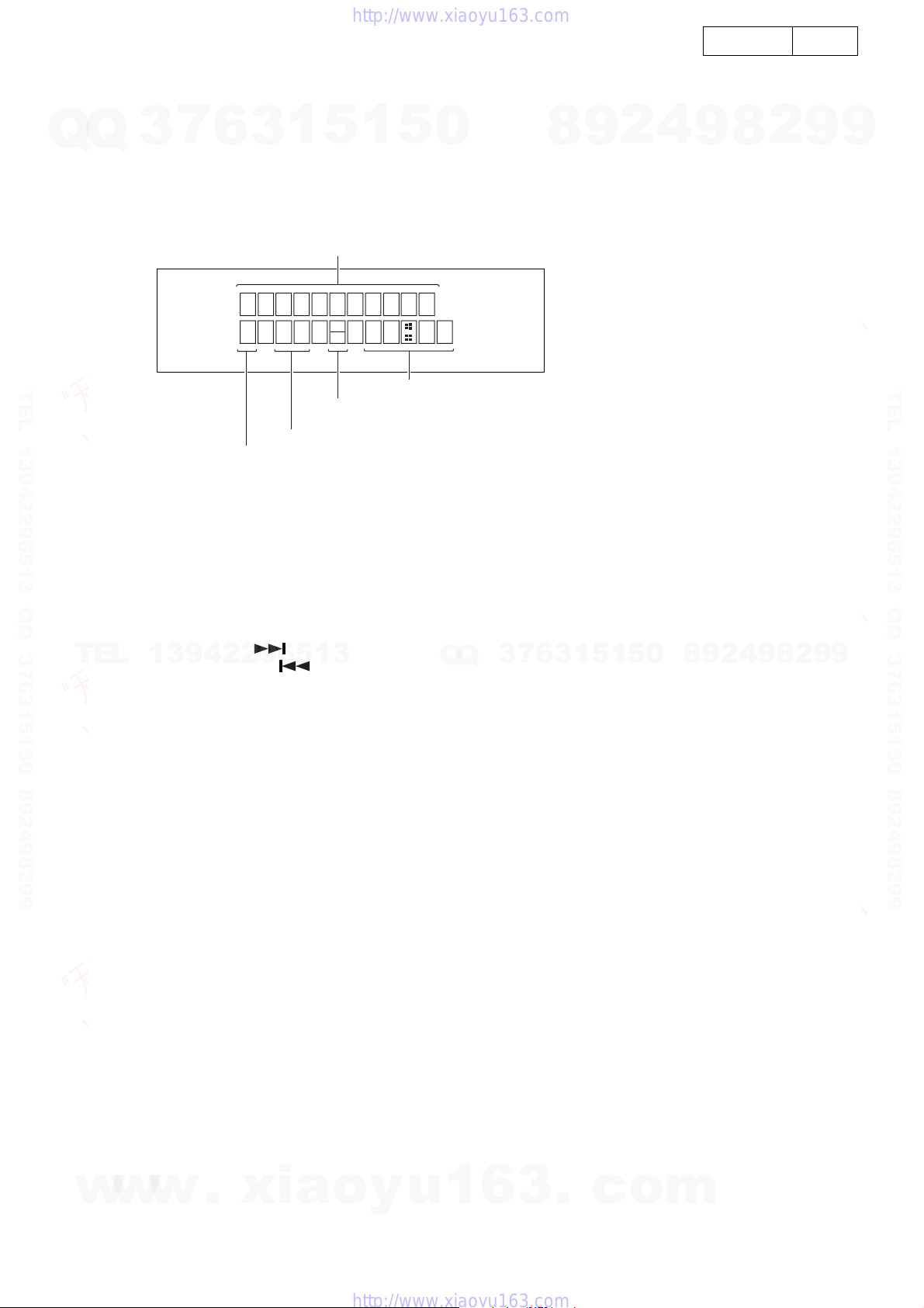
Readout of error numbers
Press the VOL.UP/DOWN button during playback to display the number of errors accumulated for 10 seconds
(750 frames).
Press the CD-STOP button during ERR display to return to the normal TEST mode display.
STEP NO Display
N:NORMAL SPEED
H:HIGH SPEED
TNO Display
Error Display
Time Display
N
H
w
w
w
.
x
i
a
o
y
u
1
6
3
.
c
o
m
Q
Q
3
7
6
3
1
5
1
5
0
9
9
2
8
9
4
2
9
8
T
E
L
1
3
9
4
2
2
9
6
5
1
3
9
9
2
8
9
4
2
9
8
0
5
1
5
1
3
6
7
3
Q
Q
TEL 13942296513 QQ 376315150 892498299
http://www.xiaoyu163.com

11
11
D-AJ03
Readout of coefficient
2.Time display: Blank from the stop
mode to STEP 4
1.STEP NO. : 0 when stopped
CD TEST
N
H
STEP NO Display
Coefficient name Coefficient
N:NORMAL SPEED
H:HIGH SPEED
STEP NO Display
TNO Display
Error Display
Time Display
ANA
TNO Display Time Display
w
w
w
.
x
i
a
o
y
u
1
6
3
.
c
o
m
Q
Q
3
7
6
3
1
5
1
5
0
9
9
2
8
9
4
2
9
8
T
E
L
1
3
9
4
2
2
9
6
5
1
3
9
9
2
8
9
4
2
9
8
0
5
1
5
1
3
6
7
3
Q
Q
TEL 13942296513 QQ 376315150 892498299
http://www.xiaoyu163.com

12
12
D-AJ03
No
No
No
No
No
No
TROUBLESHOOTING OF CD
CD SECTION
When the CD does not function
When the CD section does not operate when the objective lens of the optical pickup is dirty, this section may not operate.
Clean the objective lens, and check the playback operation. When this section does not operate even after the above step
is taken, check the following items.
Remove the cabinet and follow the trouble shooting instructions.
“Track skipping and/or no TOC (Table of Contents) may be caused by build up of dust other foreign matter on the laser
pickup lens. Before attempting any adjustment make certain that the lens is clean. If not, clean it as mentioned below.”
Turn off the power, and wipe the lens softly using a cleaning paper moistened with commercially available cleaning solution
so as not to damage it.
Be careful not to touch the lens with bare hands.
Dust gradually accumulates on the objective lens during use, and it may degrade performance. To avoid this problem, use
a cleaning disc designed for CD optical pickup lenses.
Does the unit switch from the CD test mode 1 to 2 ?
When the CD test mode is changed from 2 to 3, does the
disc motor rotate properly ?
Refer to "The disc motor CLV servo is defective".
Yes
Yes
Yes
When a disc is loaded, the power is turned on, and the CD (stop) button is pressed, is +7.2V applied to the collector of TR102 and +5.0V to
the emitter ? Is +3.3V applied to pin 22 on IC145 ?
Is the output at pin 19(HF) of IC146 flat in the CD test mode 4 ? Refer to "HF is abnormal".
Is sound output when the pickup lens is moved to where a
track is located by pressing the (button) and (button)
in the CD test mode 5 ?
Does the sled motor run ?
Yes
Yes
Are tracks played from the track 1 in ascending order by
pressing the (button) ?
Yes
No
Refer to "The sled motor
does not run".
No
Refer to "No sound is heard".
Yes
When the unit is turned off and on again, is it initialized ? Has the optical pickup
returned to the inner
periphery position ?
Yes
Yes
No Is the optical pickup in
switch in the OFF state ?
The optical pickup in-switch
is defective (ON state).
Check the
microcomputer
PWB.
The optical
pickup in
switch is
defective.
OFF ON
Refer to "Track search is impossible".
Normal
Yes
Is the voltage applied as shown in the wiring diagram ? Check the power circuit in the main unit.
Is the laser lit in the CD test mode 1 ? Refer to "The laser does not light up".
Refer to "Out of focus".
No
w
w
w
.
x
i
a
o
y
u
1
6
3
.
c
o
m
Q
Q
3
7
6
3
1
5
1
5
0
9
9
2
8
9
4
2
9
8
T
E
L
1
3
9
4
2
2
9
6
5
1
3
9
9
2
8
9
4
2
9
8
0
5
1
5
1
3
6
7
3
Q
Q
TEL 13942296513 QQ 376315150 892498299
http://www.xiaoyu163.com

13
13
D-AJ03
The laser does not light up
No
No
No
Is +1.8V applied to pin 10 of CX151 ?
The optical pickup is defective if CX151 is normal.
Yes
Yes
Yes
Is 1.5V applied to the LDO terminal of pin 7 of IC146 ? IC146 is defective
Is +1.8V applied to the collector of TR101 ?
The PWB pattern has been cut between TR101 and pin 10
of CX151.
Is +3.3V applied to C109 of R108 ? R108 is defective.
No
Check the +3.3V stabilization circuit of IC145 and L103.
Yes
No
Yes
Yes
Does the pickup lens go up and down when removing the
disc ?
Refer to "The triangular wave for focus servo does not
appear".
Check the optical pickup wires. If OK, the optical pickup is
defective.
Out of focus
No
Is the waveform inputted at pin 15 on IC146 when loading a
disc ? <Refer to the waveform diagrams on page 31.>
IC146 is defective.
No
Normal
Is the output (tracking error signal) found at pin 4 and 5 on
IC145 in the CD test mode 3 ?
Check between IC145 and CX151. If OK, the optical pickup
is defective.
Check the parts around IC146. If OK, IC146 is defective.
HF is abnormal
Abnormal
Is tracking input found at pin 11 of IC146 ?
<Refer to the waveform diagrams on page 31.>
No
Yes
Check the parts around IC149. If OK, IC149 is defective.
Is the tracking output found at pin 34 in IC149 in the CD test
mode 4 ?
No
Yes
Check the parts around IC145. If OK, IC145 is defective.
Is there the output between pin 5 and 6 on IC145 ?
Yes
Check the portion between IC145 and CX151 and connection of the optical pickup wires. If OK, the optical pickup is defective.
No
Does the sled motor run by pressing the / button in
the test mode ?
Refer to "The sled motor does not run".
IC146 is defective.
Track search is impossible
Is the waveform outputted to pin 11 and 17 on IC146 when a
track is jumped ?
<Refer to the waveform diagrams on page 31.>
No
Yes
IC149 is defective.
Is the waveform output found at pin 34 and 40 on IC149 when
a track is jumped ?
<Refer to the waveform diagrams on page 32.>
Yes
Yes
No If the parts around IC145 are normal, IC145 is defective.
Is the slide output found at pin 25 and 26 on IC145, and the
tracking output at pin 5 and 6 ?
Yes
Check the portion between IC145 and CX151 and connection of the optical pickup wires. If OK, the optical pickup is defective.
Check the portion between IC145 and CX062, sires and periphery of the sled spin motor. If OK, the motor is defective.
No
w
w
w
.
x
i
a
o
y
u
1
6
3
.
c
o
m
Q
Q
3
7
6
3
1
5
1
5
0
9
9
2
8
9
4
2
9
8
T
E
L
1
3
9
4
2
2
9
6
5
1
3
9
9
2
8
9
4
2
9
8
0
5
1
5
1
3
6
7
3
Q
Q
TEL 13942296513 QQ 376315150 892498299
http://www.xiaoyu163.com

14
14
D-AJ03
0.3-1.5 seconds
0.3-1.5 seconds
5V
The triangular wave for focus servo does not appears
No
No
No
The connection of CX151 is poor or the optical pickup is defective.
Yes
Yes
Yes
Is +3.3V applied to pin 6 of IC149 ? The +3.3V line of IC149 is defective.
Does the triangular wave appear at pin 33 on IC149 ?
<Refer to the waveform diagrams on page 32.>
The connection of signal lines between pin 33 on IC149
and pin 13 on IC145 is poor.
Check the parts around pin 33 on IC149. If OK, IC149 is
defective.
Yes
Yes
Does the disc motor rotate in the CD test mode 3 ?
This disc motor CLV servo is defective
No
Does the disc motor rotate too rapidly or slowly ?
Does the eye pattern appear at pin 19 on IC146 ?
<Refer to the waveform diagrams on page 31>
(It is OK even if the waveform is not clear.)
Does the triangular wave appear at pin 13 on IC145 ?
<The same waveform as above>
No
Yes
Does the saw tooth wave appear between pins 13 and 16 of
IC145 ? <Refer to the waveform diagrams on page 32.>
Check the parts around IC145 and the power supply line. If
OK, IC145 is defective.
No The PWB pattern has been cut.
Does the saw tooth wave appear between pins 13 and 16 of
CX151 ? <The same waveform as above>
Yes
No
Yes
Is the eye pattern Vp-p 1.2V inputted to the pin 24 on IC149 ? No
Yes
IC149 is defective.
(After checking the parts around it, replace it.)
Is the voltage applied
between pins 27 and 28 of
IC1 for about 0.3-1.5 seconds
when switching from the CD
test mode 2 to 3 ?
The disc motor is
defective or wires
have broken.
Yes
Is the pin 41 on IC149 in the
high state for 0.3-1.5
seconds and does it pulse
when switching from the CD
test mode 2 to 3 ?
<Refer to the waveform
diagrams on page 31>
No IC149 is defective.
IC149 is defective or wires have broken.
Recheck whether the optical pickup objective is dirty.
If it is dirty, clean it.
Check the connection between pin 19 on IC146 and pin 24
on IC149. If OK, the optical pickup is defective.
Check the PWB pattern and C155.
No
Yes
w
w
w
.
x
i
a
o
y
u
1
6
3
.
c
o
m
Q
Q
3
7
6
3
1
5
1
5
0
9
9
2
8
9
4
2
9
8
T
E
L
1
3
9
4
2
2
9
6
5
1
3
9
9
2
8
9
4
2
9
8
0
5
1
5
1
3
6
7
3
Q
Q
TEL 13942296513 QQ 376315150 892498299
http://www.xiaoyu163.com

15
15
D-AJ03
No sound is heard
No
No
No
Yes
Yes
Is the digital signal outputted from the pin 4 (digital OUT) of
IC149 ?
Check the parts around IC149. If OK, IC149 is defective.
Is digital signal outputted from the pin 8 (digital OUT) of
IC150 ?
Check the CD/MD connection sections.
Check the parts around IC150. If OK, IC150 is defective.
Is the digital signal sent to the pin 26 of CX281 ?
Yes
OK
The slide motor does not run
No
No
No
Yes
Yes
Is the slide feed signal outputted to pin 40 of IC149 by
pressing the / button in the test mode ?
Check the connection of parts around IC149. If OK, IC149
is defective.
Is the slide feed signal outputted between pins 25 and 26 of
IC145 ?
Check the PWB pattern.
Check the connection between pin 20 of IC145 and pin 40 of
IC149. If OK, IC145 is defective.
Is the slide feed voltage applied to both edges of the sled
motor ?
Yes
Check the slide motor. If the sled motor does not run when the DV2.0V is applied to its terminal. It is defective.
w
w
w
.
x
i
a
o
y
u
1
6
3
.
c
o
m
Q
Q
3
7
6
3
1
5
1
5
0
9
9
2
8
9
4
2
9
8
T
E
L
1
3
9
4
2
2
9
6
5
1
3
9
9
2
8
9
4
2
9
8
0
5
1
5
1
3
6
7
3
Q
Q
TEL 13942296513 QQ 376315150 892498299
http://www.xiaoyu163.com

16
16
D-AJ03
1
T
1
T
Stopped
2000/09/18 16:56:26
CH1=200mV
DC 10:1
IC146
11pin
TEO
5ms/div
(5ms/div)
NORM:200kS/s
CH1 V/DIV
VAR
=Filter= =Offset= =Record Length= =Trigger=
Type : EDGE CH1
Hold off : MINIMUM
Mode : AUTO
Delay : 102.3ns
Smoothing : ON CH1 : 0.000V Main : 10K
Zoom : 4KCH2 : 0.00V
CH3 : 0.00V
CH4 : 0.00V
BW : 20MHz
CAL
CH1
V/DIV
200mV
Tracking error
Tracking
Disc playback
When there is no
wound in the disc.
By the test
mode 3
Track jump
When a door
was closed,
disc dovetail
Disc playback
1
T
1
T
Stopped
2000/09/18 16:55:04
CH1=1V
DC 10:1
IC146
11pin
TEO
5ms/div
(5ms/div)
NORM:200kS/s
CH1 V/DIV
VAR
=Filter= =Offset= =Record Length= =Trigger=
Type : EDGE CH1
Hold off : MINIMUM
Mode : AUTO
Delay : 102.3ns
Smoothing : ON CH1 : 0.00V Main : 10K
Zoom : 4KCH2 : 0.00V
CH3 : 0.00V
CH4 : 0.00V
BW : 20MHz
CAL
CH1
V/DIV
1V
1
T
1
T
2
Stopped
2000/09/18 17:01:23
CH1=1V
DC 10:1
CH2=1V
DC 10:1
IC146
11pin
TEO
2
IC146
17pin
RFRP
2ms/div
(2ms/div)
NORM:500kS/s
CH2 CH3 CH4 EXT LINE
=Filter= =Offset= =Record Length= =Trigger=
Type : EDGE CH1
Hold off : MINIMUM
Mode : SINGLE
Delay : 102.3ns
Smoothing : ON CH1 : 0.00V Main : 10K
Zoom : 5KCH2 : 0.00V
CH3 : 0.00V
CH4 : 0.00V
BW : 20MHz
CH1
Level
0.54V
3
4
5
T
T
1
2
3
Stopped
2000/09/18 15:29:21
CH1=500mV
DC 10:1
CH2=2V
DC 10:1
CH3=2V
DC 10:1
IC145
4pin
FO+
IC145
3pin
FO
-
IC146
15pin
FEO
2ms/div
(2ms/div)
NORM:500kS/s
=Filter= =Offset= =Record Length= =Trigger=
Type : EDGE CH2
Hold off : MINIMUM
Mode : SINGLE
Delay : 102.3ns
Smoothing : ON CH1 : 0.000V Main : 10K
Zoom : 5KCH2 : 0.00V
CH3 : 0.00V
CH4 : 0.00V
BW : 20MHz
CH2
Level
2.48V
Foucus servo on
During the tracking jump TEO, RFRP Disc motor and CD related signal
CH1 CH3 CH4 EXT LINE
CH2
6
T
T
1
Stopped
2000/09/18 14:55:22
CH1=500mV
DC 10:1
IC146
19pin
RFGO
500ms/div
(500ms/div)
NORM:200kS/s
=Filter= =Offset= =Record Length= =Trigger=
Type : EDGE CH1
Hold off : MINIMUM
Mode : SINGLE
Delay : 102.3ns
Smoothing : ON CH1 : 0.000V Main : 1K
Zoom : 400CH2 : 0.00V
CH3 : 0.000V
CH4 : 0.00V
BW : 20MHz
RF
Format
BMP
FileName AutoFile
OFF ON
To
TopMenu
CH1
7
T
1
T
2
3
Stopped
2000/09/18 16:45:07
CH1=1V
DC 10:1
CH2=1V
DC 10:1
CH3=1V
DC 10:1
IC149
41pin
DMO
8
IC146
12pin
RFDC
2
IC146
17pin
RFRP
500ms/div
(500ms/div)
NORM:2kS/s
=Filter= =Offset= =Record Length= =Trigger=
Type : EDGE CH1
Hold off : MINIMUM
Mode : SINGLE
Delay : 102.3ns
Smoothing : ON CH1 : 0.00V Main : 10K
Zoom : 4KCH2 : 0.00V
CH3 : 0.00V
CH4 : 0.00V
BW : 20MHz
CH3
V/DIV
1V
CD test 2 3
upgrade
WAVEFORMS OF CD CIRCUIT
w
w
w
.
x
i
a
o
y
u
1
6
3
.
c
o
m
Q
Q
3
7
6
3
1
5
1
5
0
9
9
2
8
9
4
2
9
8
T
E
L
1
3
9
4
2
2
9
6
5
1
3
9
9
2
8
9
4
2
9
8
0
5
1
5
1
3
6
7
3
Q
Q
TEL 13942296513 QQ 376315150 892498299
http://www.xiaoyu163.com

17
17
D-AJ03
9
T
2
1
Stopped
2000/09/18 17:12:20
CH1=200mV
DC 10:1
CH2=1V
DC 10:1
IC146
40pin
FMO
10
IC149
33pin
FOO
100ms/div
(100ms/div)
NORM:10kS/s
CH1 V/DIV
VAR
=Filter= =Offset= =Record Length= =Trigger=
Type : EDGE CH1
Hold off : MINIMUM
Mode : AUTO
Delay : 102.3ns
Smoothing : ON CH1 : 0.000V Main : 10K
Zoom : 5KCH2 : 0.00V
CH3 : 0.00V
CH4 : 0.00V
BW : 20MHz
CAL
CH1
V/DIV
200mV
Feed motor and tracking output
during the track jump
track jump
10
4
5
T
1
2
3
Stopped
2000/09/18 15:14:35
CH1=200mV
DC 10:1
CH2=2V
DC 10:1
CH3=1V
DC 10:1
IC149
33pin
FOO
IC145
4pin
FO+
IC145
3pin
FO
-
1s/div
(1s/div)
NORM:10kS/s
CH1 V/DIV
VAR
=Filter= =Offset= =Record Length= =Trigger=
Type : EDGE CH1
Hold off : MINIMUM
Mode : AUTO
Delay : 102.3ns
Smoothing : ON CH1 : 0.000V Main : 10K
Zoom : 5K
CH2 : 0.00V
CH3 : 0.00V
CH4 : 0.00V
BW : 20MHz
CAL
CH1
V/DIV
200mV
Focus search Normal focus actuator drive
It is actuated
normally.
When the door
was closed
without a disc.
7
T
1
T
2
3
Stopped
2000/09/18 16:42:08
CH1=1V
DC 10:1
CH2=1V
DC 10:1
CH3=5V
DC 10:1
IC149
41pin
DMO
IC146
26pin
SP+
11
12
IC146
25pin
SP
-
500ms/div
(500ms/div)
NORM:2kS/s
=Filter=
CH Position To
-3div -1div 0div +1div +3div
=Offset= =Record Length= =Trigger=
Type : EDGE CH1
Hold off : MINIMUM
Mode : SINGLE
Delay : 102.3ns
Smoothing : ON CH1 : 0.00V Main : 10K
Zoom : 5K
CH2 : 0.00V
CH3 : 0.00V
CH4 : 0.00V
BW : 20MHz
Disc motor output while in the test mode
13
T
T
1
Stopped
2000/09/18 17:16:55
CH1=1V
DC 10:1
IC145
5pin
TR+
500us/div
(500us/div)
NORM:2MS/s
=Filter= =Offset= =Record Length= =Trigger=
Type : EDGE CH1
Hold off : MINIMUM
Mode : AUTO
Delay : 102.3ns
Smoothing : ON CH1 : 0.00V Main : 10K
Zoom : 4K
CH2 : 0.00V
CH3 : 0.00V
CH4 : 0.00V
BW : 20MHz
CH1
V/DIV
1V
Normal track actuator drive
When there is no
wound in the disc.
IC1
5pin-6pin
When there is
a wound in the
disc.
CH1 V/DIV
VAR
4
5
T
T
1
Stopped
2000/09/18 17:18:51
CH1=1V
DC 10:1
IC145
3pin-4pin
FO+ FO
-
1ms/div
(1ms/div)
NORM:1MS/s
=Filter= =Offset= =Record Length= =Trigger=
Type : EDGE CH1
Hold off : MINIMUM
Mode : AUTO
Delay : 102.3ns
Smoothing : ON CH1 : 0.00V Main : 10K
Zoom : 5K
CH2 : 0.00V
CH3 : 0.00V
CH4 : 0.00V
BW : 20MHz
Disc playback
There is no
wound in the
disc.
CH1 V/DIV
VAR
CH1
T
1
T
Stopped
2000/09/18 17:25:20
CH1=1V
DC 10:1
IC145
5pin
TR+
13
1ms/div
(1ms/div)
NORM:1MS/s
=Filter= =Offset= =Record Length= =Trigger=
Type : EDGE CH1
Hold off : MINIMUM
Mode : AUTO
Delay : 102.3ns
Smoothing : ON CH1 : 0.00V Main : 10K
Trigger Knob
DELAY
Zoom : 5K
CH2 : 0.00V
CH3 : 0.00V
CH4 : 0.00V
BW : 20MHz
Actuator drive when damaged
CAL
CAL
CH1
V/DIV
1V
CH3
Position
-3.00div
CD test 2 3
upgrade
Trigger
Position
-1.00div
Trigger Position To
0div +4div
-
4div POSITION
w
w
w
.
x
i
a
o
y
u
1
6
3
.
c
o
m
Q
Q
3
7
6
3
1
5
1
5
0
9
9
2
8
9
4
2
9
8
T
E
L
1
3
9
4
2
2
9
6
5
1
3
9
9
2
8
9
4
2
9
8
0
5
1
5
1
3
6
7
3
Q
Q
TEL 13942296513 QQ 376315150 892498299
http://www.xiaoyu163.com

18
18
D-AJ03
IC’S
TMP91CY22 (IC600)
TMP91CY22 Terminal Function
P.No Symbol Port Name Port Function Voltage
(V)
1 VREFL VREF L I GND 0V
2 Avss AVSS I GND 0V
3Avcc AVCC I 3.3V 3.0V
4 P70/TAO IN CD_PU_IN I CD PU inner most detect, L: Inner most 0V
5 P71/TA1 OUT DR_OP_IN I CD DOOR open switch detect, L: OPEN 0V
6 P72/TA3 OUT DR_CL_IN I CD DOOR close switch detect, L: CLOSE 0V
7 P73/TA4 IN - O P.D 0V
8 P74/TA5 OUT DR_M- O Door MOTOR control, at CLOSE H PULSE 0V
9 P75/TA7 OUT DR_M+ O Door MOTOR control, at OPEN H PULSE 0V
10 P80/TB01N0/INT5 REMO_IN I P.U Remote input 3.0V
11 P81/TB01N1/INT6 P.DOWN I P.U Vref power control, H: Normal, L: P. down 3.0V
12 P82/TB0 OUT0 POWER O P.D Power ON/OFF, H: ON, L: STANDBY 3.0V
13 P83/TB0 OUT1 BL O P.D Backlight ON/OFF H:ON 3.0V
14 P84/TB1IN0/INT7 PCONT I MD Mech Power Abnormal detect L:Abnormal detect 3.0V
15 P85/TB1IN1/INT8 MD_RESET O MD RESET output L=RESET 3.0V
VREFL
1
VREFH
100
P57/AN7
99
P56/AN6
98
P55/AN5
97
P54/AN4
96
P53/AN3/ADTR G
95
P52/AN2
94
P51/AN1
93
P508AN0
92
DVS S
91
P66
90
DVCC
89
AV S S
2
AV C C
3
P70/TA0IN
4
P71/TA1OUT
5
P72/TA3OUT
6
P73/TA4IN
7
P74/TA5OUT
8
P75/TA7OUT
9
P80/TB0IN0/INT5
10
P81/TB0IN1/INT6
11
TOP VIEW
P82/TB0OUT0
12
P83/T B0OUT1
13
P84/TB1IN0/INT7
14
P85/TB 1IN1/INT 8
15
P86/TB1OUT0
16
P87/TB1OUT1
17
P90/TXD0
18
P91/RXD0
19
P 92/S C LK 0/C T S 0
20
P93/TXD1
21
P94/RX1
22
P 95/S C LK 1/C T S 1
23
AM0
24
DVCC
26
25
27
28
29
30
31
35
33
34
35
36
37
50
49
48
47
54
55
56
57
58
59
60
61
62
63
64
65
66
67
68
69
70
71
72
73
74
75
56
52
51
46
45
44
43
42
41
40
39
38
P06/AD6
P07/AD7
P10/AD8/A8
P11/AD9/A9
P12/AD10/A10
P13/AD11/A11
P14/AD12/A12
P15/AD13/A13
P16/AD14/A14
P17/AD15/A16
P20/A0/A16
P21/A1/A17
DVS S
NMI
DVCC
P22/A2/A18
P23/A3/A19
P24/A4/A20
P25/A5/A21
P26/A6/A22
P27/A7/A23
P30/R D
P31/WR
P32/HWR
P33/WAIT
P 34/B US R Q
76
P 35/B US AK
77
P36/R /W
78
P37
79
P 40/C S 0
80
P 41/C S 1
81
P 42/C S 2
82
P 43/C S 3
83
P 60/S C K
84
P 61/S O/S DA
85
P 62/S I/S CL
86
P63/INT0
87
P 64/S C OUT
88
P65
P05/AD5
P04/AD4
P03/AD3
P02/AD2
P01/AD1
P00/AD0
ALE
PA7
PA6
PA5
PA4
PA3/INT4
X2
DVS S
X1
AM1
RESET
P96/TX1
P97/TX2
EMU0
EMU1
PA0/INT1
PA1/INT2
PA2/INT3
w
w
w
.
x
i
a
o
y
u
1
6
3
.
c
o
m
Q
Q
3
7
6
3
1
5
1
5
0
9
9
2
8
9
4
2
9
8
T
E
L
1
3
9
4
2
2
9
6
5
1
3
9
9
2
8
9
4
2
9
8
0
5
1
5
1
3
6
7
3
Q
Q
TEL 13942296513 QQ 376315150 892498299
http://www.xiaoyu163.com

19
19
D-AJ03
16 P86/TB1 OUT0 MD_ST O 20ms H at CD music start 0V
17 P87/TB1 OUT1 MD_SEARCH O L: When CD play, H: Others 0V
18 P90/TXD0 MD_KDATA O MD KEY DATA 0V
19 P91/RXD0 MD_DATA I MD DATA input 0.8V
20 P92/SCLK0/CTS0 MD_D_SCK O MD CLOCK output 3.0V
21 P93/TXD1 - P.D 0V
22 P94/RX1 - P.D 0.4V
23 P95/SCLK1/CTS1 - O P.D 0.4V
24 AMO AMO I P.U 3.3V P.U 3.0V
25 DVcc DVCC I 3.3V 3.0V
26 X2 X2 16.000MHz 1.3V
27 DVss DVSS I GND 0V
28 X1 X2 16.000MHz 1.3V
29 AM1 AM1 I P.U 3.3V PU 3.0V
30 RESET RESET I P.U mcom reset input 3.0V
31 P96 XT1ÅiN) - O P.D 0V
32 P97 XT2(N) - O P.D 0V
33 EMU0 - -
34 EMU1 - -
35 PA0/INT1 SYS_STOP I P.U BACK-UP defect L:BACK Up mode 3.0V
36 PA1/INT2 H/P SW I P.U H/P detect SW, H:SP MUTE ON 0V
37 PA2/INT3 PROTECT I P.U Abnormal detect, L: Abnormal 3.0V
38 PA3/INT4 MD_D_STB I MD strobe input 1.5V
39 PA4 - O P.D 0V
40 PA5 LCD_RS O LCD MODULE Register select 3.2V
41 PA6 LCD_R/W O LCD MODULE R/W signal 0.1V
42 PA7 LCD_E O LCD MODULE enable signal 0V
43 ALE ALE O OPEN -
44 P00/AD0 LCD_DB0 O LCD MODULE control DATA 0 3.2V
45 P01/AD1 LCD_DB1 O LCD MODULE control DATA 1 3.2V
46 P02/AD2 LCD_DB2 O LCD MODULE control DATA 2 0.1V
47 P03/AD3 LCD_DB3 O LCD MODULE control DATA 3 0.1V
48 P04/AD4 LCD_DB4 O LCD MODULE control DATA 4 0.1V
49 P05/AD5 LCD_DB5 O LCD MODULE control DATA 5 0.1V
50 P06/AD6 LCD_DB6 O LCD MODULE control DATA 6 0.1V
51 P07/AP7 LCD_DV7 O LCD MODULE control DATA 7 0.1V
52 P10/AD8/A8 CD_BUS0 I/O CD I/F data in/output 0, L fixed when other than CD 3.2V
53 P11/AD9/A9 CD_BUS1 I/O CD I/F data in/output 1, L fixed when other than CD 3.2V
54 P12/PD10/A10 CD_BUS2 I/O CD I/F data in/output 2, L fixed when other than CD 3.2V
55 P13/AD11/A11 CD_BUS3 I/O CD I/F data in/output 3, L fixed when other than CD 3.2V
56 P14/AD12/A12 CD_BUCK O CD I/F data in/output, L fixed when other than CD 3.0V
57 P15/AD13/A13 CD_CCE O CD I/F CCE output, L fixed when other than CD 3.1V
58 P16/AD14/A14 CD_RESET O CD RESET output 3.0V
59 P17/AD15/A15 CD_FUNC O CD power control, H: Other than CD 0V
60 P20/A0/A16 SP_MUTE O P.D POWER AMP MUTE L:MUTE ON 3.1V
61 P21/A1/A17 SY_MUTE O P.D PREAMP MUTE L:MUTE ON 3.0V
62 DVSS DVSS I GND 0V
63 NMI NMI I P.U fixed(3.3V) 3.1V
64 DVCC DVCC I 3.3V 3.1V
65 P22/A2/A18 GVSW O CD-DA/CD-RW switching SW L:CD-RW 3.1V
66 P23/A3/A19 - I P.D 0V
67 P24/A4/A20 - I P.D 0V
68 P25/A5/A21 - O P.D 0V
69 P26/A6/A22 - O P.D 0V
70 P27/A7/A23 - O P.D 0V
P.No Symbol Port Name Port Function Voltage
(V)
OPEN
OPEN
EQ default setup L:FLAT H:ROCK
EQ gain setup H: Follow the Vol. L: Regulanty
w
w
w
.
x
i
a
o
y
u
1
6
3
.
c
o
m
Q
Q
3
7
6
3
1
5
1
5
0
9
9
2
8
9
4
2
9
8
T
E
L
1
3
9
4
2
2
9
6
5
1
3
9
9
2
8
9
4
2
9
8
0
5
1
5
1
3
6
7
3
Q
Q
TEL 13942296513 QQ 376315150 892498299
http://www.xiaoyu163.com

20
20
D-AJ03
71 P30/RD - O P.U 0
72 P31/WR - O P.U 0
73 P32/HWR OEM →V/H I P.D CD SET UP L:vertical(F.B:Nonadjustment) 0
74 P33/WAIT MODEL I MODEL Detecter H:03xMD L:03xCD 3.0V
75 P34/BUSRQ SDB_D I I SDB switching, L: 75342M use, H: 88pin L/H 0
76 P35/BUSAK - O P.D 0
77 P36/R/W - O P.D 0
78 P37/BOOT - O P.U 3.0V
79 P40/CS0 - O P.D 0
80 P41/CS1 - O P.D 0
81 P42/CS2 - O P.D 0
82 P43/CS3 - O P.D 0
83 P60/SCK IC_CLK O Clock for external control IC 0
84 P61/S0/SDA IC_DI O Data output for external control IC 0
85 P62/SI/SCL IC_DO I Data input for external control IC 3.0V
86 P63/INT0 IC_CE I Chip enable for external control IC 0
87 P64/SCOUT SYS_CLK O SYS.CLOCK OUT(OPEN) 1.4V
88 P65/ SDB_O O SDB switching, 75pin operate at H, H: ON 0
89 DVCC DVCC I 3.3v 3.0V
90 P66/ TU_MUTE O tuner MUTING terminal(H →L:MUTE) 3.0V
91 DVSS DVSS I GND 3.0V
92 P50/AN0 KEY1 I A/D KEY input 1 3.0V
93 P51/AN1 KEY2 I A/D KEY input 2 3.0V
94 P52/AN2 KEY3 I A/D KEY input 3 3.0V
95 P53/AN3/ADIRG P.W.B_TEST I P.D H: PWB check MODE, L: Normal 0
96 P54/AN4 SPAN I Frequency SPAN switch 0
97 P55/AN5 - I P.D 0
98 P56/AN6 TU_TU I TUNER TUNING DETECT(H →L:TUNING) 3.0V
99 P57/AN7 TU_ST I STEREO RECEIVE DETECT(H →L:STEREO RECEIVE) 3.0V
100 VREFH VREFH I 3.3V 3.0V
P.No Symbol Port Name Port Function Voltage
(V)
TEST POINT
w
w
w
.
x
i
a
o
y
u
1
6
3
.
c
o
m
Q
Q
3
7
6
3
1
5
1
5
0
9
9
2
8
9
4
2
9
8
T
E
L
1
3
9
4
2
2
9
6
5
1
3
9
9
2
8
9
4
2
9
8
0
5
1
5
1
3
6
7
3
Q
Q
TEL 13942296513 QQ 376315150 892498299
http://www.xiaoyu163.com
Other manuals for D-AJ03
2
Table of contents
Other Denon Stereo System manuals

Denon
Denon DCD-CX3 - CD/Super Audio CD Player User manual

Denon
Denon CEOL carino User manual

Denon
Denon HEOS Manual

Denon
Denon UDRA-70 User manual

Denon
Denon HEOS Amp User manual

Denon
Denon D-F10 User manual

Denon
Denon D-90 User manual

Denon
Denon D-A03 User manual

Denon
Denon SYS-A3L User manual

Denon
Denon D-M37 User manual