Dent Fix Equipment DF-SPR67 User manual

2-4 / 5-10 / 29-31 DF-SPR67
2-4 / 11-16 / 29-31
2-4 / 17-22 / 29-31
2-4 / 23-28 / 29-31
73502-V1-29/04/2015 dentfix.com
EN
DE
ES
FR
DF-SPR67
2
!
!
4
3
1
5
2
6
7
9
8
!
!
10
11
!
"#!
"$
!
%"
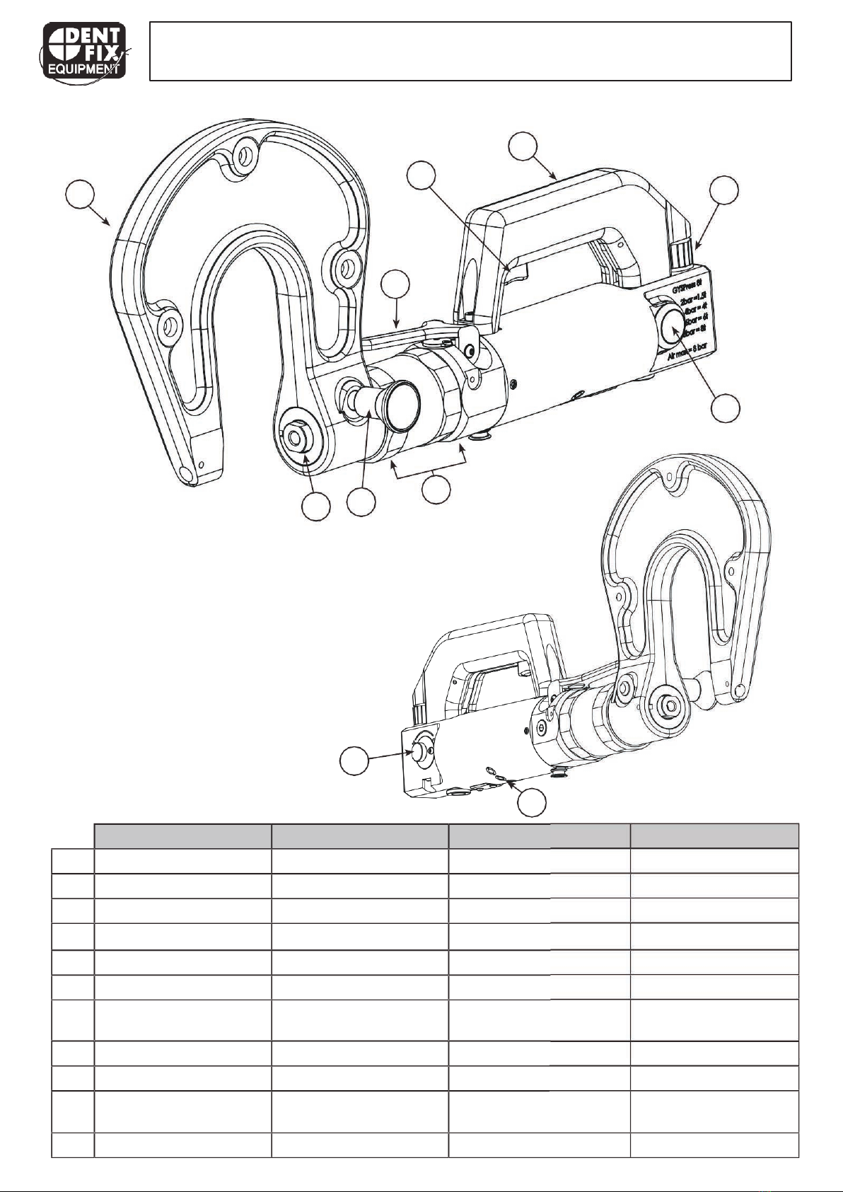
!&'!
(
!$)**+!,-.!/-,01!2*!,3*-1!
#4*)567*+
!/-,8!*9!,34*-!
:
!
%483;,-7*!+*<*-
!
=,+,93,!2*!2*83,-7,
!
"9)8>,99?978-4*7*+
!
@*<4*-!2*!2A3;,-7*
!
B
!
C-477*-
!D,)4++1!
$)*?*-?97)-477*-
!DE3;*))*!
F
!
G,92+*
!
H,971
!G,927-4II!
=1479A*
!
J
!=-*88?-*!319)-1+!
KL?8)*!2*!+,!>-*84M9
!
%-?3N-*7*+?97
!
'A7+,7*!>-*88419
!
O
!
'*7?+,)1-
!H,9M.*)-1!H,91.*)*-!H,91.P)-*!
Q
GR2-,?+43!34-3?4)!S4-3?4)1!;42-T?+431!D*83;+188*9*8!;R2-,?+483;*8!
$R8)*.!S4-3?4)!;R2-,?+4U?*!
V
@13N497!>49!=,8,21-!2*!5+1U?*1!
#4*)567*+,--*)4*-?97!
D1?>4++*!2*!5+13,7*
!
W
X,3N!,Y+*!"L*!34+Z92-431!
[*-N0*?7,?I9,;.*!
KY*!<A-49
!
(\
$>**2!319)-1+!KL?8)*!2*!+,!<*+1342,2!'*7*+?97![*-N0*?77*8]
!
3;^49247N*4)
!
!
'A7+,7*!<4)*88*
!
((
K4-!1?)>?)!&?7,!2*!,4-*!
@?I),?8+,_!
`3;,>>*.*9)!2a,4-
!
3
!
!
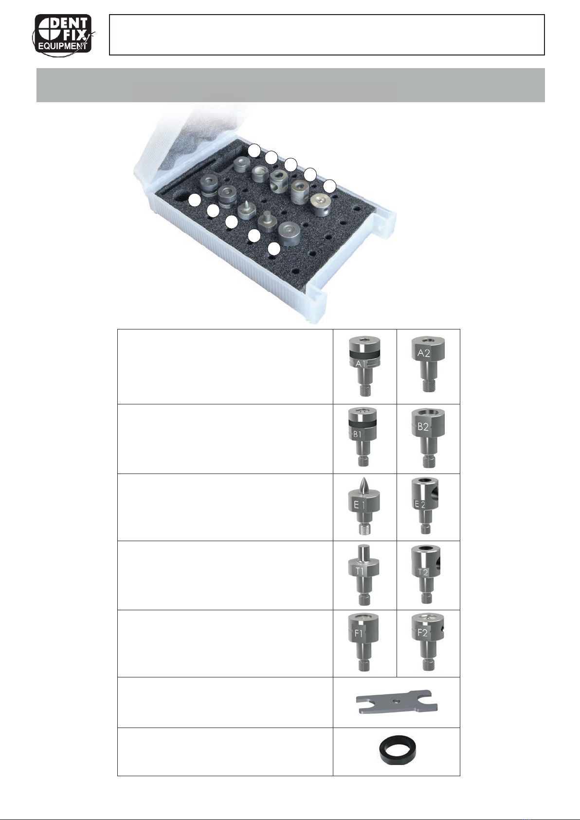
-Matrix for self-piercing rivets (RAP) Ø 3.3 mm
-Matrices para remaches autoperforantes Ø 3,3 mm
-Matrizen für Stanznieten (RAP) Ø 3,3 mm
-Matrices pour rivet auto-perçants (RAP) Ø 3,3 mm
-Matrix for self-piercing rivets (RAP) Ø 5.3 mm
-Matrices para remaches autoperforantes Ø 5,3 mm
-Matrizen für Stanznieten (RAP) Ø 5,3 mm
-Matrices pour rivet auto-perçants (RAP) Ø 5,3 mm
-Extraction mandrel
-Mandril de extracción
-Auspress-Satz
-Mandrin d’extraction
-Punching mandrel
-Mandril de perforación
-Vorstanz-/Kalibrierungssatz
-Mandrin de poinçonnage
-Matrix for Flow-Form rivet (RFF)
-Matrices para remache Flow-Form
-Matrizen für Fließformnieten (RFF)
-Matrices pour rivet Flow-Form (RFF)
-Kit of assembly keys
-Juego de llaves de montaje
-Montageschlüssel-Set
-Jeu de clés de montage
14
!
!
16
- Spare Elastomer ring
- Anillas de recambio de elastómero
-Ersatz-Dämpferringe
-Bagues de rechange en élastomère
!
x4
x2
!
DF-SPR67
A2
B2
E2
T2
F2
A1
B1
E1
T1
F1
CONNECTOR KIT CONTENTS / COMPOSICIÓN DEL KIT DE BOQUILLAS /
ZUSAMMENSTELLUNG DES MATRIZEN-KITS / COMPOSITION DU KITD’EMBOUTS
DF-SPR67
4
!
!
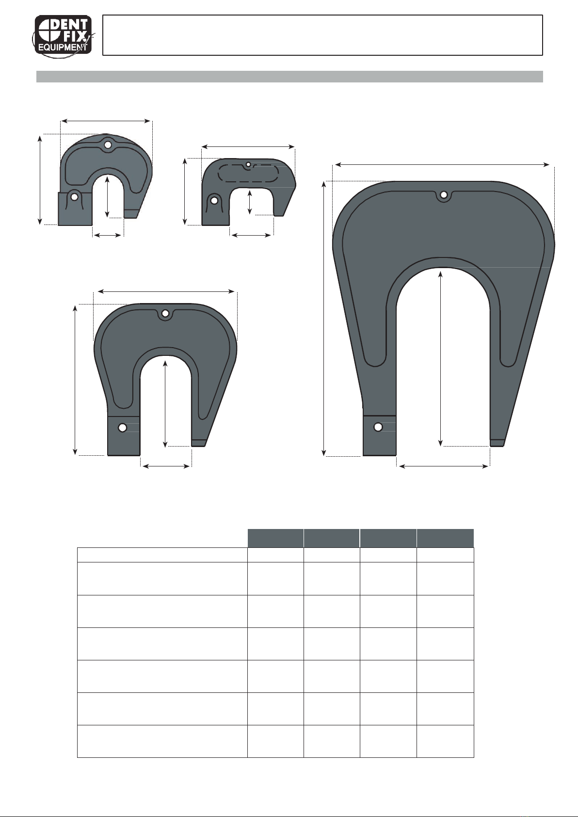
RIVETING ARM / BRAZO DE REMACHADO / NIETBÜGEL / BRAS DE RIVETAGE
HR1
146
HR1S
170
345
50
80
216
80
HR2
147
HR3
!
HR1 HR1S HR2 HR3
Reference / Referencia / Art.-Nr. / Référence -
054219
053878 053885
Length / Longitud / Gesamthöhe / Longueur
150 mm
121 mm
236 mm
390 mm
Width / Anchura / Stärke / Largeur
50 mm
50 mm
50 mm
50 mm
Height / Altura / Gesamtbreite / Altura /
Hauteur
146 mm
170 mm
216 mm
345 mm
Caliper opening / Abertura del brazo /
Öffnungsweite / Ouverture de l’étrier
50 mm
80 mm
80 mm
147 mm
Opening depth / Profundidad de la abertura /
Einstichtiefe / Profondeur de l’ouverture
60 mm
40 mm
130 mm
240 mm
Weight / Peso / Gewicht / Gewicht / Poids
2 kg
2 kg
4 kg
9 kg
150
236
60
130
121
40
390
240
DF-SPR67
EN
5
!
!
This manual contains safety and operating instructions. Read it carefully before using the device for the first time and
keep it in a safe place for future reference.
DESCRIPTION
Thank you for your choice In order to get the maximum benefit from your purchase, please read carefully the following
instructions:
The riveting machine has been especially made for the main types of rivets used and homologated for car body repair:
•Self-piercing rivets
•Flow-form rivets
HANDLING
The correct handling procedures are explained in this user manual. It is vital that the Dent Fix operating procedures are
followed.
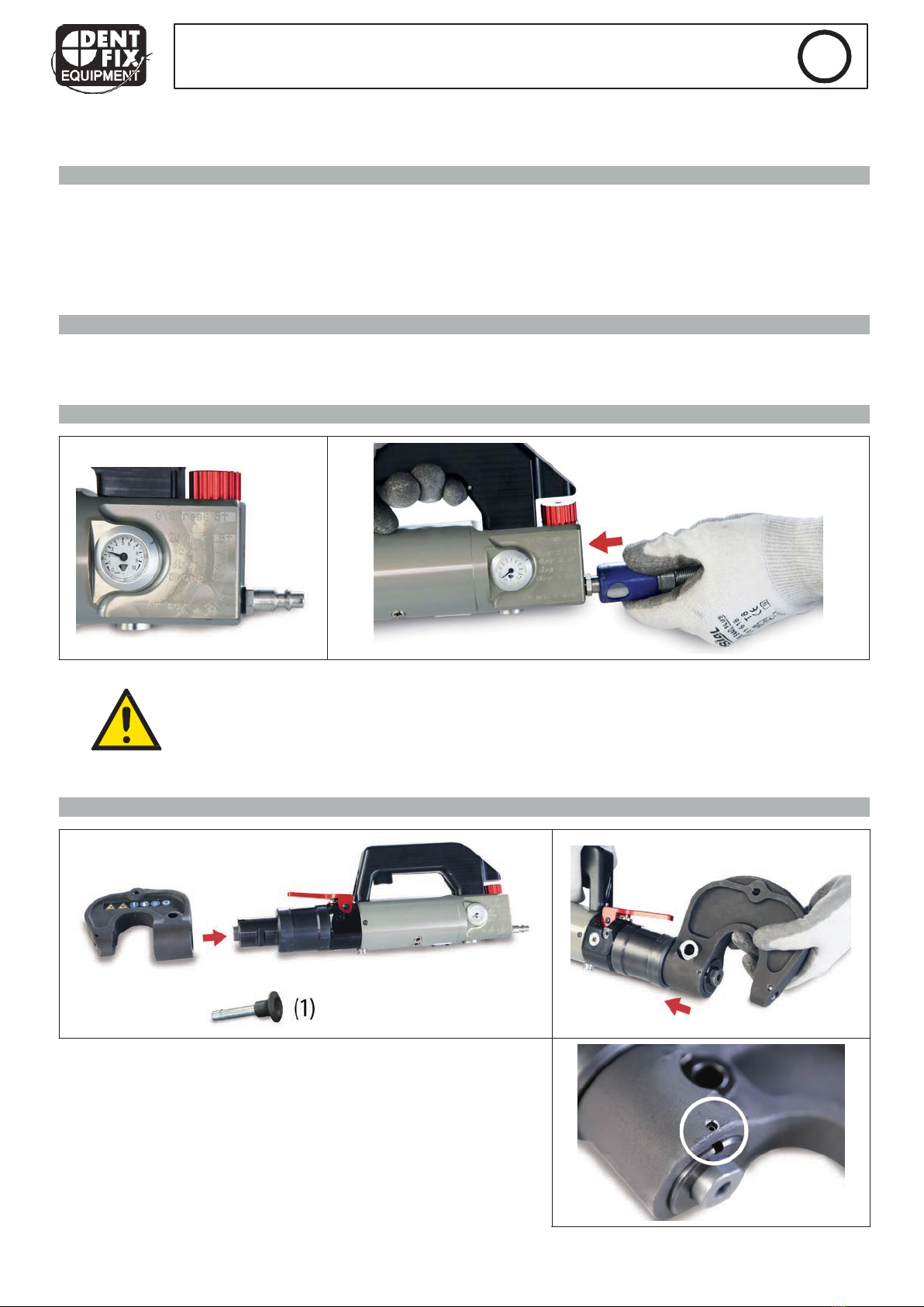
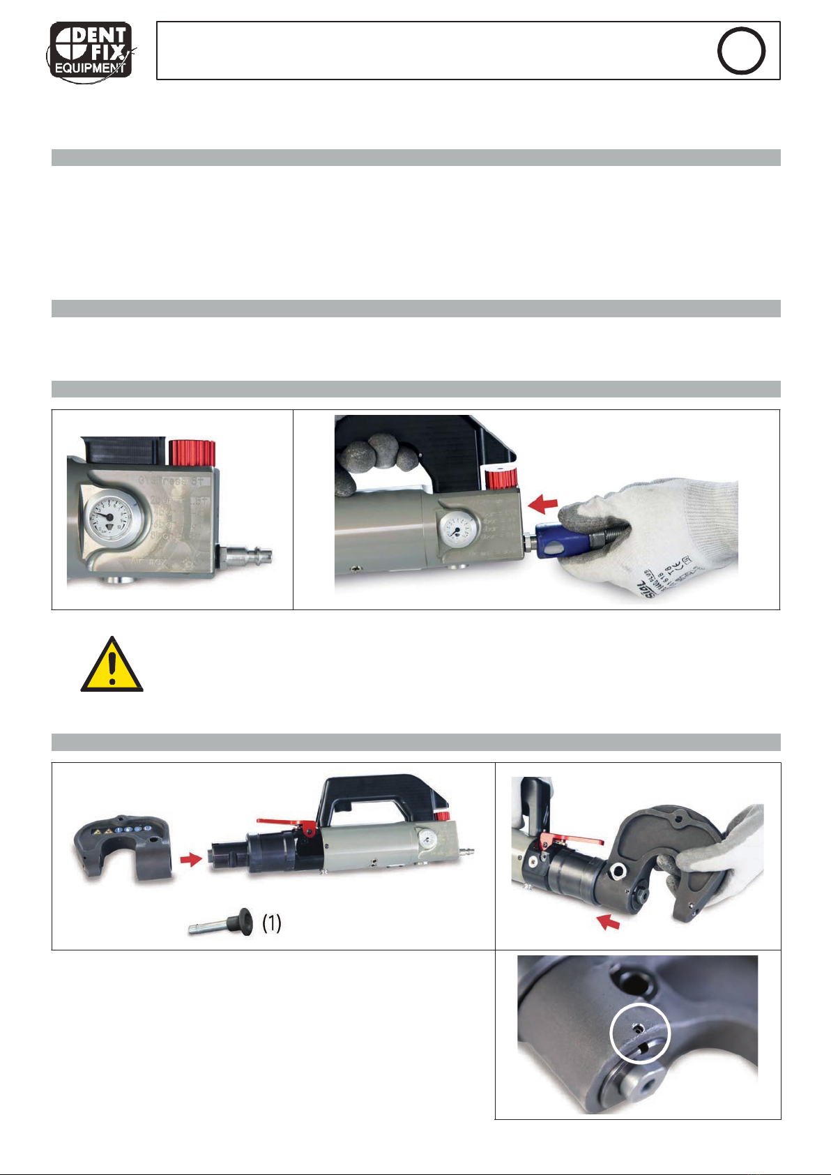
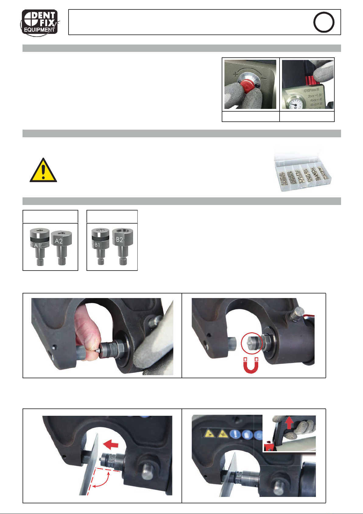
COMPRESSED AIR CONNECTION
Maximum air pressure:
Make sure that the air pressure does not exceed 8 bar.
Clean compressed air:
Make sure you use only clean and dry compressed air for supply the riveting machine. Moisture
and impurities can lead to system failures and/or damages on the product.
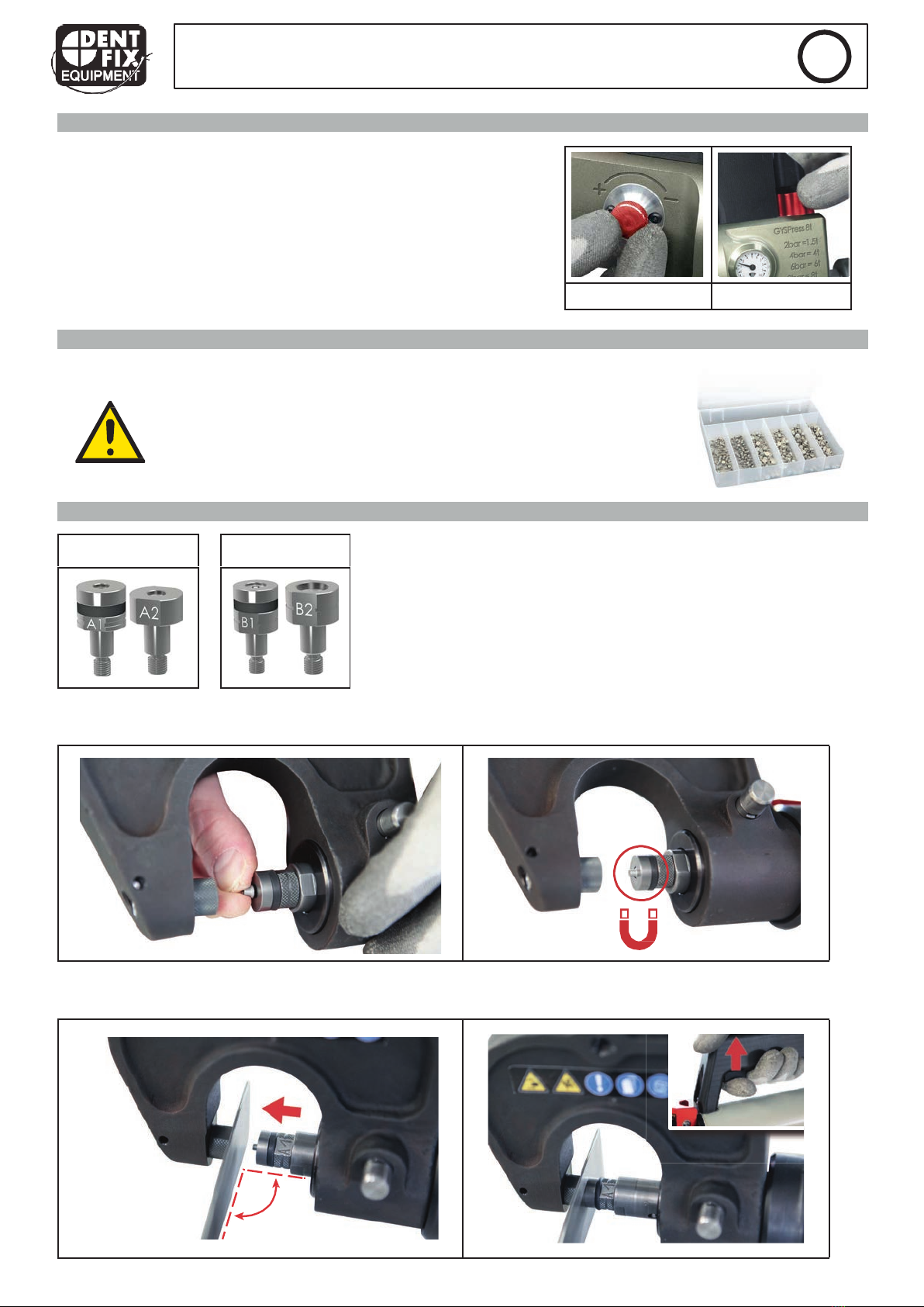
SETTING UP AN ARM
Choose an arm and prepare the locking pin (1). Put the arm with
care on the riveting machine nose, making sure that the 2 points of
reference are aligned.

6
DF-SPR67
EN
!
!
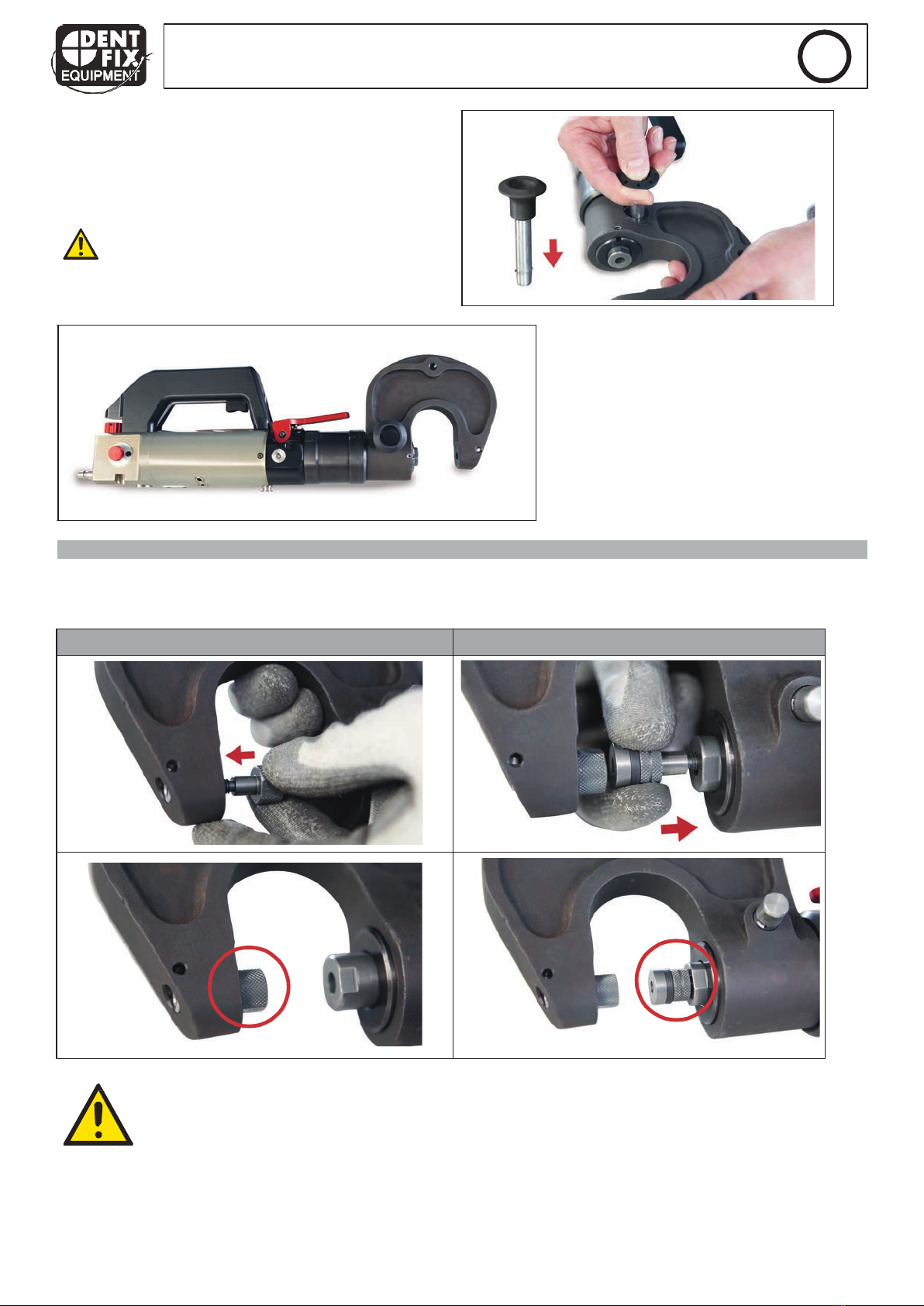
As soon as the arm is on the riveting machine, push the
locking pin in the hole.
The axle locks itself automatically and must not be
allowed to become unlocked.
The locking pin must be clean with no damage. Do
not use any damaged pin.
The riveting machine is now ready to use.
CONNECTOR ASSEMBLY
Screw the required connector kit for the chosen riveting procedure in the arm support. Before assembling, check that
the matrix and the punch support are correctly in place (see page 3) and screwed tight.
Rivet matrix Punch / mandrel support
As soon as the matrix and the punch support are in place, tighten with the spanner
provided. Check that the connection tips are in place after each riveting process. A release is
dangerous and may damage the riveting machine.
7
DF-SPR67
EN
!
!
SPEED AND PRESSURE CONTROL
The user can adjust manually the speed of the actuator as well as
rivet installation pressure according to the type of material in order
to avoid distortion.
See page 30 in order to adjust the pressure according to the
material and matrix.
RIVET BOX INCLUDED
The riveting machine is delivered with a box of 300 self-piercing rivets.
These sample rivets are provided to allow a test of the machine. They are
specific to car body repair.
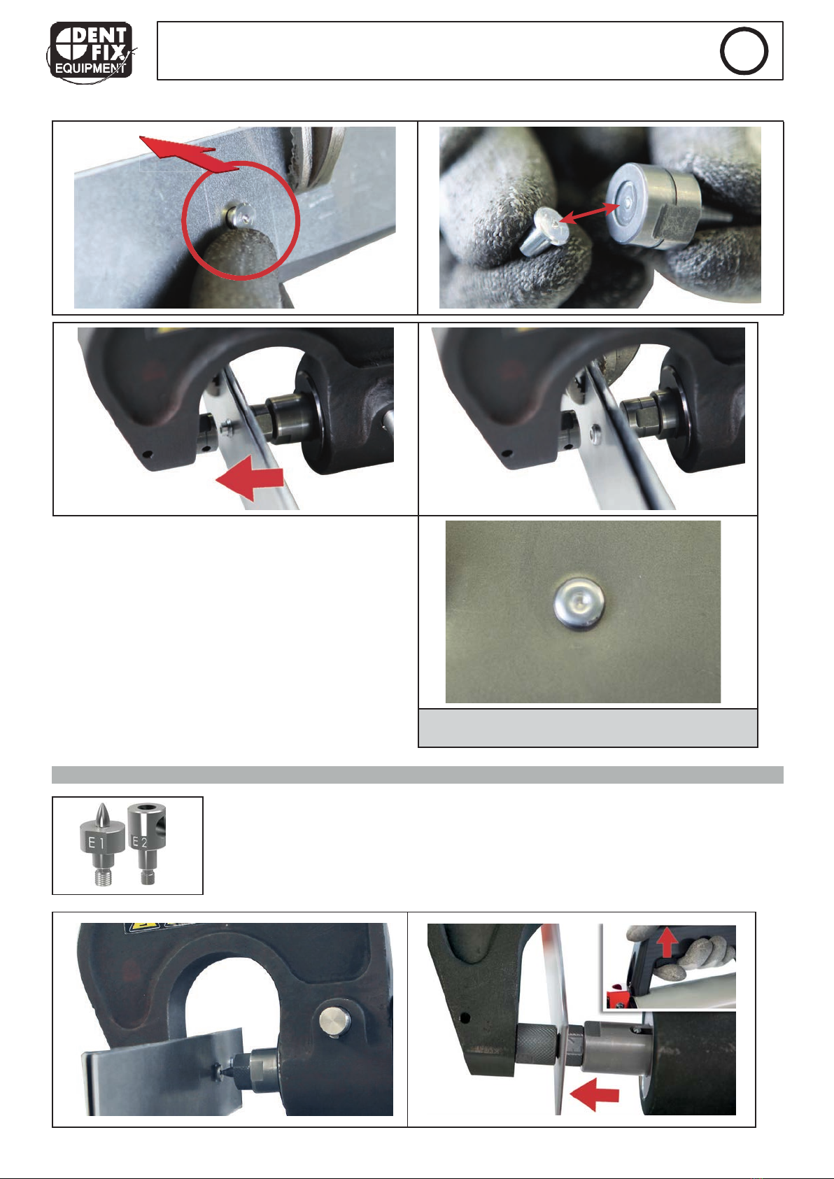
INSTALLATION OF SELF-PIERCING RIVETS
During the installation of self-piercing rivets, make sure that the rivets are well-placed. The matrix must not be damaged
as problems during the riveting process may occur.
During each riveting process, make sure that the matrix - and the rivet itself - are layed out on the metal sheets to
assemble. It is important to put the punch support in place in order to form a 90° angle.
Ø 3,3 mm
Ø 5,3 mm
!"#
!
Speed Pressure
!

8
DF-SPR67
EN
!
!
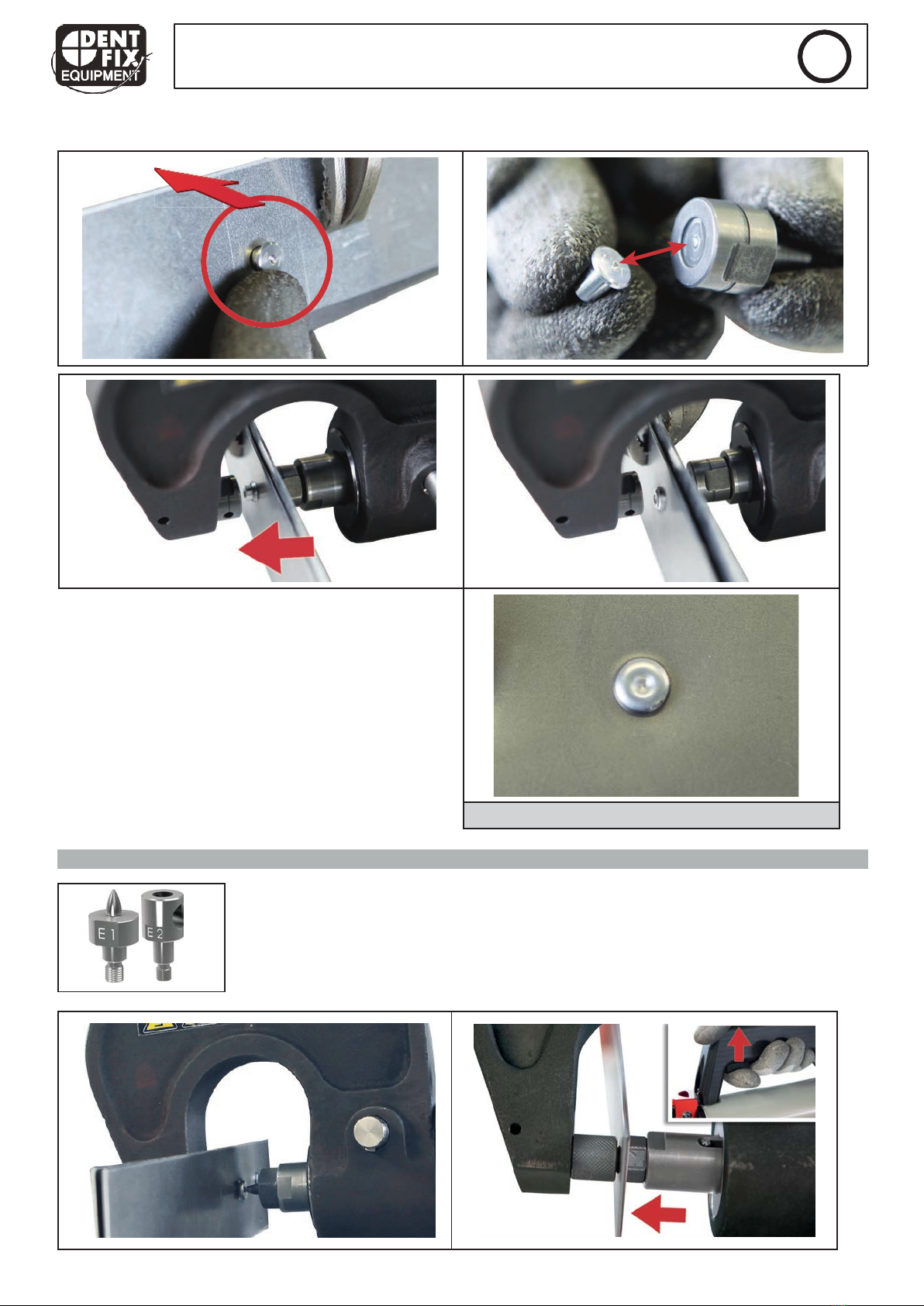
STAMP AND CALIBRATE HOLES FOR FLOW-FORM RIVETS
If using Flow-Form rivets, it is necessary to pre-drill the metal before riveting. The stamping matrix above enables pre-
cise drilling and hole calibration for Flow-Form rivets.
INSTALLATION OF FLOW FORM RIVETS
Before assembling metal sheets with Flow-Form rivets, it is necessary to pre-drill the metal (see
the procedure above).
RESULT OF THE INSTALLATION OF SELF-PIERCING RIVET
After stamping, the punch is pushed into the metal to be
assembled. Then, it is necessary to swing the riveting
machine to release the punch and remove it from the
metal.
9
DF-SPR67
EN
!
!
Once the starter hole is done, insert the Flow-Form rivet: The end piece F1 must be on the head rivet side:
RIVET EXTRACTION
For car body repairs, old or damaged rivets must be removed.
To avoid to have to take off the rivets by drilling, the extraction connection and the matrix
must be used. Indeed, they enable to extract rivets while preserving metal sheets.
RESULT OF THE INSTALLATION OF A FLOW-FORM
RIVET
The F2 matrix has got an evacuation hole for glue resi-
dues. After each use, remove all the glue residues on
the tools.

1
0
DF-SPR67
EN
!
!
Before using the riveting machine and to facilitate the
extraction of self-piercing rivets, it is possible to make
a mark on the rivet with the center punch tool (ref :
048379) to locate the extraction tool in the mark.
If during the extraction, the rivet stay in the matrix
hole, breathe out to get it out before making another
extraction.
CONTROLS AND MAINTENANCE
The DF-SPR67 does not require any special maintenance. A simple periodic visual control is recommended in order to
prevent any breakdown or failure during use.
Clean the DF-SPR67 at least once a week in order to eliminate dust and dirt which could alter the function of the pro-
duct in the long term. Use auto cleaning cloths. Do not use water nor flammable or corrosive liquids.
During maintenance, the compressed air supply must be disconnected.
TROUBLESHOOTING
The chart below indicates the issues that can be observed during the use of the product. If the problem observed
does not appear in the table below, stop using the product and call immediately your distributor to seek support.
SYMPTOMS
POSSIBLE CAUSES
REMEDIES
The riveting machine does not work.
Air is not connected. Connect the air pressure.
Air pressure too low. Check air pressure supply.
The air pressure is not adjusted
correctly.
Adjust air pressure between 2 and 8
bar.
The potentiometer is set at the mini-
mum speed.
Adjust the speed laying.
The rivet is not in place.
Mandrel or matrix faulty Replace the mandrel or the matrix.
Presence of glue on the mandrel or
inside the matrix. Clean the glue
The pressure is not enough. Air pressure is too low or not well-
ajdusted.
Rivet length incorrect. Follow manufacturer instructions.
The piston does not go out or goes
out too slowly. The discharge lever is still blocked. Unblock the discharge lever.
Air, leak.
Faulty pipe. Change the pipe.
Faulty coupling. Change the coupling.
Faulty seals. Repair by the manufacturer.
1
1
DF-SPR67
ES
!
!
Este manual de uso contiene indicaciones sobre el funcionamiento de su herramienta y las precauciones que debe
tomar para su seguridad. Léalo atentamente antes de usar el producto y consérvelo para cualquier consultafutura.
DESCRIPCIÓN
¡Gracias por su elección! Para sacar el máximo provecho de su equipo, lea con atención lo siguiente:
La remachadora ha sido diseñada especialmente para los principales tipos de remaches utilizados y homologados enla
reparación automotriz:
•Remaches autoperforante «Punch Rivets»
•Remaches «Flow Form»
Ideal para todo tipo de operaciones de remachado en chapas (hasta 6,5 mm de grosor).
MANIPULACIÓN
Todas las manipulaciones necesarias para un uso correcto están descritas en este manual. No está permitido utilizar la
herramienta para otros métodos de trabajo que los autorizados por le fabricante.
CONEXIÓN DE AIRE COMPRIMIDO
Presión de aire máxima:
Vigile que la presión de aire máxima no pase de los 8 bar.
Aire comprimido limpio:
Utilice solamente aire comprimido limpio y seco para la remachadora. La humedad y las impure-
zas pueden provocar fallos o daños a la herramienta.
INSTALACIÓN DE UN BRAZO
Elija un brazo y prepare el pasador de bloqueo (1). Coloque el brazo
con precaución en la zona designada para ello prestando atención a
que se alineen las 2 marcas.
1
2
DF-SPR67
ES
!
!
Cuando el brazo esté colocado en la remachadora, intro-
duzca el pasador de bloqueo en el orificio.
El eje se bloquea automáticamente tras su inserción y no
debe salir de nuevo por si mismo del orificio.
El pasador de bloqueo debe estar limpio y exento
de todo daño. No utilice un pasador defectuoso.
La remachadora ya se puede utilizar.
MONTAJE DE LAS BOQUILLAS
Atornille el kit de boquillas necesario para el procedimiento de remachado en el soporte de brazo. Antes de cada mon-
taje, compruebe que la matriz y el soporte para punzón están correctamente asociados (vea página 3) y fijados.
Matriz del remache Soporte para punzón / mandril
Cuando la matriz y el soporte para punzón están instalados, fíjelos con la llave espe-
cial para ello incluida. Compruebe que las boquillas están bien sujetos tras cada remache.
Una pérdida de sujeción es peligroso y puede provocar un deterioro de la remachadora.
DF-SPR67
ES
13
!
!
CONFIGURACIÓN DE LA VELOCIDAD Y DE LA PRESIÓN
El operador puede ajustar manualmente la velocidad de avance del
cilindro y la fuerza de presión del remachado según el tipo de mate-
rial que se vaya a ensamblar para evitar cualquier deformación.
Para ajustar la presión en función de las matrices y mate-
riales, vea la tabla de la página 30.
CAJA DE REMACHES INCLUIDA
La remachadora incluye de fábrica una caja de 300 remaches de acero
autoperforantes. Estos remaches de prueba están incluidos para probar
la remachadora y no se deben usar para la reparación de vehículos.
PONER REMACHES AUTOPERFORANTES
Cuando se vaya a utilizar remaches autoperforantes, controle la base de los remaches. Las matrices no deben estar
dañadas ya que esto podría suponer un problema.
Cuando se proceda a remachar, es imperativo prestar atención a que la matriz, y no el remache, esté colocado sobre la
chapa que se va a ensamblar. Es importante hacerlo de forma que el soporte de punzón esté posicionado sobre la chapa
de modo que forme un ángulo de 90º.
Ø 3,3 mm
Ø 5,3 mm
!"#
!
Velocidad Presión
!

DF-SPR67
ES
14
!
!
PERFORAR Y CALIBRAR LOS AGUJEROS PARA REMACHESFLOW-FORM
Cuando se use remaches Flow-Form, es necesario perforar las chapas anteriormente para permitir la inserción del
remache. La matriz de perforación de la imagen anterior permite una perforación precisa y un calibrado de agujeros
para remaches Flow-Form.
PONER REMACHES FLOW-FORM
Antes de ensamblar las chapas con los remaches Flow-Form, es necesario efectuar un orificio
previo (ver el procedimiento anterior).
RESULTADO AL PONER UN REMACHE AUTOPERFORANTE
Tras la perforación, el punzón se hunde en la chapa que
se va a ensamblar. Tras ello es necesario realizar un
movimiento de retracción con la remachadora para que
el punzón se libere y se retire de la chapa.
DF-SPR67
ES
15
!
!
Una vez que el orificio se ha hecho, inserte el remache
Flow-Form en este:
La boquilla F1 debe estar colocada del lado de la cabeza
del remache:
EXTRACCIÓN DE REMACHES
En caso de reparaciones de chapas de carrocería, los remaches antiguos o defectuosos
deben retirarse de las chapas unidas.
Para evitar retirar estos remaches mediante perforación, se debe utilizar la boquilla de
extracción y su matriz. Estos permiten extraer el remache sin dañar la chapa.
RESULTADO AL PONER UN REMACHE FLOW-FORM
La matriz F2 tiene un orificio de salida para los residuos
de pegamento. Tras cada operación, retire los residuos
de pegamento de las herramientas afectadas.

DF-SPR67
ES
16
!
!
Antes de utilizar la remachadora para facilitar la
extracción de remaches autoperforantes, es posible
hacer una marca en el remache con la herramienta de
punzón de centrado (ref. 048379) para que el punzón
de extracción esté bien centrado en la marca.
Si durante la extracción el remache queda en el orifi-
cio de la matriz, sople para que caiga antes de
realizar
otra extracción.
CONTROL Y MANTENIMIENTO
La remachadora DF-SPR67 no requiere un mantenimiento especial. Se recomienda un simple control visual periódico
para prevenir cualquier fallo eventual durante su uso.
Limpie la remachadora DF-SPR67 al menos una vez por semana para eliminar el polvo y la suciedad que podrían
degradar el buen funcionamiento del producto a largo término. Utilice trapos de usar y tirar. No utilice agua ni líquidos
inflamables o corrosivos.
Cuando se realicen operaciones de mantenimiento, se debe desconectar la entrada de aire compri-
mido del aparato.
ANOMALÍAS, CAUSAS Y SOLUCIONES
La siguiente tabla indica las anomalías que se pueden observar cuando se utiliza esta herramienta. Si el problema
que se ha encontrado no figura en esta tabla, no utilice el producto y contacte inmediatamente a su distribuidor para
conocer qué debe hacer.
ANOMALÍAS CAUSAS SOLUCIONES
La remachadora no funciona.
El aire no está conectado. Conecte el aire comprimido.
No hay aire comprimido. Compruebe la entrada de aire com-
primido.
El aire comprimido no está correcta-
mente ajustado.
Ajuste el aire comprimido entre 2 y
8 bar.
El potenciómetro de velocidad está
ajustado al mínimo. Ajuste la velocidad.
El remache no está colocado correc-
tamente.
Mandril o matriz defectuosos. Reemplace el mandril o la matriz.
Presencia de residuos de pegamento
en el mandril o en la matriz. Limpie el pegamento.
La presión de prensado no es sufi-
ciente.
La presión de aire es demasiado débil
o no está bien ajustada.
Longitud de remache incorrecta.
Respete las instrucciones del
constructor.
El pistón de remachado con dema-
siada lentitud o no sale.
La palanca de descarga está blo-
queada. Desbloquee la palanca de descarga.
Aire, fallo de hermeticidad.
Conducto de aire comprimido defec-
tuoso. Reemplace el conducto de aire.
Fallo del acoplamiento del conducto
de aire. Reemplace el acoplamiento.
Juntas defectuosas. Reparación por el fabricante.

17
DF-SPR67
DE
!
!
Diese Betriebsanleitung enthält Sicherheits- und Betriebshinweise. Bitte lesen Sie diese Anleitung aufmerksam durch,
bevor Sie das Gerät zum ersten Mal benutzen und bewahren Sie sie sorgfältig auf.
BESCHREIBUNG
Wir freuen uns, dass Sie sich für ein Markengerät der Firma Dent Fix entschieden haben, und danken Ihnen für das
entgegengebrachte Vertrauen. Um das Gerät optimal nutzen zu können, lesen Sie bitte die Betriebsanleitung sorgfältig
durch.
Das Nietgerät wurde für die Applikation diverser in der Karosseriereparatur zu verarbeitenden und freigegebenen Niet-
typen konzipiert und eignet sich für VErnietungen an Blechen bis 6,5 mm Gesamtblechstärke.
-Stanzniete "Punch Rivets"
-Fließformniete "Flow Form"
HANDHABUNG
Alle für einen störungsfreien Betrieb relevanten Handhabungen sind in dieser Betriebsanleitung beschrieben. Vom Hers-
teller Dent Fix nicht autorisierte Anwendungen sind untersagt.
DRUCKLUFTANSCHLUSS
Maximaler Betriebsdruck:
Der Betriebsdruck darf 8 bar nicht überschreiten.
Saubere Druckluft:
Die Druckluft zur Versorgung des Nietgerätes sollte sauber und trocken sein. Feuchtigkeit und
Verschmutzungen können den Betrieb stören und das Gerät beschädigen.
NIETBÜGEL-MONTAGE
Nietbügel auswählen und Arretierstift bereit legen(1). Bügel ohne ver-
kanten sorgfältig aufsetzen und die beiden Markierungen in Übereins-
timmung bringen.

18
DF-SPR67
DE
!
!
Nach Aufsetzen des Nietbügels, den Arretierstift in die
Bohrung einsetzen.
Der Arretierstift muss zur Arretierung bis über die
Kugelsperre eingeschoben werden.
Der Arretierstift muss sauber und unbeschädigt
sein. Keinen beschädigten Arretierstift benutzen.
Das Nietgerät ist betriebsbereit.
NIETWERKZEUG-MONTAGE
Das für den Niet-/ Entnietvorgang passende Werkzeug in den Träger des Bügels einschrauben. Vor der Montage,
sicherstellen, dass Matrize und Locheisenträger zueinander passen (s. Seite 3) und festgezogen sind.
Nietmatrize Gegenstempel
Nietmatrizen und Werkzeuge müssen in jedem Fall komplett eingeschraubt, korrekt
montiert und mit dem beiligenden Schlüssel fest gezogen werden. Stellen Sie nach
jedem Nietvorgang sicher, dass sich die Werkzeuge nicht gelöst haben. Nicht korrekt sitzende
Werkzeuge können das Gerät beschädigen.

29
DF-SPR67
!
!
WARRANTY CONDITIONS
-The warranty covers faulty workmanship for one year from the date of purchase (parts and labour). - The warranty
does not cover incidents due to misuse, fall, disassembly or other damage due to transportation. - The warranty does
not cover normal wear of parts. Only the spare parts provided by Dent Fix should be used to perform repairs on the
riveting machine DF-SPR67.
In case of failure, return the unit to Dent Fix including:
-The proof of purchase (dated bill, ticket ...)
-An explanatory note of the failure.
CONDICIONES DE GARANTÍA
La garantía cubre todo defecto o vicio de fabricación durante un año, a contar a partir de la fecha de compra (piezas y
mano de obra). La garantía no cubre incidentes debidos al mal uso, caída, desmontado o toda avería debida al trans-
porte. La garantía no cubre el desgaste normal de las piezas. Se deben utilizar solamente las piezas de recambio de
Dent Fix para realizar una reparación de la remachadora DF-SPR67.
En caso de fallo, devuelva la herramienta a la empresa Dent Fix añadiendo:
-un justificante de compra (ticket de caja, factura...).
-una nota explicativa del fallo.
GARANTIE
Die Garantieleistung erfolgt ausschließlich bei Fabrikations- oder Materialfehlern, die binnen 12 Monate nach Kauf
angezeigt werden (Nachweis Kaufbeleg). Nach Anerkenntnis des Garantieanspruchs durch den Hersteller bzw. seines
Beauftragten erfolgen eine für den Käufer kostenlose Reparatur und ein kostenloser Ersatz von Ersatzteilen.
Ausschluss:
Die Garantieleistung erfolgt nicht bei Defekten, die durch unsachgemäßen Gebrauch, Sturz oder harte Stöße sowie
durch nicht autorisierte Reparaturen oder durch Transportschäden, die infolge des Einsendens zur Reparatur, hervor-
gerufen worden sind. Keine Garantie wird für Verschleißteile (z. B. Kabel, Klemmen, Vorsatzscheiben etc.) sowie bei
Gebrauchsspuren übernommen.
Nur Ersatzteile von Dent Fix dürfen bei Reparaturen vom Nietgerät DF-SPR67 benutzt werden.
Das betreffende Gerät bitte immer mit Kaufbeleg und kurzer Fehlerbeschreibung ausschließlich an Dent Fix einschicken.
Kontakt KD:
Dent Fix
CONDITIONS DE GARANTIE
La garantie couvre tout défaut ou vice de fabrication pendant 1 an, à compter de la date d’achat (pièces et main
d’œuvre). La garantie exclut les incidents dus à un mauvais usage, chute, démontage ou toute autre avarie due au
transport. La garantie ne couvre pas l’usure normale des pièces. Seules les pièces de rechange provenant de chez Dent
Fix doivent être utilisées pour effectuer une réparation sur la riveteuseDF-SPR67.
En cas de panne, retournez l’outil à la société Dent Fix, en y joignant :
-un justificatif d’achat (ticket de caisse, facture…)
-une note explicative de la panne.
30
!
!
V\!
!
Q\!
!
O\!
!
J\!
!
F\!
!
B\!
!
!
!
!
!"#
!
$%&
!
!''
!
"()
b!BcB!..!
!
!
*()
b!JcB!..!
$(!
!
!
!
+(
!
!
!
'(
!
!
!
(
!
,
!
()
-)
,)
-)
.
!
.
!
!
!
",)
b!BcB!..!
!
!
*,)
b!JcB!..!
!
!
!
$,!
!
!
+,
!
!
!
',
!
!
!
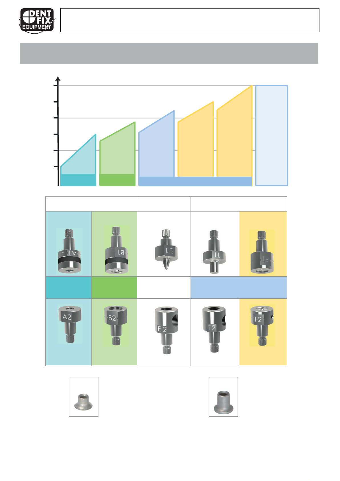
-Self-piercing rivets (SPR)
-Remaches autoperforantes
-Stanznieten
-Rivets Auto-Perçants
-Flow-Form rivets (FFR)
-Remaches Flow-Form
-Fließformniete
-Rivets Flow-Form
DF-SPR67
PRESSURE CONTROL CHART / TABLA DE AJUSTE DE PRESIÓN TABLA DE AJUSTE DE PRESIÓN/
TABELLE EINSTELLUNG PRESSDRUCK / TABLEAU RÉGLAGE PRESSION
JcVd/
!
JcBd012
!
FcQd314
!
$5$6+!
%
)
&!78879:
!
N#!
OcJd4
!
4
!
Bd31,
!
!"#
!
;).1.
!
1
!"#
!
;)31.
!
2
!''
!
"8<
)
;)0
!
!''
!
=+$$8)
;)0
!
!''
!
=+$$8)
;)4
!
3
RAP RFF
Table of contents
Popular Rivet Tools manuals by other brands


Stanley
Stanley PROSET PB2500 instruction manual

Beta
Beta 1946C 7,8 instructions

FAR
FAR RAC 3000 TRANSLATION OF ORIGINAL INSTRUCTIONS

Gesipa
Gesipa PH 2000 Operating manual with spare parts list

Gesipa
Gesipa PowerBird Pro Gold Edition Operating manual with spare parts list

Scell-it
Scell-it ESSENTIAL E-312NP Operation manual


