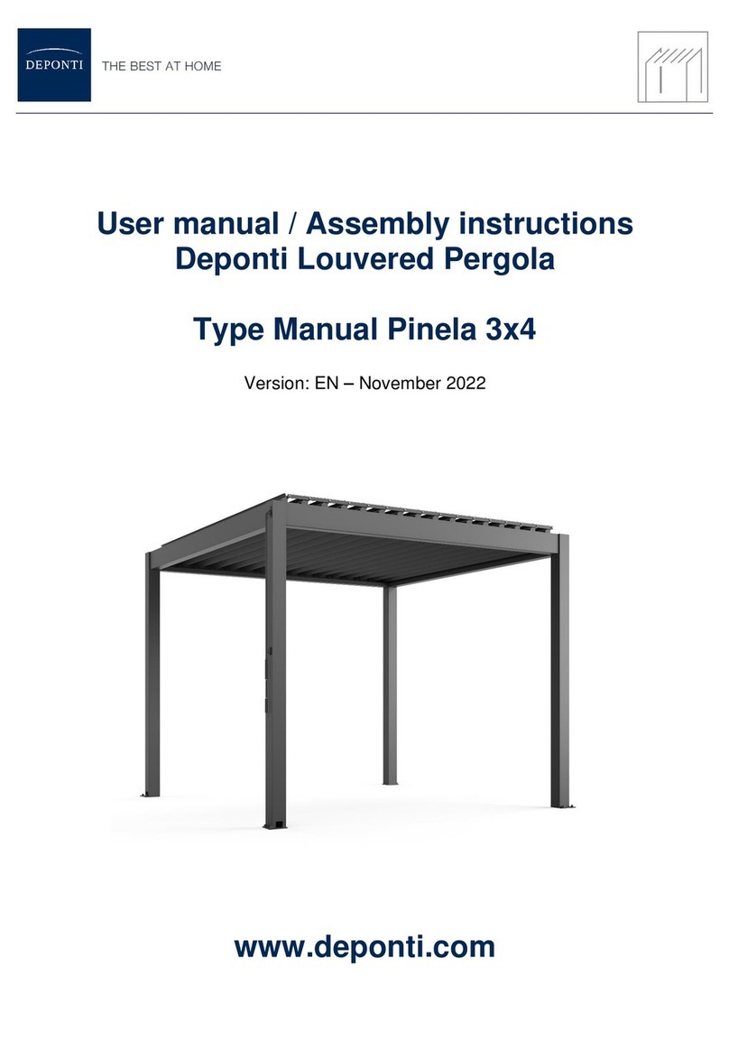
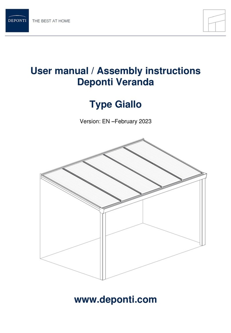
Deponti Verdeca User manual

User manual / Assembly instructions
Deponti Retractable Roof Pergola
Type Verdeca
Version: EN –September 2020
www.deponti.com

www.deponti.com Assembly Manual –Verdeca Pergola page
2
Contents
1. Introduction 3
2. Safety precautions and warnings 3
3. Product features 5
4. Parts overview 6
4.1 Exploded view 6
4.2 Motorization 7
4.3 Hardware details 7
4.4 Delivery inspection 10
5. Preparation for assembly 11
5.1 Conditions for assembly 11
5.2 Inspection of tools and accessories 12
6. Assembly 13
6.1 Structure installation 13
6.2 Installation motor unit and fabric 17
6.3 Installation of cross rafters and ceiling sheets 20
7. Programming instructions 22
7.1 Remote control 23
7.2 Programming the motor 24
7.3 Resetting the motor 24
7.4 Programming the LED control panel 25
7.5 Resetting the LED control panel 25
8. FAQ 26
9. Maintenance 26
10. Disposal of waste 26
11. Warranty conditions 27
12. Contact 27
KEEP THIS MANUAL IN A SAFE PLACE FOR FUTURE USE!
For the duration and the terms and conditions of the warranty we recommend that you contact your supplier. We
also refer you to our General Terms and Conditions of Sale and Delivery which are available on request. Deponti
B.V. accepts no liability for any damage or injury resulting from a failure to carefully follow the instructions in this
manual or exercise due caution during transport, assembly, use and maintenance of the Pergola. As a result of
our policy of continuous product improvement, certain product details may differ from what is described in this
manual. For this reason the instructions provided only serve as a guideline for installation of the product this
manual describes. This manual has been compiled with the utmost care, but Deponti B.V. cannot be held
responsible for any errors in this manual or the consequences thereof. Furthermore, all rights are reserved and no
part of this manual may be reproduced in any way whatsoever.

www.deponti.com Assembly Manual –Verdeca Pergola page
3
MANUAL
LEES
AANDACHTIG
!
!
1. Introduction
Congratulations on the purchase of your Deponti Pergola!
Before you can start enjoying your Pergola it must be assembled properly. This manual provides clear
instructions for all the steps you must complete for correct assembly of your Deponti Pergola. We
recommend that you take the time to read the entire manual before you begin assembly.
Check whether you have received all the necessary parts before you begin assembly. For your safety,
follow all the applicable instructions. This also guarantees the safety of the installed roof. If you
should have any questions, please feel free to contact your Deponti representative.
This manual should be kept in a safe, dry and shady place. In the event of damage or loss, the user
must request a new copy of the manual from the Deponti representative.
2. Safety precautions and warnings
Important:
Please read the safety precautions and warnings before assembling the pergola.
•During assembly, carefully follow the instructions and guidelines as described in this manual.
Never change the order of the steps to be performed. If any aspect of the assembly
procedure is unclear, please contact your Deponti representative. We reserve the right to
make technical changes without written notice.
•We normally recommend that the pergola must be assembled by at least two
people (qualified technicians/authorized installers) working together.
•Check the delivery immediately upon receipt. In the event of damage or an incomplete
delivery please contact your representative immediately.
•The materials must be stored in a dry, ventilated area, not exposed to direct sunlight.
•Open the packaging carefully. Make sure that you do not damage the product.
•To prevent damage to your pergola, place the parts on a smooth, clean surface. Place the
profiles on a flat surface, protected from sun and rain.
READ
CAREFULLY

www.deponti.com Assembly Manual –Verdeca Pergola page
4
2. Safety precautions and warnings (continued)
•Adding or removing parts, the use or installation of materials. other than described in this
manual, may adversely affect the safety of the pergola and is therefore strongly discouraged!
•Pay attention and be aware of moving parts. Make sure that all power supply is cut off during
the assembly.
•Cordon off the assembly location so that others are kept at a safe distance.
•Always wear the correct protective clothing (work gloves, dust mask, safety glasses, shoes
with non-slip soles, etc.) during installation or servicing.
•Mount the system against a firm, flat wall and on a flat and stable foundation. Ensure that
the wall and the ground are clean and dry.
•You must maintain and clean your pergola at least once a year. During this yearly
maintenance make sure all fasteners are properly tightened.
•Dispose the product in accordance with local laws and regulations.
•When safety regulations and instructions are not followed correctly, Deponti B.V. will not
accept any responsibility for damage(s) and injuries.

www.deponti.com Assembly Manual –Verdeca Pergola page
5
3. Product features
The Verdeca Pergola is a retractable system which has a tilted form. It consists of an aluminium
structure and fabric. This product requires a minimum slope value due to its characteristic feature
and healthy drainage.
•The Verdeca is water and airproof. It protects against sun and rain.
•Wind resistance is 11 Beaufort by all sides open and 7 Beaufort by side enclosure.
Calculated for products with a front height of 250 cm according to Eurocode EN 1991-1-4
Terrain Category 4.
•This system has limited snow load capacity which is 15 kg/m² therefore it should always be in
retracted position if snow is expected or it start snowing.
•The fabric is made from exclusive fabric manufactured by Sioen. It is supported by fabric
profiles.
•The belts are installed into each rail and driven by pulleys and single drive shafts to ensure
fabric movement.
•The Verdeca Pergola retractable system is operated by an electric motor via a radio control
transmitter.
Available dimensions of the Verdeca:
Width (mm): 4000 / 5000 / 6000
Projection(mm): 3000 / 3500 / 4000
This product requires a min. slope value due to its characteristic feature and healthy drainage. The
slope value depends on the product dimensions.
Below table is showing the minimum slope values [cm] for all available dimensions.
If the Deponti Pergola Verdeca is installed with a slope of > 25% the product will be out of warranty.
*Optional: built-in LED lighting in the fabric
Application type:
The Verdeca has a retractable system with a tilted form and has to be mounted to a wall.
With a single motor opening and closing of the roof is motorized and controlled by a remote control
Minimum slope [cm]:
3000 3500 4000
Width [mm] Rail centre [cm]
4000 400 42 49 57
5000 250 26 30 35
6000 300 31 37 42
Projection [mm]
!

www.deponti.com Assembly Manual –Verdeca Pergola page
6
4. Parts Overview
4.1 Exploded view
1 Wall profile 5 Motor unit
2 Post 6 Fabric
3 Gutter 7 Cross rafter
4 Rafter 8 Side cover profiles, ceiling sheets and wall finish profile

www.deponti.com Assembly Manual –Verdeca Pergola page
7
4.2 Motorization
The Verdeca pergola is using a single motor from Somfy type OREA 60 RTS 55/17.
The motor is controlled and operated by a remote control. The Somfy Telis 4 RTS remote is provided.
4.3 Hardware details
Rafter - Wall profile connection
a. M8x16mm hexagonal head stainless steel bolt
b. M8 stainless steel washer
c. M8 stainless steel nut
Rafter - Gutter connection

www.deponti.com Assembly Manual –Verdeca Pergola page
8
Post –Gutter connection
Pillar –Ground connection
Use materials suitable for your situation.
Motor unit –Wall profile connection
a. M5.5x25mm self-drilling screw with washer

www.deponti.com Assembly Manual –Verdeca Pergola page
9
Fabric –Carrier (rafter) connection
M8 nut with sealant
Cross rafter –Rafter connection
a. M4.8x25mm self-drilling screw (3x)
b. M4.8x25mm self-drilling screw (6x)

www.deponti.com Assembly Manual –Verdeca Pergola page
10
Fabric cover sheet –Cross beam connection
a. M5. 5x25mm self-drilling screw with washer
4.4 Delivery Inspection
Always carefully check the delivered items against the accompanying delivery note to ensure that the
quantity and quality are correct. Any visible defects must be reported in writing within 7 days of
delivery.
Note:
• Boxes with red label: Electronic parts like Control Unit Box, Remote Controls.
• Boxes with blue label: Metal parts like U Brackets, Mounting brackets, Gutter caps, screws.
• Boxes with yellow label: Plastic parts like Rubber for the gutter, caps, motor shaft drive transmitter.

www.deponti.com Assembly Manual –Verdeca Pergola page
11
5. Preperation for assembly
5.1 Conditions for assembly
Ground & wall
•A good flat stable surface is required for construction of the pergola.
•The location where the system is placed must be construction-ready and free of obstacles
(garden furniture, flower boxes, etc.) so installers can perform their work without hindrance.
•Any obstacles, including utility lines (such as power cables, etc.), roots and debris, must have
been removed from the ground.
•The wall must be free of sun shades, etc.
•The area where the wall profile will be placed must be firm, even and flat.
Attachments at walls
•Due to expansion of the materials, the pergola may not be placed tightly between two walls;
there must be a gap of 1.5 mm per metre of width of the pergola.
Rubber seals
•A Deponti pergola is standard equipped with pre-assembled rubber seals.
•If the rubber seals are deformed, they can be straightened with a little heat, from a hot air
heater or hair dryer for example.
Remove protective film
•It is recommended that the protective film be removed from the aluminium parts at the last
possible moment, to prevent damage. When mounting the different parts, however, the
edges of the protective film must be pulled back a few centimetres towards the middle of the
sheet so the film does not get stuck in the profiles; otherwise it will be difficult to remove
later.
Warranty expires if the Verdeca Pergola is not assembled and installed in accordance with
the instructions.

www.deponti.com Assembly Manual –Verdeca Pergola page
12
5.2 Inspection of tools and accessories
)
Ø16
13, 17

www.deponti.com Assembly Manual –Verdeca Pergola page
13
6. Assembly
6.1 Structure installation
1. Wall bracket installation:
The wall brackets must be installed 35cm from the end of the rails.
2. Fasten the brackets to the wall/ Use the correct hardware for your situation. We suggest
to use minimum M12.
3. Install the wall profile on the wall mounting brackets.
NOTE: Don’t work alone. You may need someone else while placing of the back profile.
H [cm] = front height [cm] + slope [cm]
Standard front height is 250 cm

www.deponti.com Assembly Manual –Verdeca Pergola page
14
4. Fasten and tighten the wall mounting bracket bolts
5. Gutter and front posts:
The gutter and front posts should be connected to each other on ground

www.deponti.com Assembly Manual –Verdeca Pergola page
15
6. Post fixing:
Define the exact post position and mark it. Install the anchorage to the ground surface using
correct hardware for your situation.
before you lift as you shown image at below. In this situation you may need some people
since you must hold to posts as carefully.
7. Slide the post on top of the stainless steel anchorage and screw tight.

www.deponti.com Assembly Manual –Verdeca Pergola page
16
8. Slide the rubber flap in and place gutter cover and fasten the screws.
9. Rafter placing: There are two types of rafters. One without gasket (only delivered if 3
posts are used –width exceed 4.5 m) and two with gasket (this is located on the bottom of
the rail). When you look from the front side, the gasket must be inside of the system as you
see at below picture.
NOTE: When fastening the rail bolts to the back beam and front beam you might need
someone else according to rail weight and length.
10. Check if the structure is level on all sides.
Deponti
Deponti
Deponti

www.deponti.com Assembly Manual –Verdeca Pergola page
17
6.2 Installation motor unit and fabric
1. Install the motor box in the centre between two rafters.
2. All carriers must be on the back of the rails.
3. Place a hexagonal shaft spindle into the transmission tube.

www.deponti.com Assembly Manual –Verdeca Pergola page
18
4. Place the hexagonal shaft spindle and transmission tube into the motor as you see on the
fifure below.
5. Insert a shaft transmitter plastic on to the transmission tube on the inside of the system.
6. Place a shaft spindle through the rail and insert the shaft transmitter plastic on the spindle
to connect to the other spindle.

www.deponti.com Assembly Manual –Verdeca Pergola page
19
7. Fasten the bolts on the shaft transmitter plastic caps.
8. Install the fabric support profiles with the fabric preinstalled on to the rafters. The fabric
support profiles go rafter by rafter onto the carriers. They slide over the thread on the
bottom of the carriers in place with the nuts. While installing the fabric, you must fasten the
nuts simultaneously on the fabric support profiles.
NOTE: While installing the bolts, the gaskets are compressed to create a whole thigth seal.
Getting the nuts on could therefore be a challenge.
NOTE: We recommend using a lift or miltiple persons for installation as the fabric needs to
go up as a whole without damage.

www.deponti.com Assembly Manual –Verdeca Pergola page
20
6.3 Installation of cross rafter and ceiling sheets
1. Start with installing the cross rafters: In order to fix the cross rafters, you should define
the U bracket position. First you have to check the retractable length of the fabric is within
the length of the side cover profile, if correct you can install the U brackets according to that
sizing.
2. OPTIONAL: You can install the optional LED control box to the cross beam.
Table of contents
Other Deponti Outdoor Furnishing manuals
Popular Outdoor Furnishing manuals by other brands
Home Decorators Collection
Home Decorators Collection ARTIS FCA65075L-BLK Assembly instructions

U-Line
U-Line H-2671 Assembly instructions

Creative Play
Creative Play CP008/OCT Assembly instructions

Blumfeldt
Blumfeldt 10031458 manual

Broyhill
Broyhill A206005302 Assembly instructions

Marquee
Marquee ORIENTAL LEAN TO WALL GAZEBO Assembly instructions