manuals.online logo
Brands
  1. Home
  2. •
  3. Brands
  4. •
  5. Desa
  6. •
  7. Fireplace Accessories
  8. •
  9. Desa Comfort Glow GA3750 User manual

Desa Comfort Glow GA3750 User manual

Parts included with this kit:
Part No. Description Quantity
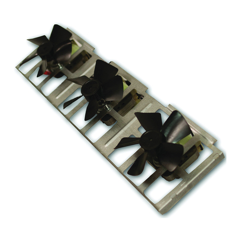
Blower with speed control and 6-foot cord. 1
Instruction Sheet 1
103649-01 Mounting Hardware Kit (includes all parts below)
103650-01 Control Knob 1
103651-01 Lock Nut 1
M11084-38 #8 x 3/8" sheet metal screws 4
101629-01 Plastic Hole Bushings 2
101584-05 Wiring Diagram Decal 1
Tools Required
• Pliers
• Phillips Screwdriver
If any of these pieces are missing or damaged, or if the installation instructions for your
fireplace or stove are not included in this manual, contact the dealer where you purchased
this kit or DESA International at 1-800-972-7879 for referral information.
INSTALLATION INSTRUCTIONS FOR
GA3750 BLOWER ACCESSORY
Note:
ThisblowerkitshouldbeusedwithComfortGlowmodelCGFB32C
orCGFB36CSeriesfireboxes;ormodelCGFP28N,CGFP28P,CGFP28NT,
CGFP28PT, LFP33NR, LFP33PR Series fireplaces; or model CDV or
CHDV Series Comfort Glow direct vent fireplaces.
2
103964
2. Place the blower against lower rearwall
of firebox wrapper with the exhaust
port directed upward. Align the holes
in top mounting tabs of blower with
holes in wall of wrapper (see Figure 2).
Using2screwsprovided,mount blower
and tighten screws securely.
3. Be certain that all wire terminals are
securely attached to terminals on
blower motor and that the screw retain-
ing the green ground wire is tight.
4. Locate the plastic hole plug installed
in the 3/8" diameter opening in the
lower right side of the firebox front
panel (see Figure 2). Remove the plas-
tic plug and discard.
5. Place speed control against inner wall
of front panel, pushing the plastic con-
trol shaft forward through the opening
(see Figure 3).
6. While supporting speed control, secure
control shaft with lock nut by pushing
Installing GA3750 Blower Accessory in
Comfort Glow Model CGFB32C Series Firebox
9. Check to make sure that the powercord
is completely clear of the blower wheel
and that there are no other foreign ob-
jects in blower wheel. Turn blower on
and check for operation.
Figure 1 - Removing Screws from Fire-
box Bottom
and turning lock nut with pliers clock-
wise until it is tight against front panel.
Place control knob provided on shaft
(see Figure 3).
7. Plug in blower power cord.
a. Ifyourfireboxisinstalled as afree-
standing unit, determine whether
the power cord will exit the left side
or the right side of the firebox. In-
stall 1 plastic bushing provided into
the 1 1/2" hole in the floor support on
the exit side. Install the second plas-
tic bushing provided into the 1 1/2"
hole in the outer casing through
which the power cord will exit (see
Figure 4). Route power cord through
both plastic bushings and plug the
power cord into a 3-prong grounded
wall receptacle near the firebox.
b.If your firebox installation is re-
cessed and/or pre-wired, plug the
power cord into the duplex outlet
provided. Refer to your firebox
owner’s manual for instructions on
wiring the duplex outlet.
8. Turn on power to duplex outlet if pre-
viously turned off per the warning in
step 1.
Figure 4 - Installing Plastic Bushing for
Power Cord
NOTICE: If a log set is currently
installed in the firebox, discon-
nect log set from gas supply and
remove from firebox. Contact a
qualifiedservicepersontodothis.
1. Remove the firebox bottom:
a. Remove the 4 screws that secure the
bottom of the firebox (see Figure 1).
b.Carefully raise and remove the fire-
box bottom from the firebox.
WARNING: Ifthe duplex elec-
trical outlet installed in the right
sideofthebottomofthefireplace
base area is wired to a electrical
power source, be sure that the
electrical power to the outlet is
turnedoffbeforeproceedingwith
blower installation. Failure to do
this may result in serious injury.
Screws
Blower
Plastic
Hole Plug
Lower
Rear Wall
of Firebox
Floor
Supports
Exhaust Port
WARNING: Never touch the
blower wheel while in operation.
10. Peel off the backing paper and stick the
suppliedwiringdiagramdecalonthefire-
box bottom approximately 12" in front
of the blower (see Figure 13, page 5).
11. Replacebottom offirebox.
Note:
Make
sure the back of the firebox bottom
slidesunder the rear of thefirebrick (lift
the firebrick up if necessary.)
12. Reattach firebox bottom using 4 screws
removed in step 1.
Note:
Discard the remaining hardware
items.
13. Install the log set heater according to
the installation instructions supplied
with the heater.
NOTICE: A qualified service per-
son must install heater. Follow
all local codes.
Operating the Blower
Light your gas appliance with the blower
off.After about 15 minutes, turn the blower
on to deliver heated air at the top louvers.
Theblowerfeaturesavariablecontrolwhich
allows you to select the speed you desire.
Note:
Periodically check the louvers of the
firebox and remove any dust, dirt, or other
obstructions.
Screws
Figure 2 - Mounting Blower to Firebox
Top
Mounting
Tab
Plastic
Bushing
Figure 3 - Attaching Speed Control
Speed
Control
Lock Nut
Control Knob
Control
Shaft
3
103964
IMPORTANT:
For clarity, gas valve as-
sembly, logset, and grate/burner assembly
are not shown in Figures 5 through 8. They
will be in your fireplace when you are in-
stalling the blower.
1. Open lower louver panel.
2. Place the blower against the lower rear
wall of firebox outer wrapper with the
exhaustport directed upward.Alignthe
holes in the top mounting tabs of
blower with holes in wall of wrapper
(see Figure 5). Using the two screws
provided, mount blower and tighten
screws securely.
3. Be certain that all wire terminals are
securely attached to terminals on
blower motor and that the screw retain-
ing the green ground wire is tight.
WARNING: Never touch the
blower wheel while in operation.
10. Peel off the backing paper and stick the
suppliedwiringdiagramdecalonthefire-
boxbottomapproximately 3" totheright
of the blower speed control (Figure 8).
WARNING:Failuretoposition
thepartsinaccordancewithsup-
plied diagrams or failure to use
only parts specifically approved
withthisheatermayresultindam-
age or personal injury.
11. Connect gas supply to fireplace per in-
structionsinoperating manual provided
with fireplace.
NOTICE: A qualified service per-
son must connect fireplace to
gassupply.Followalllocalcodes.
Operating the Blower
Light your gas appliance with the blower
off.After about 15 minutes, turn the blower
on to deliver heated air at the top louvers.
Theblowerfeaturesavariablecontrolwhich
allows you to select the speed you desire.
Note:
Periodically check the louvers of the
firebox and remove any dust, dirt, or other
obstructions.
NOTICE:Shutoff gassupplyand
disconnect heater from gas sup-
ply. Contact a qualified service
person to do this.
4. Remove screws securing the plate con-
taining the ON/OFF switch to the bot-
tom of the firebox and set aside.
5. Place speed control against back of this
plate and push the plastic control shaft
through opening (see Figure 6).
6. While supporting speed control, secure
controlshaftwithlocknutbypushingand
turning lock nut with pliers clockwise
untiltight against the plate. Placecontrol
knob provided onto shaft (see Figure 6).
7. Replace plate containing switches and
tighten screws securely.
8. Plug in blower power cord.
a. Ifyourfireplacesystemis installed
as a freestanding unit with an ac-
cessory mantel, determine whether
the power cord will exit the left side
or the right side of the firebox. In-
stall one plastic bushing provided
into the 1.5" hole in the outer casing
through which the power cord will
exit. Install the second plastic bush-
ing provided into the floor support
bracket if exiting through the right
side(seeFigure 7). Route power cord
through(both) plastic bushing(s) and
plug the power cord into a properly
grounded 3-prong wall receptacle
near the firebox.
b.Ifyourfireplacesystem installation
is recessed and/or pre-wired, a
qualifiedinstallermust make all elec-
trical connections for the outlet in-
cluded with the fireplace.
Figure 5 - Mounting Blower to Firebox
Figure 6 - Attaching Speed Control to
Firebox
Figure 7 - Installing Plastic Bushing for
Power Cord Figure 8 - Location of Wiring Diagram
Decal
Exhaust Port
Blower
Screws
Lower Rear Wall of
Firebox Wrapper
Speed Control
Control Shaft
Locknut
Control
Knob
Plastic
Bushing Wiring
Diagram
Installing GA3750 Blower Accessory in Comfort
Glow Direct Vent Fireplace Models CDV and
CHDV Series
9. Check to make sure that the powercord
is completely clear of the blower wheel
and that there are no other foreign ob-
jects in blower wheel. Turn blower on
and check for operation. Turn blower
offbyrotatingknob fully counterclock-
wise before continuing.
Top
Mounting
Tab
4
103964
1. Remove fireplace screen per the in-
structionsin operation manual supplied
with fireplace.
2. If logs are installed, carefully remove
the logs and set aside, noting the prop-
erly mounted location of each.
3. Remove screws that attach log base as-
semblytofireplace.Carefullylift up log
base assembly and remove from fire-
place,takingcareto pull flexible gasline
through the access holes (see Figure 9).
5. Be certain that all wire terminals are
securely attached to terminals on
blower motor and that the screw retain-
ing the green ground wire is tight.
6. Place control knob provided on plastic
control shaft of speed control.
7. Mount the speed control on the front
leg of the left floor support bracket us-
ing 2 screws provided (see Figure 11).
8. Plug in blower power cord.
a. Ifyourfireplacesystemis installed
as a freestanding unit with an ac-
cessory mantel, determine whether
the power cord will exit the left side
or the right side of the firebox. In-
stall 1 plastic bushing provided into
the 1.5" hole in the floor support
bracket on the exit side (see Figure
12, page 5). Install the second plas-
tic bushing provided into the 1.5"
hole in the outer casing through
whichthepower cord will exit. Route
power cord through both plastic
bushings and plug the power cord
into a properly grounded 3-prong
wall receptacle near the firebox.
b.Ifyourfireplacesystem installation
isrecessed,you must install GA3555
Outletkitwith cover in your fireplace
which will supply a convenient 3-
prong grounded electrical outlet for
your blower. Refer to the installation
manual provided with the model
GA3555accessoryforinstructionson
wiring the duplex outlet.
Note:
A qualified installer must
make all electrical connections.
9. Check to make sure that the powercord
is completely clear of the blower wheel
and that there are no other foreign ob-
jects in blower wheel. Turn blower on
and check for operation. Turn blower
offbyrotatingknob fully counterclock-
wise before continuing.
10. Peel off the backing paper and stick the
supplied wiring diagram decal on the
firebox bottom approximately 12" in
front of blower and 3" to the right of the
blower speed control. (see Figure 13).
Installing GA3750 Blower Accessory in Comfort
Glow Fireplace Models CGFP28N, CGFP28P,
CGFP28NT,CGFP28PT,LFP33NR,orLFP33PRSeries
4. Place the blower against lower rearwall
of firebox outer wrapper with the ex-
haust port directed upward. Align the
holes in top mounting tabs of blower
with holes in wall of wrapper (see Fig-
ure10).Using2 screws provided, mount
blower and tighten screws securely.
Figure 11 - Attaching Speed Control to
Firebox
Screws Speed
Control
Control
Knob
Left Floor
Support
Bracket
Control
Shaft
NOTICE:Shut-offgassupplyand
disconnect heater from gas sup-
ply. Contact a qualified service
person to do this.
CAUTION: Do not pick up log
base assembly by burners. This
could damage burners. Only
handle base by grates.
Figure 10 - Mounting Blower to Firebox
Blower
Screws
Lower
Rear Wall
of Firebox
Exhaust Port
WARNING: Never touch the
blower wheel while in operation.
Figure 9 - Removing Log Base from Fire-
place
Screws
Log Base
Flexible
Gas Line
Top
Mounting
Tab
5
103964
Variable
FanSwitch
White
White Black
Green
On
110/115
V.A.C.
Blower
Motor
Black
Black
Black
Off
Wiring
Diagram
WARNING:Failuretoposition
the parts in accordance with sup-
plied diagrams or failure to use
only parts specifically approved
withthisheatermayresultindam-
age or personal injury.
NOTICE: A qualified service per-
son must connect fireplace to
gassupply.Followalllocalcodes.
Operating the Blower
Light your gas appliance with the blower
off.After about 15 minutes, turn the blower
on to deliver heated air at the top louvers.
Theblowerfeaturesavariablecontrolwhich
allows you to select the speed you desire.
Note:
Periodically check the louvers of the
firebox and remove any dust, dirt, or other
obstructions.
Figure 12 - Installing Plastic Bushing for
Power Cord
Plastic
Bushing
Right Floor
Support
Bracket
Figure 13 - Location of Wiring Diagram
Decal, 12" in Front of Blower and 3" from
Blower Speed Control
11. Replacelog base assembly in fireplace.
Feed flexible gas supply line into fire-
placebasearea while replacing log base
assembly. Make sure the entire flexible
gas line is in fireplace base area.
Note:
If firebrick is installed, make sure
the back of the firebox bottom slides
undertherearpanelof the firebrick. (lift
the firebrick up if necessary.)
IMPORTANT:
Do not pick up log base
assembly by burners. This could damage
burners. Only handle base by grates.
12. Reattach log base assembly to fireplace
with screws removed in step 3.
Note:
Discard the remaining hardware
items.
13. Install logs and fireplace screen per in-
structionsinoperating manual provided
with fireplace.
14. Connect gas supply to fireplace per in-
structionsinoperating manual provided
with fireplace.
101584-05
120 Vac. 60 Hz. . 78Amps
DESA International, Bowling Green, KY
Variable
Fan Switch
WhiteWhite
Black
Green
On
110/115
V.A.C.
Blower
Motor
Black
Black
Black
Off
WARNING: Never attempt to service heater while it
is plugged in, operating, or hot. Burns and electrical
shock could result. Only a qualified service person
should service or repair heater.
If any of the original wire as supplied with the appliance must be
replaced, it must be replaced with 105°C wire or it’s equivalent.
WARNING: Label all wires prior to disconnection
when servicing controls. Wiring errors can cause im-
proper and dangerous operation. Verify proper opera-
tion after servicing.
103964-01
REV. D
11/98
2701 Industrial Drive, P.O. Box 90004
Bowling Green, KY 42102-9004
Technical Service Department 1-800-323-5190
Parts Department 1-800-972-7879
103964 01
NOT A UPC

Other Desa Fireplace Accessories manuals

Desa C32CO Instruction manual

Desa

Desa C32CO Instruction manual

Desa BK3 User manual

Desa

Desa BK3 User manual

Desa C36TO Instruction manual

Desa

Desa C36TO Instruction manual

Desa 102865-01 User manual

Desa

Desa 102865-01 User manual

Desa Wall Mantel and Base W32LS2 Instruction manual

Desa

Desa Wall Mantel and Base W32LS2 Instruction manual

Desa Mantel and Base W32RO Instruction manual

Desa

Desa Mantel and Base W32RO Instruction manual

Desa Wall Mantel and Base with Trim W32WP Instruction manual

Desa

Desa Wall Mantel and Base with Trim W32WP Instruction manual

Desa GB38 User manual

Desa

Desa GB38 User manual

Desa PC-BVBN User manual

Desa

Desa PC-BVBN User manual

Desa Wall Mantel and Base W32LT Instruction manual

Desa

Desa Wall Mantel and Base W32LT Instruction manual

Desa GA3555 User manual

Desa

Desa GA3555 User manual

Desa PC-BDV37N User manual

Desa

Desa PC-BDV37N User manual

Desa W32CO Instruction manual

Desa

Desa W32CO Instruction manual

Desa W32GO Instruction manual

Desa

Desa W32GO Instruction manual

Desa Wall Mantel and Base W26LT Instruction manual

Desa

Desa Wall Mantel and Base W26LT Instruction manual

Desa GS38 User manual

Desa

Desa GS38 User manual

Desa Wall Mantel and Base W32MF Instruction manual

Desa

Desa Wall Mantel and Base W32MF Instruction manual

Desa GA9150A User manual

Desa

Desa GA9150A User manual

Desa W26GO Instruction manual

Desa

Desa W26GO Instruction manual

Desa Wall Mantel and Base W26ME Instruction manual

Desa

Desa Wall Mantel and Base W26ME Instruction manual

Desa Mantel and Base W26RO Instruction manual

Desa

Desa Mantel and Base W26RO Instruction manual

Desa PCBM-325 User manual

Desa

Desa PCBM-325 User manual

Desa W32TO Instruction manual

Desa

Desa W32TO Instruction manual

Desa Proflame 584 User manual

Desa

Desa Proflame 584 User manual

Popular Fireplace Accessories manuals by other brands

Valor H5 installation manual

Valor

Valor H5 installation manual

Town & Country Fireplaces TC42 installation instructions

Town & Country Fireplaces

Town & Country Fireplaces TC42 installation instructions

Napoleon GPFTR Installation

Napoleon

Napoleon GPFTR Installation

Town & Country Fireplaces 22150012 instructions

Town & Country Fireplaces

Town & Country Fireplaces 22150012 instructions

European Home FULCRUM 95 installation guide

European Home

European Home FULCRUM 95 installation guide

Valor G3.5 Series installation manual

Valor

Valor G3.5 Series installation manual

Lennox Hearth Products Leveling Leg  Field Fix Kit MPE-27 installation instructions

Lennox Hearth Products

Lennox Hearth Products Leveling Leg Field Fix Kit MPE-27 installation instructions

pleasant hearth OFP24WG quick start guide

pleasant hearth

pleasant hearth OFP24WG quick start guide

Wolf Steel GPV installation manual

Wolf Steel

Wolf Steel GPV installation manual

IHP BVCBK instruction sheet

IHP

IHP BVCBK instruction sheet

Superior Fireplaces WRT3820WS-CSK installation instructions

Superior Fireplaces

Superior Fireplaces WRT3820WS-CSK installation instructions

Style selections 959 quick start guide

Style selections

Style selections 959 quick start guide

höfats 00569 Instructions for use

höfats

höfats 00569 Instructions for use

Heat & Glo LOGS-750TRS-E Log Placement Instructions

Heat & Glo

Heat & Glo LOGS-750TRS-E Log Placement Instructions

Hearth Sense ADI10 manual

Hearth Sense

Hearth Sense ADI10 manual

Bluesky PFP1513-C owner's manual

Bluesky

Bluesky PFP1513-C owner's manual

Members Mark GAS9670ASO instructions

Members Mark

Members Mark GAS9670ASO instructions

RealFlame 8140E Assembly instructions

RealFlame

RealFlame 8140E Assembly instructions

manuals.online logo
manuals.online logoBrands
  • About & Mission
  • Contact us
  • Privacy Policy
  • Terms and Conditions

Copyright 2025 Manuals.Online. All Rights Reserved.