AVS Electronics SPY WS User manual

- 1 -
[I] Il prodotto è conforme alla direttiva CE per la compatibilità elettromagnetica.
[E] The product is in conformity to the regulations for the electro-magnetic compatibility.
[F] Le produit est conforme à la directive CE pour la compatibilité électromagnétique.
[I] L’INSTALLAZIONE DEVE ESSERE FATTA DA PERSONALE QUALIFICATO
[E] INSTALLATION MUST BE MADE BY QUALIFIED PERSONNEL.
[F] INSTALLATION DOIT ÊTRE EFFECTUÉE PAR DU PERSONNEL QUALIFIÉ.
Caratteristiche tecniche - Technical features - Caractéristiques techniques
WING(M) WS
SPY WS
WIC2 WS
AZIENDACONSISTEMA
QUALITA’CERTIFICATO
ISO9001
ACOMPANY WITH
CERTIFIED SYSTEM
OF QUALITY ISO9001
ENTREPRISE AVEC
SYSTÈME QUALITÉ
CERTIFIÉ ISO9001
www.avselectronics.com
SPY WS
WING(M) WS
WIC2 WS
I
T
A
E
N
G
F
R
A
SWYPS SW)M(GNIW SW2CIW
]I[ :elanimonenoisneT
]E[ noisnetlanimoN
]F[ elanimonnoisneT V3
:oitillaairettaB yrettabmuihtiL muihtileirettaB 321DOM:opiT
:otnemibrossA noitpmusnoC noitammosnoC
emrallaniAm02-eteiuqniAµ52 mralaniAm02-teiuqniAµ52 emralaneAm02-soperuaAµ52
:ossorarfniilanaC slennahcderarfnI seguorarfnixuanaC
inaip4usippod81 senalp4noselbuod81 snalp4russelbuod81
ilognis3 selgnis3 selpmis3 -
arutrepoC egarevoC ruetceS
xamirtem21us°18 .m21xamno°18 xamsertèm21rus°18
xamirtem4us°07 .m4xamno°07 xamsertèm4rus°07 -
acimretenoizasnepmoC noitasnepmocerutarepmeT euqimrehtnoitasnepmoC
issey iuo
issey iuo -
otnemarehcsamitnA gniksam-itnA egauqsam-itna -Menoisrevolos-is ylnonoisrevM-seY
Mnoisrevtnemeuqinu-iuo
-
:enoissimsartidazneuqerF ycneuqerfnoissimsnarT noissimsnartedecneuqérF zHM868MF
otrepaopmacniatatroP rianeponiegnaR trevuopmahcneeétroP .m051~
:assabairettab.zalangeS noitacidniyrettab-woL essabeirettabednoitacidnI
issey iuo
aznevivvarpos.zalangeS noitacidni"efiL" eivneecnetsixe'dnoitacidnI
issey iuo
)WS(oirailisuaossergnI )WS(tupnilanoitiddA )WS(eriailixuaeértnE - - issey iuo
elanacoippodenoitseG tnemeganamlennahc-elbuoD elbuodlanacnoitseG - - issey iuo
tsetklaW tset-klaW tsetklaW
issey iuo
issey iuo -
:ilatneibmainoizidnoC erutarepmetgnikroW snoitidnoC selatnemennorivne
C°04+/C°5+ C°55+/C°5- C°55+/C°5-
oseP thgieW sdioP rg511 rg77 rg58
:mm)HxPxL(inoisnemiD )HxDxL(eziS :mm)HxPxL(snoisnemiD 8,54x011x16 13x53x011 13x53x011
:enoizallatsniazzetlA thgiehnoitallatsnI noitallatsni'druetuaH
m2,2a9,1atailgisnoc
S.m2,2ot9,1morfdetseggu m2,2à9,1élliesnoc
irtem4xam .m4xaM sertèm4xam -
enoizallatsnI noitallatsnI noitallatsnI
onretniaderosnes rotcetedroodnI rueirétniruetcetéd
IST0659v2.1

- 2 -
Caratteristiche generali - General features - Caractéristiques générales
[I] Rivelatore volumetrico di presenza a raggi infrarossi passivi realizzato con sensore piroelettrico a lente di Fresnel
ed alloggiato in un contenitore per l’installazione a parete.
Grazie ad un’innovativa soluzione circuitale e analisi del segnale, il sensore, è particolarmente immune ai disturbi
di radio frequenza, dimostrando di essere adatto per ambienti critici.
Compensazione termica
Un particolare dispositivo adottato nel sensore, permette di mantenere costante la sensibilità di rilevazione, al variare
della temperatura ambientale, in questo modo, il sensore manterrà invariate le caratteristiche di analisi del segnale,
ideale per ambienti disturbati termicamente.
[E] PIR volumetric detector realized with pyro-electric sensor and Fresnel lens placed in a plastic housing for wall
installation. Thanks to an innovating circuit and signal-analyse solution, the sensor is especially protected against radio-
frequency trouble and can then be installed to protect critical areas also.
Temperature compensation
A special device in the sensor allows to maintain a constant detection sensitivity at the varying of environmental tempera-
ture. In this way the detector will maintain unvaried the characteristics of signal-analyse and is then suitable for installation
in areas with temperature problems.
[F] Détecteur volumétrique de présence à rayons infrarouges passifs réalisé avec détecteur pyroélectrique à lentille de
Fresnel et placé dans un boîtier pour l’installation au mur.
Grâce à une solution ingénieuse sur circuit intégré et en analyse de signal, le détecteur est particulièrement insensible aux
troubles radio, se montrant ainsi capable de s’adapter aux environnements critiques.
Compensation thermique
Un dispositif spécifique adapté au détecteur, permet de maintenir constante la sensibilité de détection, en fonction de la
température environnante, de sorte que le détecteur maintient ses caractéristiques d’analyse du signal ; ceci est parfait pour
les environnements connaissant des variations thermiques.
Installazione - Installation - Installation
[I] Installare il sensore ad una altezza compresa tra 1,9 e 2,2 m per SPY WS, ed ad un max di 4 m per WING(M)WS.
Evitare
• che i canali di ricezione incontrino fonti di forte variazione di calore, come radiatori, vetrate.....
• che i raggi solari colpiscano direttamente il sensore piroelettrico
• che nel campo di protezione ci siano oggetti sospesi che possano oscillare
• di toccare il sensore piroelettrico
[E] Install detector at a height between 1,9 and 2,2 m. for SPY WS and at max 4 m. for WING (M) WS
To Avoid
• Receiving channels striking strong heat sources such as radiations, big windows etc.
• Sun rays striking directly the pyro-electric sensor
• To have hanging oscillating bodies in the protected area
• To touch the pyro-electric sensor
[F] Installer le détecteur à une hauteur comprise entre 1,9 et 2,2 m pour SPY WS, et un maximum de 4 m pour WING (M) WS.
Éviter
• que le canal de réception ne rencontre des sources de fortes variations de chaleur, comme des radiateurs, des surfaces
vitrées....
• que les rayons solaires tapent directement le détecteur pyroélectrique
• que des objets suspendus puissent osciller dans le champs de protection
• de toucher le senseur pyroélectrique
SPY WS - WING (M) WS
I
T
A
E
N
G
F
R
A

- 3 -
4 93
81°
AeterapaoiggassiflireporoF llawehtotgnixifrofeloh rumuanoitaxifalruopuort
B°54idenoizanilcninoceterapaoiggassiflirepiroF noitanilcni°54htiwllawehtotgnixifrofseloh °54ednoitanilcnicevarumuanoitaxifalruopsuorT
D
orofoeterapaesaballedoiggassifreporoF odonsolotazzilitueneivesovacassap gnissap-elbacrollawehtotesabehtfognixifrofeloh desusileviwsehtfieloh eduortuorumuaesabalednoitaxifalruopuorT eésilitutseelutoraliselbâcedegassap
EodonsollaesaballedoiggassiflirepiroF leviwsehtotesabehtfognixifrofseloh elutoralàesabalednoitaxifalruopsuorT
FoihcrepocledoccolblirepetiV revocehtgnikcolbrofwercs elcrevuocudegacolbelruopsiV
3- TAMPER - TAMPER- SABOTAGE
[I] Forare la parete in corrispondenza del tamper
di antistrappo posto sul fondo dello snodo.
Avvitare sul tassello la vite a testa svasata, fino a
farla aderire al muro.
[E] Drill the wall in correspondence of the anti-
tamper placed on the rear-side of the swivel
Firmly assure the screw into the dowel until it is
adherent to the wall
[F] Percer la paroi en face du sabotage anti-
arrachage placé au fond de la rotule. Visser la vis à
tête évasée sur la cheville jusqu’à la faire adhérer
au mur.
[I] Fissare il dado di
blocco del movimento
dello snodo con la
vite in dotazione
[E] Fix the nut blocking
the movement of the swivel with the screw
given within.
[F] Fixer l’écrou de blocage de mouvement
de la rotule avec la vis fournie.
2- SNODO - SWIVEL- ROTULE
[I] Inserire il dado di blocco del movi-
mento dello snodo nella propria
sede
[E] Insert the nut blocking the
movement of the swivel in its
site.
[F] Placer l’écrou de blocage de
mouvement de la rotule dans son logement.
[I] Per il passaggio dei fili dell’antistrappo, utilizzare
il passaggio indicato in figura.
[E] For the passage of the anti-tampering cables,
use the passage shown in the picture.
[F] Pour le passage des fils de l’anti-arrachage,
utiliser le passage indiqué dans le dessin.
46.0841
46 mm
ATTENZIONE
[I] Per effettuare i fori di fissaggio dello snodo e il foro
di riferimento per la vite dell’antistrappo, si può
utilizzare la dima di foratura stampata all’interno della
scatola dell’imballo del sensore; Utilizzare le viti in
dotazione ATTENTION
[E] In order to make the fixing holes for the swivel and the
reference hole for the anti-tamper screw, the hole-drawing
printed inside the detector packaging can be used. Use the screws
given within. ATTENTION
[F] Pour effectuer les trous de fixation de la rotule et le trou de
référence pour la vis de l’anti-arrachage, il est possible d’utiliser
le modèle de perçage imprimé à l’intérieur de la boite de
l’emballage du détecteur ; utiliser les vis fournies.
Installazione - Installation - Installation
1- BASE
A
B B
B B
D
E1E2
F
[I] Eseguire i due fori Ø 3,5 mm per il
fissaggio della base sullo snodo, nel-
le posizioni indicate in figura. Utiliz-
zare la vite di fissaggio lunga dal lato
del foro E2e quella corta dal lato del
foro E1.
[E] Make two holes ø 3,5 mm. for fixing
the base onto the swivel, as shown in
the picture. Use the long fixing screw on
side of hole E2and the short one on side
of hole E1.
[F] Effectuer les 2 trous Ø 3,5 mm pour
la fixation de la base sur la rotule, dans
la position indiquée dans le dessin.
Utiliser la vis de fixation longue du coté
du trou E2et celle courte du coté du trou
E1.
Copertura - Range - Secteur
2,20
2m 4m 6m 8m 10m 12m
2,20
SPY WS
I
T
A
E
N
G
F
R
A

- 4 -
AadehcsalledoiggassiflirepatterroT draobehtfognixifrofniP etracalednoitaxifalruoptroppus
BeterapaerosnesledoiggassiflirepiroferP llawehtotrotcetedehtfognixifrofseloh-erP rumuaruetcetédudnoitaxifalruopegaçrep-érP
CoihcrepocledoiggassiflirepatterroT revocehtfognixifrofniP elcrevuocudnoitaxifalruoptroppus
DadehcsoccolbicnaG draobehtgnikcolbskooH etracaledegacolbedstehcorc
E
eserarof;oppartsitnarepenoizisopsiderP etnasluplusallomalerallatsnideotazzilitu llatsnidnadesufillirD.repmat-itnarofnoitisopsiderP nottubhsupehtotnorepmujeht ésilituisrecrep;egahcarra-itna'lruopnoitisopsidérP riossuopelrustrosserelrellatsnite
AB B C
D
D
2 - FISSAGGIO SENSORE - Fixing detectors - Fixation Détecteur
[I] Dopo aver inserito la scheda nei blocchi,
fissarla con la vite in dotazione (Rif. 4) alla
base.
[I]Inserirelaschedaneiduegancibloc-
co scheda (Rif. D).
3 - FISSAGGIO SCHEDA - FIXING OF THE BOARD - FIXATION CARTE
•[I] Per il fissaggio della base utilizzare le due
viti e i tasselli in dotazione (Rif. 1)
•Per coprire la vite di fissaggio superiore, utiliz-
zare la musse coprivite (Rif. 2)
•Per coprire la vite di fissaggio inferiore, utiliz-
zare la musse passacavo (Rif. 3)
•[E] For fixing the base use the two screws and
the dowels given within (ref.1)
•For covering the upper fixing screw, use the
special cover given within (ref.2)
•For covering the lower fixing screw, use the special
cable-passage cover given within (ref.3)
•[F] pour la fixation de la base, utiliser les 2 vis et
les chevilles fournies (réf. 1)
•Pour couvrir la vis de fixation supérieure, utiliser
la pièce cache vis.
•Pour couvrir la vis de fixation inférieure, utilise la
D4
3
2
1
1
Installazione - installation
1- BASE
[E] Insert the board in the two
blocking hooks. (Rif. D).
[F] Placer la carte dans les 2
crochets de blocage de carte (réf. D).
[E] After inserting the board in the blocks,
fix it to the base with the screw given within
(ref. 4)
[F] Après avoir placé la carte dans les blocages,
la fixer avec les vis fournies (réf. 4) à la base.
on
1
8
S1
S2
+
-
Dip Switch / Jumper
+
-
on
1 8
S1
)émref(-)desolc(-)osuihc(-NO )trevuo(-)nepo(-)otrepa(-FFO
1S SWYPS onretserepmatossergniatilibasid:
:SWYPS repmatlanretxefotupnignilbanesid
:SWYPS enretxeegatobaseértne'levitcani
SWYPS onretserepmatossergniatiliba:
SWYPS repmatlanretxefotupnignilbane:
:SWYPS enretxeegatobaseértne'levitca
1S GNIW )M( SW oppartsitnaatilibasid:
:SW)M(GNIW repmat-itnafognilbanesid
:SW)M(GNIW egahcarra-itna'levitcani
GNIW )M( SW oppartsitnaatiliba:
SW)M(GNIW repmat-itnafognilbane: :SW)M(GNIW egahcarra-itna'levitca
6PID )idnoces5:ybdnats(elamroNomusnoC )ces5yb-dnats(noitpmusnoclamroN )sednoces5:elliev(elamronnoitammosnoC
)itunim3:ybdnats(ottodiRomusnoC )nim3yb-dnats(noitpmusnocdecudeR )setunim3:elliev(etiudérnoitammosnoC
7PID ossoRDELatilibA deLderfognilbanE eguorDELniomételevitcA
ossoRDELatilibasiD deLderfognilbanesiD eguorDELniomételevitcanI
8PID GNIW )M( SW : àtilibisnes assab
wol:SW)M(GNIW ytivitisnes
:SW)M(GNIW étilibisnes etiudér
GNIW )M( SW : àtilibisnes elamron
:SW)M(GNIW lamron ytivitisnes
:SW)M(GNIW étilibisnes elamron
[I] WING (M) WS - A prima alimentazione il sensore è inibito per un (1) minuto.
[E] WING (M) WS - At first supplying the detector is inhibited for (1) minute
[F] WING (M) WS -À la première alimentation, le détecteur est inhibé pour une (1) minute.
WING(M) WS - WIC2 WS
WING(M) WS - SPY WS
I
T
A
E
N
G
F
R
A

- 5 -
[I] Una rilevazione da parte dei canali di ricezione, genera nel sensore piroelettrico una
semionda positiva ed una negativa che vengono elaborate dal circuito di analisi e controllo.
Questo tipo di sensore è indicato per la protezione di porte e finestre in ambienti particolar-
mente immuni da sbalzi termici e da disturbi ambientali.
ANTIMASCHERAMENTO (solo vers. M): formato da un trasmettitore ed un ricevitore ad
infrarossi posizionato ai due lati del PIR che rileva qualsiasi ostacolo (nastro adesivo, quasi
tutte le vernici) venga posto di fronte al sensore fino ad una distanza di circa 5 cm.
INIZIALIZZAZIONE ANTIMASCHERAMENTO (solo vers. M): mascherare WING M WS
per più di un (1) minuto sino a generare la comunicazione di mascheramento; successiva-
mentetogliere lacoperturaemandarein allarmeilsensore. Questa procedura è necessa-
ria per inizializzare l’antimascheramento.
FUNZIONAMENTO: quando il sensore rileva un ostacolo a meno di 5 cm, attiva una
temporizzazione di circa un minuto;se alla fine di questo tempo l’ostacolo non viene rimos-
so, comunica il mascheramento. La segnalazione viene resettata automaticamente al pri-
mo allarme del sensore.
EVITARE
• che i raggi solari colpiscano direttamente il sensore.
• che nel campo di protezione vi siano oggetti sospesi che possano oscillare (Es. zanzariere).
• di attivare il sensore all’esterno a meno che non sia protetto da un balcone o tapparella chiusa.
• di attivare il sensore in uno spazio inferiore agli 8 cm tra il serramento interno e quello esterno.
[E] A detection made by the receiving channels produces a positive and a negative semi-wave in the pyro-electric sensor,
which are elaborated by the analyse and control circuit. This kind of detector is suitable for protection of doors and
windows in areas with low risk of temperature sudden increase/decrease and other environmental trouble.
ANTI-MASKING (version M only) made of an infrared transmitter and a receiver placed at the two sides of the PIR,
detecting any obstacle (adhesive label, almost all labels) possibly placed in front of the detector up to the distance of about
5 cm
ANTI-MASKING INITIALIZATION (version M only) mask WING M WS for over 1 min. until generating the masking
communication, afterwards take off the coverage and send the detector in alarm.
This procedure is necessary in order to initialize the anti-masking
Working when the sensor detects an obstacle at less than 5 cm it activates a temporization of about 1 minute. After this lapse,
if the obstacle is not removed, there is a “masking” communication. This indication is automatically reset at the first alarm
of the detector .
TO AVOID
• Having sun rays striking directly onto the detector
• Having hanging oscillating bodies (e.g. mosquito-curtains) in the protected area
• Do not activate detector outdoor unless it is in a protected position (on a terrace or in a closed window-shutter)
• Do not activate detector in an area smaller than 8 cm. between the indoor and outdoor
[F] Une détection de la part des canaux de réception, génère dans le détecteur pyroélectrique une semi-onde positive et une
négative qui sont analysées par le circuit d’analyse et de contrôle. Ce type de détecteur est conseillé pour la protection des
portes et des fenêtres dans des environnements particulièrement exempts de variations thermiques et de troubles
environnementaux.
anti-masquage (uniquement version M) : composé d’un émetteur et d’un récepteur à infrarouges positionnés sur les 2 cotés
du PIR, il distingue tout obstacle (scotche, pratiquement tout type de vernis) qui pourrait être placé face au détecteur,
jusqu’à une distance de 5 cm environ.
MISE EN FONCTION anti-masquage (uniquement version M) : masquer WING M WS pour plus d’une (1) minute, jusqu’à
produire la communication de masquage ; puis enlever le masquage et produire une alarme du détecteur. Cette procédure
est nécessaire pour mettre en fonction l’anti-masquage.
FONCTIONNEMENT : lorsque le détecteur détecte un obstacle à moins de 5 cm, une temporisation d’environ une minute
est activée ; si à la fin de cette période, l’obstacle n’a pas disparu, le masquage est communiqué. L’indication est remise à
zéro automatiquement à la première alarme successive du détecteur.
ÉVITER :
• que les rayons solaires tapent directement le détecteur
• que des objets suspendus puissent osciller dans le champs de protection (par ex. : moustiquaire)
• d’activer le détecteur à l’extérieur, à moins qu’il ne soit protégé par un balcon ou un volet roulant fermé
• d’activer le détecteur avec un espace inférieur à 8 cm entre l’huisserie interne et externe.
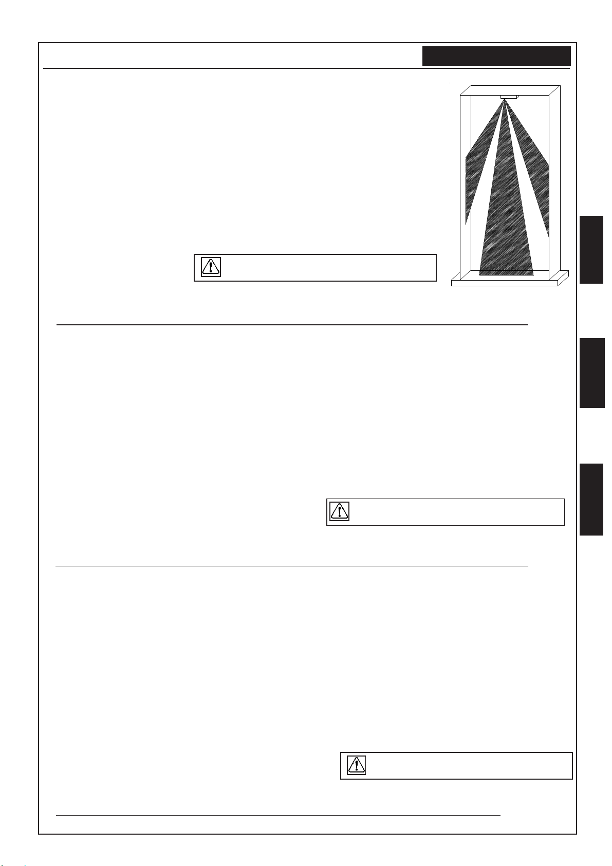
Copertura
questa funzione non garantisce comunque
che il sensore non possa essere mascherato.
Funzionamento - Working - Fonctionnement
This function does not grant anyway detector
from masking
Cette fonction ne garantit pas de toute manière
que le détecteur ne puisse pas être masqué.
WING (M) WS
I
T
A
E
N
G
F
R
A

- 6 -
[I] WIC2 WS è un trasmettitore in grado di comunicare lo stato del “Reed”.
Oltre a questo ha la possibilità di gestire un ingresso secondario “-IN” per
sensori swith-alarm con la gestione separata del numero di zona (DIP6 ON). Il
canale secondario è impostato di fabbrica aggiungendo una unità alla
numerazione del sensore impostata con i dip switch. L’acquisizione del
canale secondario avviene alla comunicazione del tamper del sensore.
Ingresso “- IN” per gestione contatti NC; è possibile la gestione dello stato dell’ingresso anche qualora si utilizzi la
funzione “doppio canale”. Il funzionamento del “Reed” è vincolato al DIP8.
Ingresso “- IN” per gestione sensori inerziali: regolare la sensibilità ruotando il trimmer RV1; Il funzionamento del
“Reed” è vincolato al DIP8.
Se impostato con funzione doppio canale, se ne tenga conto per la numerazione dei successivi
sensori.
[E] WIC2 WS is an emitter capable to communicate the status of the Reed.
Further to this , it can manage a secondary entry “IN” for “switch-alarm” sensors with separate management of zone number
(Dip 6 ON). The secondary channel is set by default adding one unit to the detector number set by dip-switch. The acquisition
of the secondary channel occurs at the communication of the detector tamper
Input “-IN” for management of NC contacts; the management of the status of the input is possible also when the “double-
channel” function is used. The working of Reed is linked to Dip 8.
Input “-IN” for management of inertial sensors; adjust sensitivity by rotating trimmer RV1. The working of Reed is linked to
Dip 8.
If set as a double-channel function, keep it in mind for numbering of following detectors.
[F] WIC2 WS est un transmetteur en mesure de communiquer l’état du «reed».
En plus de cela, il a la possibilité de gérer une entrée secondaire «- IN» pour des détecteurs switch-alarm avec la gestion
séparée du nombre de zone (DIP6 ON). Le canal secondaire est réglé en usine en ajoutant une unité à la numération du
détecteur réglé avec les dip-switch. L’acquisition du canal secondaire se fait lors de la communication du sabotage du
détecteur.
Entrée «- IN» pour la gestion de contacts NF : la gestion de l’état de l’entrée est possible alors même que la fonction «double
canal» est utilisée. Le fonctionnement du «reed» est sujet au DIP 8.
Entrée «- IN» pour la gestion des détecteurs inertiels : régler la sensibilité en tournant le trimmer RV1 ; Le fonctionnement
du «reed» est sujet au DIP 8.
Si réglé avec la fonction double canal, en tenir compte pour la numération des détecteurs suivants.
Collegamento Vibr.o SW
Connection of inertial sensor or
“swith-alarm” sensor
Connection Vibr.ou SW
)émref(-)desolc(-)osuihc(-NO )trevuo(--)nepo(-)otrepa(-FFO
1S oppartsitnaatilibasiD repmat-itnafognilbanesiD fitcaniegahcarra-itnA
oppartsitnaatilibA fitcaegahcarra-itnA repmat-itnafognilbanE
6PID elanacoippodenoitsegatilibA lennahcelbuodfotnemeganamgnilbanE lanacelbuodnoitsegalevitcA
elanacolognisenoitseG lanacnu'dnoitsegaltnemeuqinuevitcA lennahcenoylnofotnemeganamgnilbanE
7PID ossoRDELatilibA deLgnilbanE eguorDELniomételevitcA
ossorDELatilibasiD eguorDELniomételevitcaséD deLdergnilbanesiD
8PID "onretnideeR"ledenoitsegalatilibasiD "deeRedisni"fotnemeganamgnilbanesiD "enretniDEER"udnoitsegalevitcaséD
"onretnideeR"enoitsegatilibA "enretniDEER"udnoitsegalevitcA "deeRedisni"fotnemeganamgnilbanE
NI- otazzilitunoneS olifaetnopnunocosuihceresse'ved, repmujderiwahtiwdesolcebtsumti,desutonfI ésilitunoniS erialiftnopnucevaremrefel,
1VR eratnemuareP nieratour,àtilibisnesal oiraroosnes ytivitisnesesaercniotredroniesiwkcolcetatoR retnemguaruoP eriarohsnesnerenruot,étilibisnesal
+
RV1
Reed
S1
Funzionamento - Working - Fonctionnement - WIC2 WS
Dip Switch / Jumper
-IN
+
-
RV1 S1
on
1 8
Reed
Position of the magnet
Position aimant
Posizione magnete
WIC2 WS
I
T
A
E
N
G
F
R
A

- 7 -
.
erosneS srotceteD
sruetceteD
1PID 2PID 3PID 4PID 5PID erosneS srotceteD
sruetceteD
1PID 2PID 3PID 4PID 5PID
1NO NO NO NO NO 71 NO NO NO NO FFO
2FFO NO NO NO NO 81 FFO NO NO NO FFO
3NO FFO NO NO NO 91 NO FFO NO NO FFO
4FFO FFO NO NO NO 02 FFO FFO NO NO FFO
5NO NO FFO NO NO 12 NO NO FFO NO FFO
6FFO NO FFO NO NO 22 FFO NO FFO NO FFO
7NO FFO FFO NO NO 32 NO FFO FFO NO FFO
8FFO FFO FFO NO NO 42 FFO FFO FFO NO FFO
9NO NO NO FFO NO 52 NO NO NO FFO FFO
01 FFO NO NO FFO NO 62 FFO NO NO FFO FFO
11 NO FFO NO FFO NO 72 NO FFO NO FFO FFO
21 FFO FFO NO FFO NO 82 FFO FFO NO FFO FFO
31 NO NO FFO FFO NO 92 NO NO FFO FFO FFO
41 FFO NO FFO FFO NO 03 FFO NO FFO FFO FFO
51 NO FFO FFO FFO NO 13 NO FFO FFO FFO FFO
61 FFO FFO FFO FFO NO 23 FFO FFO FFO FFO FFO
:enoiznettA :noitnettA
ilibinopsidonosnon,SWsulPedrocnoCelartnecalnocitazzilaeritnaipmiilgeN .03,92,02,91,01,9enozel :elbaliavatonerasenozgniwollofehtSWsulPedrocnoChtiwsmetsysehtnI 03,92,02,91,01,9 senozsel,SWsulPedrocnoCelartnecalcevasésilaérsemètsysselsnaD .selbinopsidsaptnosen03,92,02,91,01,9
- [I] L’ acquisizione dei
sensori avviene solo per
comunicazioni Tamper.
- Ogni sensore deve
avere una codifica di
zona distinta
- [E] Any detector must
have a separate
codification. The
acquisition of the
detectors only occurs by
communicating of
Tamper.
- [F] Chaque détecteur
doit avoir une codification
de zone différente
- L’acquisition des
détecteurs se fait
uniquement par
communication sabotage.
Numerazione sensori - Numbering detectors - Numération detecteurs
Dichiarazione di conformità - Information in conformity
!ATTENZIONE!
Pericolo di esplosione se la batteria non viene sostituita in modo corretto; sostituire solo con tipo uguale o equivalente
a quella raccomandata dal costruttore.
Non aprire, non ricaricare, non esporre ad alte temperature, non esporre al fuoco.
Non disperdere nell’ambiente le batterie scariche, ma gettarle negli appositi contenitori di raccolta.
Tenere lontano dalla portata dei bambini. ! ATTENTION !
Danger of explosion if battery is not replaced in correct way; replace only with same or equivalent type recommended by manufacturer.
Do not open, do not recharge, do not expose to high temperatures, do not expose to fire. Do not leave low batteries in the environment but
dispose of them in the proper containers. Keep away from children.
INFORMAZIONI IN CONFORMITA’ CON LA DIRETTIVA 1999/5/CEE (R&TTE)
-[I] Il prodotto oggetto della presente dichiarazione è conforme alle prescrizioni fondamentali della Direttiva 1999/5/CEE (R&TTE) sugli
apparati radiotrasmittenti di debole potenza e sull’uso delle frequenze dello spettro radioelettrico, in accordo anche con la raccomanda-
zione CEPT 70-03.
- [E] The product here described is in conformity to the essential prescriptions of the Directive 1999/5/CEE (R&TTE) on
the radio-transmitting devices of low power and on the use of frequencies of the radioelectrical spectrum, in accordance
with CEPT 70-03 recommandation.
Marca - Trade mark
AVS ELECTRONICS
Modello - Model -
SPY WS - WING (M) WS - WIC2 WS
Frequenza di lavoro - Working frequency
868,350Mhz
Tipo di alimentazione - Type of supplying
Batteria al litio - Lithium battery
Tensione nominale - Nominal tension
Corrente nominale - Nominal current
20 mA (in trasmissione)
25 µA (riposo)
Paesidellacomunitàeuropeadov’èdestinato ad
-Counties of use in European Community
AUT-BEL-DNK-E-D-GRC-ICE-I-IRL-LUX-HOL-
NOR-POR-SUI-S-UK-CZ-CYP-EST-HNG-LTU-
LVA-MLT-POL-SVN-SVK-BIH-BUL-MKD-SCG-
TUR
Data - Date
01 - 12 - 2006
I
T
A
E
N
G
F
R
A

- 8 -
AA
AA
AVS ELECTRVS ELECTR
VS ELECTRVS ELECTR
VS ELECTRONICS SONICS S
ONICS SONICS S
ONICS S.p.p
.p.p
.p.A..A.
.A..A.
.A.
Via Valsugana, 63Via Valsugana, 63
Via Valsugana, 63
35010 (Padova) ITALY35010 (Padova) ITALY
35010 (Padova) ITALY
Tel. 049 9698 411 / Fax. 049 9698 407Tel. 049 9698 411 / Fax. 049 9698 407
Tel. 049 9698 411 / Fax. 049 9698 407
www.avselectronics.comwww.avselectronics.com
www.avselectronics.com
Assistenza Tecnica: 049 9698 444Assistenza Tecnica: 049 9698 444
Assistenza Tecnica: 049 9698 444
AVS ELECTRONICS S.p.a. si riserva il diritto di apportare modifiche in qualsiasi momento e senza preavviso.
AVS Electronics S.p.A. reserves the right to revise or make changes to this product at any time and without notification
AVS ELECTRONICS S.p.A. se réserve le droit d’apporter des modifications à n’importe quel moment et sans préavis.
Dichiarazione di conformità - Information in conformity
DICHIARAZIONEDICONFORMITA
(MANUFACTURERS DECLARATION OF CONFORMITY)
DICHIARA CHE LA SEGUENTE APPARECCHIATURA
(DECLARES THAT THE FOLLOWING EQUIPMENT)
RISULTA CONFORME CON QUANTO PREVISTO DALLE SEGUENTI DIRETTIVE COMUNITARIE:
(IS IN ACCORDANCE WITH THE FOLLOWING COMMUNITY DIRECTIVES)
E CHE SONO STATE APPLICATE LE SEGUENTI NORMATIVE
(APPLYING THE FOLLOWING NORMS OR STANDARDS)
IDENTIFICATORE DI CLASSE DEL DISPOSITIVO (per apparati RFregolamentati dalla direttivaR&TTE)
(Equipment class identifier (RF products falling under the scope of R&TTE))
Il costruttore dichiara sotto la propria responsabilità che questo prodotto é conforme
alla direttiva 93/68/EEC (marcatura) e soddisfa i requisiti essenziali e altre prescrizioni
rilevanti della direttiva 1999/5/EC (R&TTE) in base ai risultati dei test condotti usando le
normative (non) armonizzate in accordo con le Direttive sopracitate.
(We declare under our sole responsibility that this product is in conformity with directive 93/68/EEC
(Marking) and/or complies to the essential requirements and all other relevant provisions of the
1999/5/EC (R&TTE) based on test results using (non)harmonized standards in accordance with the
Directives mentioned)
Luogo (Place) : Curtarolo
Data (Date) : DIC 2006 Firma (Signature)
Nome (Name) : G. BARO Amministratore
(Managing Director)
erotturtsoC )rerutcafunaM( APSSCINORTCELESVA
ozziridnI )sserddA( YLATI-)DP(oloratruC01053-36,anaguslaVaiV
:arutaihccerappA’lledemoN )emaNtnempiuqE( :SW2CIW-SW)M(GNIW-SWYPS
arutaihccerappAidopiT )tnempiuqEfoepyT( :OIDARAIVEROSNES )SROTCETEDSSELERIW(
olledoM )ledoM( :
enoizurtsoCidonnA )erutcafunaMforaeY( :6002
)CME(CE/633/98 )ETT&R(CE/50/99
)DVL(CE/32/37
3-022003NE 3-984103NE 4-03105NE 05906NE
elbacilppAtoN )tcudorp1ssalc(enoN X)tcudorp2ssalc(
I
T
A
E
N
G
F
R
A
This manual suits for next models
2
Table of contents
Other AVS Electronics Accessories manuals

AVS Electronics
AVS Electronics OUTSPIDER PA User manual

AVS Electronics
AVS Electronics SPECTRUM DT AM User manual

AVS Electronics
AVS Electronics JET DT WS 4 User manual

AVS Electronics
AVS Electronics SPECTRUM PA WS WALL STD User manual

AVS Electronics
AVS Electronics SPECTRUM DT WS AM User manual

AVS Electronics
AVS Electronics WIC 3 WS User manual

AVS Electronics
AVS Electronics SPIDER PA User manual

AVS Electronics
AVS Electronics TS85 V LED HP Specification sheet

AVS Electronics
AVS Electronics WIC 4 User manual

AVS Electronics
AVS Electronics JET DT WS 4 User manual