Detcon MicroSafe DM-634C User manual

Detcon MicroSafe™
Model DM-634C
Oxygen Deficiency Sensor (0-25% O2)
Operator’s Installation and Instruction Manual
DETCON, Inc.
4055 Technology Forest Blvd, Suite 100,
The Woodlands, Texas 77381
Ph.281.367.4100 / Fax 281.298.2868
www.detcon.com
August 03, 2018 • Document #2016 • Revision .066

DM-634C Oxygen Sensor Assembly
DM-634C O2 Sensor Instruction Manual ii
This page left intentionally blank

DM-634C Oxygen Sensor Assembly
DM-634C O2 Sensor Instruction Manual iii
Table of Contents
3.0 Description................................................................................................................................................. 1
3.0.1 Sensor Technology....................................................................................................................... 1
3.0.2 Microprocessor Control Circuit.................................................................................................... 2
3.0.3 Base Connector Board.................................................................................................................. 2
3.0.4 Explosion Proof Enclosure........................................................................................................... 3
3.1 Principle of Operation .......................................................................................................................... 3
3.2 Application........................................................................................................................................... 4
3.2.1 Sensor Placement/Mounting......................................................................................................... 4
3.2.2 Interference Data.......................................................................................................................... 4
3.3 Specifications ....................................................................................................................................... 4
3.4 Operating Software............................................................................................................................... 5
3.4.1 Normal Operation......................................................................................................................... 5
3.4.2 Calibration Mode.......................................................................................................................... 5
3.4.3 Program Mode.............................................................................................................................. 5
3.4.4 Program Status ............................................................................................................................. 5
3.4.5 Alarm 1 Level Adjustment........................................................................................................... 6
3.4.6 Alarm 2 Level Adjustment........................................................................................................... 6
3.4.7 Calibration Level Adjustment ...................................................................................................... 6
3.5 Installation............................................................................................................................................ 6
3.5.1 Field Wiring Table (4-20 mA output).......................................................................................... 6
3.5.2 Sensor Location............................................................................................................................ 7
3.5.3 Local Electrical Codes.................................................................................................................. 7
3.5.4 Accessibility................................................................................................................................. 8
3.5.5 Installation Procedure................................................................................................................... 8
3.6 Start Up .............................................................................................................................................. 13
3.7 Calibration.......................................................................................................................................... 13
3.7.1 Calibration Procedure - Span...................................................................................................... 14
3.7.2 Additional Notes......................................................................................................................... 15
3.7.3 Calibration Frequency................................................................................................................ 16
3.8 Status of Programming, Alarms, Calibration Level, RS-485 ID, and Sensor Life............................. 16
3.9 Programming Alarms......................................................................................................................... 17
3.9.1 Alarm Levels.............................................................................................................................. 17
3.9.2 Alarm Reset................................................................................................................................ 17
3.9.3 Other Alarm Functions............................................................................................................... 17
3.10 Program Features................................................................................................................................ 18
3.11 RS-485 Protocol................................................................................................................................. 18
3.12 Display Contrast Adjust ..................................................................................................................... 20
3.13 Trouble Shooting................................................................................................................................ 21
3.14 Spare Parts List................................................................................................................................... 22
3.15 Warranty............................................................................................................................................. 23
3.16 Service Policy..................................................................................................................................... 23
3.17 Software Flowchart ............................................................................................................................ 24
3.18 Revision Log ...................................................................................................................................... 25

DM-634C Oxygen Sensor Assembly
DM-634C O2 Sensor Instruction Manual iv
Table of Figures
Figure 1 Construction of Galvanic Cell............................................................................................................. 1
Figure 2 Microprocessor Control Circuit.......................................................................................................... 2
Figure 3 Base connector board.......................................................................................................................... 2
Figure 4 Explosion proof enclosures................................................................................................................. 3
Figure 5 Functional Block Diagram.................................................................................................................. 3
Figure 6 Typical Installation ............................................................................................................................. 8
Figure 7 Typical Outline and Mounting Dimensions........................................................................................9
Figure 8 Sensor Connector PCB ....................................................................................................................... 10
Figure 9 Control Circuit.................................................................................................................................... 11
Figure 10 Control Circuit.................................................................................................................................. 11
Figure 11 Magnetic Programming Tool............................................................................................................ 14
Figure 12 Programming Locations.................................................................................................................... 15
Figure 13 Spare parts diagram........................................................................................................................... 22
Figure 14 Software Flowchart........................................................................................................................... 24
List of Tables
Table 1 Interference Data.................................................................................................................................. 4
Table 2 Field wiring Table................................................................................................................................ 6
Shipping Address: 4055 technology Forest Blvd, Suite 100., The Woodlands Texas 77381
Mailing Address: P.O. Box 8067, The Woodlands Texas 77387-8067

DM-634C Oxygen Sensor Assembly
DM-634C O2 Sensor Instruction Manual Rev. .066 Page 1 of 25
3.0 Description
Detcon MicroSafe™ Model DM-634, oxygen deficiency sensors are non-intrusive “Smart” sensors designed
to detect and monitor O2 in air over the range of 0-25%. One of the primary features of the sensor is its
method of automatic calibration which guides the user through each step via instructions displayed on the
backlit LCD. The sensor features field adjustable, fully programmable alarms and provides relays for two
alarms plus fault as standard. The sensor come with two different outputs: analog 4-20 mA, and serial RS-
485. These outputs allow for greater flexibility in the system integration and installation. The microprocessor-
supervised electronics are packaged as a plug-in module that mates to a standard connector board. Both are
housed in an explosion proof condulet that includes a glass lens window which allows for the display of the
sensor readings as well as access to the sensor’s menu driven features via a hand-held programming magnet.
3.0.1 Sensor Technology
The sensor technology is of the two electrode, galvanic metal air battery type cell, which is housed as a field
replaceable plug–in module. The cell is diffusion limited and functions as a direct current generator
proportional to the amount of oxygen adsorption. The sensors are temperature compensated and show good
accuracy and stability over the operating temperature range -4° to +122° Fahrenheit. The sensor is warranted
for two year and has an expected service life of up to two years in ambient air at 20.9% oxygen.
Figure 1 Construction of Galvanic Cell

DM-634C Oxygen Sensor Assembly
DM-634C O2 Sensor Instruction Manual Rev. .066 Page 2 of 25
3.0.2 Microprocessor Control Circuit
The control circuit is microprocessor based and is packaged as a plug-in field replaceable module, facilitating
easy replacement and minimum down time. Circuit functions include a basic sensor pre-amplifier, on-board
power supplies, microprocessor, back lit alpha numeric display, alarm status LED indicators, magnetic
programming switches, an RS-485 communication port, and a linear 4-20 mA DC output.
Figure 2 Microprocessor Control Circuit
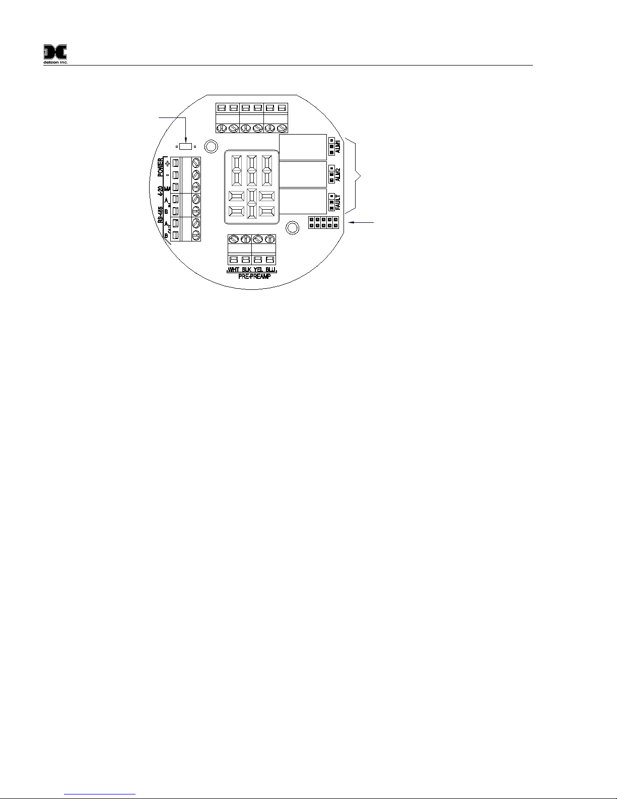
3.0.3 Base Connector Board
The base connector board is mounted in the explosion proof enclosure and includes: the mating connector for
the control circuit, reverse input and secondary transient suppression, input filter, alarm relays, lugless
terminals for all field wiring, and a terminal strip for storing unused programming jumper tabs. The alarm
relays are contact rated 5 amps @ 250 VAC, 5 amps @ 30 VDC and coil rated at 24 VDC. Gold plated
program jumpers are used to select either the normally open or normally closed relay contacts.
Customer
Wiring
Wiring to
O2 Sensor
Figure 3 Base connector board

DM-634C Oxygen Sensor Assembly
DM-634C O2 Sensor Instruction Manual Rev. .066 Page 3 of 25
3.0.4 Explosion Proof Enclosure
The sensors are packaged in a cast metal explosion proof enclosure. The enclosure is fitted with a threaded
cover that has a glass lens window. Magnetic program switches located behind the transmitter module face
plate are activated through the lens window via a hand-held magnetic programming tool allowing non-
intrusive operator interface with the sensor. All calibration and alarm level adjustments can be accomplished
without removing the cover or declassifying the area. Electrical classification is
Class I; Groups B, C, D; Div. 1.
Figure 4 Explosion proof enclosures
3.1 Principle of Operation
Method of detection is by a controlled rate of diffusion. Air and gas diffuse through a sintered stainless steel
filter and a diffusion barrier. As oxygen is adsorbed into the electrolyte solution a current is generated between
the cathode and anode electrodes. This current output rises with increases in oxygen concentration and reverses
with lower concentrations. The quick response of the cell results in continuous monitoring of ambient air
conditions.
Figure 5 Functional Block Diagram
n

DM-634C Oxygen Sensor Assembly
DM-634C O2 Sensor Instruction Manual Rev. .066 Page 4 of 25
3.2 Application
Model DM-634 MicroSafe™ sensors are designed to detect and monitor oxygen deficiency in ambient air in
the range of 0-25%. Minimum sensitivity and scale resolution is 0.1%. Operating temperature range is -4° F.
to +122° F. While the sensor is capable of operating outside these temperatures, performance specifications
are verified within the limit.
3.2.1 Sensor Placement/Mounting
Sensor location should be reviewed by facility engineering and safety personnel. Area leak sources and
perimeter mounting are typically used to determine number and location of sensors. The sensors are generally
located 2 - 4 feet above grade.
3.2.2 Interference Data Table 1 Interference Data
Methane
100% = 0
Hydrocarbons
100% = 0
Hydrogen
100% = < 2%
Carbon Monoxide
20% = < 0.5%
3.3 Specifications
Method of Detection Air battery diffusion/adsorption
Electrical Classification Class I; Groups B, C, D; Div. 1.
Response Time (T90) T90 < 20 seconds
Clearing Time 90% < 20 seconds
Repeatability ± 2% FS
Range 0-25% O2
Operating Temperature -4° to +122° F
Accuracy ± 2% FS
Sensor Warranty 2 year conditional
Power Consumption Normal Operation = 28mA (<3/4 watt); Full Alarm = 85mA (2 watt)
Output 3 relays (alarm 1, alarm 2, and fault) contact rated 5 amps @ 250VAC
5 amps @ 30VDC; Linear 4-20mA DC; RS-485 Modbus™
Input Voltage 22.5-28 VDC

DM-634C Oxygen Sensor Assembly
DM-634C O2 Sensor Instruction Manual Rev. .066 Page 5 of 25
3.4 Operating Software
Operating software is menu listed with operator interface via the two magnetic program switches located under
the face plate. The two switches are referred to as “PGM 1” and “PGM 2”. The menu list consists of 3 items
which include sub-menus as indicated below. (Note: see Figure 14 at the end of the manual for a complete
software flowchart.)
1. Normal Operation
a) Current Status
2. Calibration Mode
a) Span
3. Program Menu
a) Program Status
b) Alarm 1 Level
c) Alarm 2 Level
d) Set Calibration Level
3.4.1 Normal Operation
In normal operation, the display tracks the current status of the sensor and gas concentration and appears as:
“20.9 % O2”" The mA current output corresponds to the monitoring level of 0-25% O2 = 4-20 mA.
3.4.2 Calibration Mode
Calibration mode allows for sensor zero and span adjustments. “2 - SPAN”
The default span adjustment is set at 20.9% which is the normal atmospheric concentration of O2. Span gas
concentrations other than 20.9 % may be used. Refer to section 3.4.7 for details. “AUTO SPAN”
3.4.3 Program Mode
The program mode provides a program status menu and allows for the adjustment of alarm set point levels and
the programming of the calibration gas level setting.
The program mode provides a program status menu (View Program Status) to check operational parameters
and allows for the selection of the calibration gas level setting.
3.4.4 Program Status
The program status scrolls through a menu that displays:
*The gas type, range of detection and software version number. The menu item appears as: “O2 0-25 V528J”
*The alarm set point level of alarm 1. The menu item appears as: “ALM1 SET @ xx.x%”
*The alarm firing direction of alarm 1. The menu item appears as: “ALM1 DESCENDING” or ascending.
*The alarm relay latch mode of alarm 1. The menu item appears as: “ALM1 NONLATCHING” or latching.
*The alarm relay energize state of alarm 1. The menu item appears as: “ALM1 DE-ENERGIZED” or
energized.
*The alarm set point level of alarm 2. The menu item appears as: “ALM2 SET @ xx.x%”
*The alarm firing direction of alarm 2. The menu item appears as: “ALM2 DESCENDING” or ascending.
*The alarm relay latch mode of alarm 2. The menu item appears as: “ALM2 LATCHING” or nonlatching.
*The alarm relay energize state of alarm 2. The menu item appears as: “ALM2 DE-ENERGIZED” or
energized.

DM-634C Oxygen Sensor Assembly
DM-634C O2 Sensor Instruction Manual Rev. .066 Page 6 of 25
*The alarm relay latch mode of the fault alarm. The menu item appears as: “FLT NONLATCHING” or
latching.
*The alarm relay energize state of the fault alarm. The menu item appears as
:
“FLTENERGIZED”
or
de-energized.
*The calibration gas level setting. The menu item appears as: “CalLevel @ xx.x%”
*Identification of the RS-485 ID number setting. The menu item appears as: “485 ID SET @ ##”
*The estimated remaining sensor life. The menu item appears as: “SENSOR LIFE 100%”
3.4.5 Alarm 1 Level Adjustment
The alarm 1 level is adjustable from 2.5% to 22.5%. The menu item appears as: “SET ALM1 @ 19.5%”
3.4.6 Alarm 2 Level Adjustment
The alarm 2 level is adjustable from 2.5% to 22.5%. The menu item appears as: “SET ALM2 @ 17.5%”
3.4.7 Calibration Level Adjustment
The calibration level is adjustable from 15.0% to 25.0% O2. The menu item appears as: “CalLevel @ xx.x%”
3.5 Installation
Optimum performance of ambient air/gas sensor devices is directly relative to proper location and installation
practice.
3.5.1 Field Wiring Table (4-20 mA output)
Detcon MicroSafe™ O2 sensor assemblies require three conductor connection between power supplies and
host electronic controllers. Wiring designators are + (DC), – (DC), and mA (sensor signal). Maximum single
conductor resistance between sensor and controller is 10 ohms. Maximum wire size for termination in the
sensor assembly terminal board is 14 gauge
Table 2 Field wiring Table
Note 1: This wiring table is based on stranded tinned copper wire and is designed to serve
as a reference only.
Note 2: Shielded cable may be required in installations where cable trays or conduit runs
include high voltage lines or other sources of induced interference.
The RS-485 (if applicable) requires 24 gauge, two conductor, shielded, twisted pair cable between sensor and
host PC. Use Belden part number 9841. Two sets of terminals are located on the connector board to facilitate
serial loop wiring from sensor to sensor. Wiring designators are A & B (IN) and A & B (OUT).
AWG
Meters
Feet
20
240
800
18
360
1200
16
600
2000
14
900
3000

DM-634C Oxygen Sensor Assembly
DM-634C O2 Sensor Instruction Manual Rev. .066 Page 7 of 25
3.5.2 Sensor Location
Selection of sensor location is critical to the overall safe performance of the product. Five factors play an
important role in selection of sensor locations:
(1) Density of the gas to be detected
(2) Most probable leak sources within the industrial process
(3) Ventilation or prevailing wind conditions
(4) Personnel exposure
(5) Accessibility for routine maintenance
Density - Placement of sensors relative to the density of the target gas is such that sensors for the detection of
heavier than air gases should be located within 2-4 feet of grade as these heavy gases will tend to settle in low
lying areas. For gases lighter than air, sensor placement should be 4-8 feet above grade in open areas or in
pitched areas of enclosed spaces.
Leak Sources - Most probable leak sources within an industrial process include flanges, valves, and tubing
connections of the sealed type where seals may either fail or wear. Other leak sources are best determined by
facility engineers with experience in similar processes.
Ventilation - Normal ventilation or prevailing wind conditions can dictate efficient location of gas sensors in a
manner where the migration of gas clouds is quickly detected.
Personnel Exposure - The undetected migration of gas clouds should not be allowed to approach
concentrated personnel areas such as control rooms, maintenance or warehouse buildings. A more general and
applicable thought toward selecting sensor location is combining leak source and perimeter protection in the
best possible configuration.
Note: For products utilizing the aluminum junction box option, the conduit seal shall be
placed at the entry to the junction box (see Figure 6 as an example). For products utilizing
the stainless steel junction box option, the conduit seal shall be placed within 18” of the
enclosure. Crouse Hinds type EYS2, EYD2 or equivalent are suitable for this purpose.
3.5.3 Local Electrical Codes
Consideration should be given to easy access by maintenance personnel as well as the
consequences of close proximity to contaminants that may foul the sensor prematurely.

DM-634C Oxygen Sensor Assembly
DM-634C O2 Sensor Instruction Manual Rev. .066 Page 8 of 25
3.5.4 Accessibility
Consideration should be given to easy access by maintenance personnel as well as the consequences of close
proximity to contaminants that may foul the sensor prematurely.
Drain
Conduit
"T" EYS Seal Fitting
PGM 1
PGM 2
MODEL DM-534C
HOUSTON, TEXAS
FLT CAL
MicroSafe O2 Gas Sensor
ALM ALM
TM
Figure 6 Typical Installation
NOTE: For products utilizing the aluminum junction box option, the conduit seal shall be
placed at the entry to the junction box (see Figure 6 as an example). For products utilizing
the stainless steel junction box option, the conduit seal shall be placed within 18” of the
enclosure. Crouse Hinds type EYS2, EYD2 or equivalent are suitable for this purpose.
3.5.5 Installation Procedure
a)
Remove the junction box cover and un-plug the control circuit by grasping the two thumb
screws and pulling outward.
b)
Securely mount the sensor junction box in accordance with recommended practice. See
dimensional drawing (Figure 7).
c)
Observing correct polarity, terminate 3 conductor field wiring, RS-485 wiring, and applicable
alarm wiring to the sensor base connector board in accordance with the detail shown in Figure
3. Normally open and normally closed Form C dry contacts (rated 5 amp @ 120VAC; 5 amp
@ 30VDC) are provided for Fault, Alarm 1, and Alarm 2.
d)
Position gold plated jumper tabs located on the connector board in accordance with desired
Form C dry con- tact outputs: NO = Normally Open; NC = Normally closed (see Figure 8).

DM-634C Oxygen Sensor Assembly
DM-634C O2 Sensor Instruction Manual Rev. .066 Page 9 of 25
NOTE:If a voltage signal output is desired in place of the 4-20mA output, a 1/4 watt
resistor must be installed in position R1 of the terminal board. A 250Ωresistor will
provide a 1-5V output (– to mA). A 100Ωresistor will provide a .4-2V output, etc. This
linear signal corresponds to 0-100% of scale (see Figure 8).
e)
Pro
gram the alarms via the gold plated jumper tab positions located on the CPU board (see
Figure 9). Alarm 1 and Alarm 2 have three jumper programmable functions: latching/non-
latching relays, normally energized/normally de-energized relays, and ascending/descending
alarm set points.
The fault alarm has two jumper programmable functions: latching/non-latching relay, and normally
energized/normally de-energized relay. The default settings of the alarms (jumpers removed) are normally de-
energized relays, non-latching relays, and alarm points that activate during descending gas conditions.
5.5"
6.1"
5.825"
7.92"
2"
0.5"
4.65"
Wall (or other
mounting surface
Splash Guard
O2 Sensor
Cal Port
1/4" Mounting holes
8-32 tapped
ground point
3/4" NPT Ports
Figure 7 Typical Outline and Mounting Dimensions
DM-634C Oxygen Sensor Assembly
DM-634C O2 Sensor Instruction Manual Rev. .066 Page 10 of 25
VDC Power In
4-20mA Output
RS-485 In
RS-485 Out
TO SENSOR
Place un-used alarm
programming
jumper tabs here
Alarm Dry Contacts
Fault ALM2 ALM1
Jumper Programmable Alarm Outputs
Normally Open or Normally Closed
Optional Voltage
Developing Resistor
Use 250ohm 1/4W R1
Fault
ALM2
ALM1
Figure 8 Sensor Connector PCB
If a jumper tab is installed in the latch position, that alarm relay will be in the latching mode. The latching
mode will latch the alarm after alarm conditions have cleared until the alarm reset function is activated. The
non-latching mode (jumper removed) will allow alarms to de-activate automatically once alarm conditions
have cleared. If a jumper tab is installed in the energize position, that alarm relay will be in the energized
mode. The energized mode will energize or activate the alarm relay when there is no alarm condition and de-
energize or de-activate the alarm relay when there is an alarm condition. The de-energized mode (jumper
removed) will energize or activate the alarm relay during an alarm condition and de-energize or de-activate the
alarm relay when there is no alarm condition.
If a jumper tab is installed in the ascending position, that alarm relay will be in the ascending mode. The
ascending mode will cause an alarm to fire when the gas concentration detected is greater than or equal to the
alarm set point. The descending mode (jumper removed) will cause an alarm to fire when the gas concentration
detected is lesser than or equal to the alarm set point. Except in special applications, O2 gas monitoring will
require alarms to fire in “DESCENDING” gas conditions.
Any unused jumper tabs should be stored on the connector board on the terminal strip labeled “Unused
Jumpers” (see Figure 8).

DM-634C Oxygen Sensor Assembly
DM-634C O2 Sensor Instruction Manual Rev. .066 Page 11 of 25
FAULT
ALARM1
ALA
RM2
Latch
Energize
Latch
Ascending
Energize
Ascending
Energize
CPU Board - Top View
Alarm Programming Jumpers
CPU Board
Figure 9 Control Circuit
f)
If applicable, set the RS-485 ID number via the two rotary dip switches located on the pre-amp board
(see Figure 10). There are 256 different ID numbers available which are based on the hexadecimal
numbering system. If RS-485 communications are used, each sensor must have its own unique ID
number. Use a jeweler’s screwdriver to set the rotary dip switches according to the table listed on the
following page. If RS-485 communications are not used, leave the dip switches in the default position
which is zero/zero (0)-(0)
Preamp Board
9
1
2
3
4
5
6
7
8
0
9
1
2
3
4
5
6
7
8
0
Preamp Board - Side View
RS-485 ID Set Dip Switches
SW1 SW2
Figure 10 Control Circuit

DM-634C Oxygen Sensor Assembly
DM-634C O2 Sensor Instruction Manual Rev. .066 Page 12 of 25
ID#
SW1
SW2
ID#
SW1
SW2
ID#
SW1
SW2
ID#
SW1
SW2
ID#
SW1
SW2
ID#
SW1
SW2
none
0
0
43
2
B
86
5
6
129
8
1
172
A
C
215
D
7
1
0
1
44
2
C
87
5
7
130
8
2
173
A
D
216
D
8
2
0
2
45
2
D
88
5
8
131
8
3
174
A
E
217
D
9
3
0
3
46
2
E
89
5
9
132
8
4
175
A
F
218
D
A
4
0
4
47
2
F
90
5
A
133
8
5
176
B
0
219
D
B
5
0
5
48
3
0
91
5
B
134
8
6
177
B
1
220
D
C
6
0
6
49
3
1
92
5
C
135
8
7
178
B
2
221
D
D
7
0
7
50
3
2
93
5
D
136
8
8
179
B
3
222
D
E
8
0
8
51
3
3
94
5
E
137
8
9
180
B
4
223
E
F
9
0
9
52
3
4
95
5
F
138
8
A
181
B
5
224
E
0
10
0
A
53
3
5
96
6
0
139
8
B
182
B
6
225
E
1
11
0
B
54
3
6
97
6
1
140
8
C
183
B
7
226
E
2
12
0
C
55
3
7
98
6
2
141
8
D
184
B
8
227
E
3
13
0
D
56
3
8
99
6
3
142
8
E
185
B
9
228
E
4
14
0
E
57
3
9
100
6
4
143
8
F
186
B
A
229
E
5
15
0
F
58
3
A
101
6
5
144
9
0
187
B
B
230
E
6
16
1
0
59
3
B
102
6
6
145
9
1
188
B
C
231
E
7
17
1
1
60
3
C
103
6
7
146
9
2
189
B
D
232
E
8
18
1
2
61
3
D
104
6
8
147
9
3
190
B
E
233
E
9
19
1
3
62
3
E
105
6
9
148
9
4
191
B
F
234
E
A
20
1
4
63
3
F
106
6
A
149
9
5
192
C
0
235
E
B
21
1
5
64
4
0
107
6
B
150
9
6
193
C
1
236
E
C
22
1
6
65
4
1
108
6
C
151
9
7
194
C
2
237
E
D
23
1
7
66
4
2
109
6
D
152
9
8
195
C
3
238
E
E
24
1
8
67
4
3
110
6
E
153
9
9
196
C
4
239
F
F
25
1
9
68
4
4
111
6
F
154
9
A
197
C
5
240
F
0
26
1
A
69
4
5
112
7
0
155
9
B
198
C
6
241
F
1
27
1
B
70
4
6
113
7
1
156
9
C
199
C
7
242
F
2
28
1
C
71
4
7
114
7
2
157
9
D
200
C
8
243
F
3
29
1
D
72
4
8
115
7
3
158
9
E
201
C
9
244
F
4
30
1
E
73
4
9
116
7
4
159
9
F
202
C
A
245
F
5
31
1
F
74
4
A
117
7
5
160
A
0
203
C
B
246
F
6
32
2
0
75
4
B
118
7
6
161
A
1
204
C
C
247
F
7
33
2
1
76
4
C
119
7
7
162
A
2
205
C
D
248
F
8
34
2
2
77
4
D
120
7
8
163
A
3
206
C
E
249
F
9
35
2
3
78
4
E
121
7
9
164
A
4
207
C
F
250
F
A
36
2
4
79
4
F
122
7
A
165
A
5
208
D
0
251
F
B
37
2
5
80
5
0
123
7
B
166
A
6
209
D
1
252
F
C
38
2
6
81
5
1
124
7
C
167
A
7
210
D
2
253
F
D
39
2
7
82
5
2
125
7
D
168
A
8
211
D
3
254
F
E
40
2
8
83
5
3
126
7
E
169
A
9
212
D
4
255
F
F
41
2
9
84
5
4
127
7
F
170
A
A
213
D
5
42
2
A
85
5
5
128
8
0
171
A
B
214
D
6
g)
Replace the plug-in control circuit and replace the junction box cover.

DM-634C Oxygen Sensor Assembly
DM-634C O2 Sensor Instruction Manual Rev. .066 Page 13 of 25
3.6 Start Up
Upon completion of all mechanical mounting and termination of all field wiring, apply system power and
observe the following normal conditions:
a) “Fault” LED is off.
b) A temporary upscale reading may occur as the sensor powers up. This upscale reading will clear to
about 20.9% within a few minutes of turn-on, assuming there is no oxygen deficient condition in the
area of the sensor.
Note:All alarms will be disabled for 1 minute after power up. In the event of power failure, the
alarm disable period will begin again once power has been restored.
Initial Operational Tests
After a warm up period has been allowed for, the sensor should be checked to verify reliable sensitivity
to O2 gas.
Material Requirements
*
Detcon P/N 6132 Threaded Calibration Adapter
*
Test gas containing 100% nitrogen at a controlled flow rate of 500 ml/min.
a) Attach the calibration adapter to the threaded sensor housing. Apply the test gas at a controlled flow
rate of 500 ml/m. Observe that the LCD display decreases to a level of 3% or less.
b) Remove the test gas and observe that the LCD display increases back to 20.9% ±2% of scale (0.5%
O2).
c) If alarms are activated during the test, and have been programmed for latching operation, reset them
according to the instructions in section 3.9.2.
Initial operational tests are complete. Detcon O2 gas sensors are pre-calibrated prior to shipment and will, in
most cases, not require significant adjustment on start up. However, it is recommended that a complete
calibration test and adjustment be performed within 24 hours of installation. Refer to calibration instructions in
later text.
3.7 Calibration
Material Requirements
* Detcon PN 327-000000-000 MicroSafe™ Programming Magnet
* Detcon PN 613-120000-000 Threaded Calibration Adapter
* Test gas containing 100% nitrogen at a controlled flow rate of 500ml/min.
Programming Magnet Operating Instructions
Operator interface to MicroSafe™ gas detection products is via magnetic switches located behind the
transmitter face plate. DO NOT remove the glass lens cover to calibrate or change programming parameters.
Two switches labeled “PGM 1” and “PGM 2” allow for complete calibration and alarm level programming
without removing the enclosure cover, thereby eliminating the need for area de-classification or the use of hot
permits. A magnetic programming tool (see Figure 11) is used to operate the switches. Switch action is defined
as momentary contact, 3 second hold, and 30 second hold. In momentary contact use, the programming magnet
is waved over a switch location. In 3 second hold, the programming magnet is held in place over a switch
location for 3 or more seconds. In 30 second hold, the programming magnet is held in place over a switch
location for 30 or more seconds. Three and thirty second hold is used to enter or exit calibration and program
menus while momentary contact is used to make adjustments. The location of “PGM 1” and “PGM 2” are
shown in Figure 12.

DM-634C Oxygen Sensor Assembly
DM-634C O2 Sensor Instruction Manual Rev. .066 Page 14 of 25
NOTE: If, after entering the calibration or program menus, there is no interaction with the
menu items for more than 30 seconds, the sensor will return to its normal operating
condition.
Figure 11 Magnetic Programming Tool
3.7.1 Calibration Procedure - Span
NOTE 1: Before performing an ambient air O
2
span calibration, be sure there is no
oxygen deficient condition present.
CAUTION: Verification of the correct calibration gas level setting and calibration span
gas concentration is required before “span” calibration. These two numbers must be equal.
Calibration consists of entering the calibration function and following the menu-displayed instructions. The
display will ask for the application of span gas in a specific concentration. This concentration must be equal to
the calibration gas level setting. The factory default setting for span gas concentration is 20.9% O2 which is
the normal atmospheric concentration. Other concentrations may be used as long as they fall within 15.0% to
25.0% O2. However, any alternate span gas concentration value must be programmed via the calibration gas
level menu before proceeding with span calibration. Follow the instructions below for span calibration.
a) Verify the current calibration gas level setting as indicated by the programming status menu. To do
this, follow the instructions in section 3.8 and make note of the setting found in listing number 12.
The item appears as “CalGas @ xx.x %”.
b) If the calibration gas level setting is equal to your calibration span gas concentration, proceed to item
“f”. If not, adjust the calibration gas level setting so that it is equal to your calibration span gas
concentration, as instructed in items “c” through “e”.
c) Enter the programming menu by holding the programming magnet stationary over “PGM 2” for 30
seconds until the display reads “VIEW PROG STATUS”, and then withdraw the magnet. At this
point you can scroll through the programming menu by momentarily waving the programming
magnet over “PGM 1” or “PGM 2”. The menu options are: View Program Status, and Set Cal Level.

DM-634C Oxygen Sensor Assembly
DM-634C O2 Sensor Instruction Manual Rev. .066 Page 15 of 25
Figure 12 Programming Locations
d) From the programming menu scroll to the calibration level listing. The menu item appears as: “SET
CAL LEVEL”. Enter the menu by holding the programming magnet stationary over “PGM 1” for 3
seconds until the display reads “CalGas @ ## %”, then withdraw the magnet. Use the programming
magnet to make an adjustment to “PGM 1” to increase or “PGM 2” to decrease the display reading
until the reading is equal to the desired calibration span gas concentration. Exit to the programming
menu by holding the programming magnet over “PGM1” for 3 seconds.
e) Exit back to normal operation by holding the programming magnet over “PGM 2” for 3 seconds, or
automatically return to normal operation in 30 seconds.
f) From the calibration menu “2-SPAN” proceed into the span adjust function by holding the
programming magnet stationary over “PGM 2” for 3 seconds then withdraw the programming
magnet. If no change of Span level is desired, wait 30 seconds for menu to return to normal operation.
At this point the display will ask for the application of the target gas and concentration. The display
reads “APPLY xx.x %” The xx.x here will indicate the actual concentration requested.
g) Apply the calibration test gas at a flow rate of 500 milliliters per minute. If the calibration gas level is
set at 20.9% and ambient air is verified to be 20.9% (normal atmospheric concentration of O2) then
do nothing at this point. The sensor will auto calibrate to ambient air O2 concentration. After 3
minutes the sensor will auto span to the correct reading and the display will change to “REMOVE
GAS” then the display will return to the normal operating mode.
NOTE 1: If the circuitry is unable to adjust the span to the proper setting the sensor will
enter into the calibration fault mode which will cause the display to alternate between the
sensor’s current status reading and the calibration fault screen which appears as: “CAL
FAULT” (see section 3.7.3).
3.7.2 Additional Notes
1. Upon entering the calibration menu, the 4-20 mA signal drops to 2 mA and is held at this level until
you return to normal operation.
2. If during calibration the sensor circuitry is unable to attain the proper adjustment for span, the sensor
will enter into the calibration fault mode and cause the display to alternate between the sensor’s
current status reading and the calibration fault screen which appears as: “CAL FAULT” If this occurs
you may attempt to recalibrate by entering the calibration menu as described in section 3.7.1a. If the
sensor fails again, defer to technical trouble shooting.

DM-634C Oxygen Sensor Assembly
DM-634C O2 Sensor Instruction Manual Rev. .066 Page 16 of 25
3.7.3 Calibration Frequency
In most applications, monthly to quarterly calibration intervals will assure reliable detection. However,
industrial environments differ. Upon initial installation and commissioning, close frequency tests should be
performed, weekly to monthly. Test results should be recorded and reviewed to determine a suitable
calibration interval.
3.8 Status of Programming, Alarms, Calibration Level, RS-485 ID, and
Sensor Life
The programming menu has a programming status listing that allows the operator to view the gas, range, and
soft- ware version number of the program, as well as the current alarm settings, calibration gas level setting,
RS-485 ID number, and estimated remaining sensor life. The programming menu also allows the changing
of alarm levels (see section 3.9) and the programming of the calibration gas level setting (see section 3.7.2).
The following procedure is used to view the programming status of the sensor:
a) First, enter the programming menu by holding the programming magnet stationary over “PGM 2” for
30 seconds until the display reads “VIEW PROG STATUS”, then withdraw the magnet. At this point
you can scroll through the programming menu by momentarily waving the programming magnet over
“PGM 1” or “PGM 2”. The menu options are: View Program Status, Set Alarm 1 Level, Set Alarm 2
Level, and Set Cal Level.
b) Next, scroll to the “VIEW PROG STATUS” listing and then hold the programming magnet over
“PGM 1” for 3 seconds. The menu will then automatically scroll, at five second intervals, through the
following information before returning back to the “VIEW PROG STATUS” listing.
1. The gas type, range of detection and software version number. The menu item appears as:
“O2 0-25 V528J”
2. The alarm set point level of alarm 1. The menu item appears as: “ALM1 SET @ 19.5%”
3. The alarm firing direction of alarm 1. The menu item appears as: “ALM1 DESCENDING”
4. The alarm relay latch mode of alarm 1. The menu item appears as:
“ALM1 NONLATCHING”
5. The alarm relay energize state of alarm 1. The menu item appears as:
“ALM1 DE-ENERGIZED”
6. The alarm set point level of alarm 2. The menu item appears as: “ALM2 SET @ 17.5%”
7. The alarm firing direction of alarm 2. The menu item appears as: “ALM2 DESCENDING”
8.
The alarm relay latch mode of alarm 2. The menu item appears as: “ALM2 LATCHING”
9. The alarm relay energize state of alarm 2. The menu item appears as:
“ALM2 DE-ENERGIZED”
10. The alarm relay latch mode of the fault alarm. The menu item appears as:
“FLT NONLATCHING”
11. B The alarm relay energize state of the fault alarm. The menu item appears as:
“FLT ENERGIZED”
12. Calibration gas level setting. The menu appears as “CalLevel @ xx.x%”
13. Identification of the RS-485 ID number setting. The menu item appears as:
“485 ID SET @ 1”
14. The estimated remaining sensor life. The menu item appears as: “SENSOR LIFE 100%”
c) Exit back to normal operations by holding the programming magnet over “PGM 2” for 3 seconds, or
automatically return to normal operation in 30 seconds.
Table of contents
Other Detcon Measuring Instrument manuals


Popular Measuring Instrument manuals by other brands

Keithley
Keithley 660A instruction manual

PCB Piezotronics
PCB Piezotronics INI SENSORS 683A100001 Installation and operating manual

Control Company
Control Company TRACEABLE 4080 instructions

Magnetrol
Magnetrol Echotel 335 Installation and operating manual

Siemens
Siemens DESIGO PX -U Series manual

Ametek
Ametek iPac user guide


