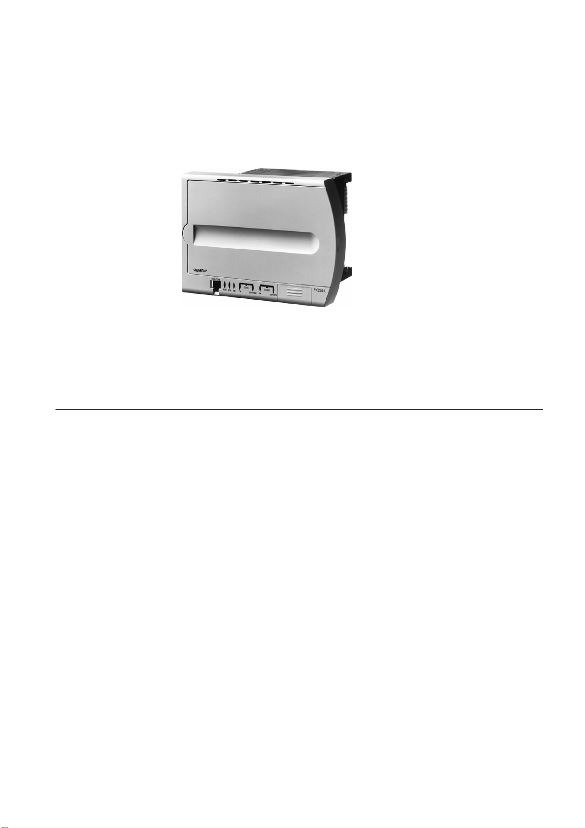
Siemens DESIGO PX -U Series User manual
Other Siemens Measuring Instrument manuals

Siemens
Siemens Sitrans F Series User manual

Siemens
Siemens SENTRON PAC2200 User manual

Siemens
Siemens SITRANS FUH1010 User manual

Siemens
Siemens SITRANS F M MAG 3100 User manual

Siemens
Siemens 3KF9010-1AA00 User manual

Siemens
Siemens SIPROCESS GA700 User manual

Siemens
Siemens SITRANS F M MAGFLO User manual

Siemens
Siemens 13-xx-ST-SBT Series Operation manual

Siemens
Siemens MD-P1 User manual

Siemens
Siemens FIDAMAT 5E User manual

Siemens
Siemens SITRANS F US SONO 3300 User manual

Siemens
Siemens Milltronics BW500 Instruction sheet

Siemens
Siemens CSI Host Driver User manual

Siemens
Siemens SITRANS F US User manual

Siemens
Siemens SITRANS FUP1010 User manual

Siemens
Siemens SENTRON ATC6300 User manual

Siemens
Siemens FS20 User guide

Siemens
Siemens SITRANS F M MAG 3100 User manual

Siemens
Siemens SIPROCESS GA700 User manual

Siemens
Siemens SITRANS F User manual