Bender TM800 User manual

Manual
EN
TM800_D00165_00_M_XXEN/06.2015
TM800
Alarm indicator and operator panel
Software version: 4.0x

Bender GmbH & Co. KG
P.O. Box 1161 • 35301 Gruenberg • Germany
Londorfer Straße 65 • 35305 Gruenberg • Germany
Tel.: +49 6401 807-0 • Fax: +49 6401 807-259
© Bender GmbH & Co. KG
All rights reserved.
Reprinting only with permission
of the publisher.
Subject to change!
Photos: Bender archives.

3
Table of Contents
TM800_D00165_00_M_XXEN/06.2015
1. How to get the most out of this manual ............................................................. 7
1.1 How to use this manual ......................................................................................................... 7
1.2 Explanation of symbols and notes ..................................................................................... 7
2. Safety instructions .................................................................................................. 9
2.1 Intended use .............................................................................................................................. 9
2.2 Qualified personnel ................................................................................................................. 9
2.3 General safety instructions ................................................................................................... 9
2.4 Delivery conditions, warranty and liability .................................................................. 10
3. System description .............................................................................................. 11
3.1 MEDICS® ................................................................................................................................... 11
3.2 TM800 features ...................................................................................................................... 12
3.3 Functionality of the TM800 ............................................................................................... 13
3.3.1 LC display ................................................................................................................................. 13
3.3.2 Programmable messages .................................................................................................. 14
3.3.3 History memory ..................................................................................................................... 14
3.3.4 Interfaces .................................................................................................................................. 14
3.3.4.1 BMS bus ............................................................................................................................. 14
3.3.4.2 USB interface .................................................................................................................... 15
3.3.5 Programming and reading the TM800 ......................................................................... 15
3.3.5.1 Connection of the personal computer ................................................................... 15
3.3.5.2 Optional software .......................................................................................................... 15
3.3.6 Firmware versions ................................................................................................................. 15
3.4 Mechanical design ................................................................................................................ 16
3.4.1 Module overview .................................................................................................................. 16
3.4.2 BM800 and BM400 modules ............................................................................................. 16
3.4.2.1 BM800 ................................................................................................................................ 16
3.4.2.2 BM400 ................................................................................................................................ 16
3.4.3 Operating and display modules ..................................................................................... 16
3.4.4 Inputs and outputs ............................................................................................................... 17
3.4.4.1 Digital output 1 ............................................................................................................... 17
3.4.4.2 I/O modules ...................................................................................................................... 17
3.4.5 Individual internal components ...................................................................................... 18

Table of Contents
4TM800_D00165_00_M_XXEN/06.2015
4. Installation and connection ............................................................................... 19
4.1 Installation ................................................................................................................................ 19
4.1.1 Overview of enclosure variants ........................................................................................ 19
4.1.2 Unpacking ................................................................................................................................ 20
4.1.3 Installing the flush-mounting type enclosure with bezel frame (UPB) .............. 21
4.1.4 Installing the flush-mounting enclosure with mounting frame (UPE) ............... 22
4.1.5 Mounting the front plate .................................................................................................... 24
4.1.5.1 Flush-mounting type enclosure with bezel frame (UPB) ................................. 24
4.1.5.2 Flush-mounting type enclosure with mounting frame (UPE) ........................ 25
4.1.6 Installation of the surface-mounting enclosure (AP) ................................................ 26
4.1.7 Opening the front plate ...................................................................................................... 27
4.2 Connection ............................................................................................................................... 28
4.2.1 Connection details ................................................................................................................ 28
4.2.2 Modules and connections of the TM800 (connection example) .......................... 29
4.2.3 BMS-bus connection ............................................................................................................ 31
4.2.3.1 Terminating resistor ....................................................................................................... 31
4.3 Examples for connection and address assignment .................................................. 32
4.3.1 Address settings and their meaning ............................................................................... 35
5. Commissioning and testing ............................................................................... 37
5.1 Tests before switching on ................................................................................................... 38
5.2 Tests after switching on ...................................................................................................... 39
5.3 Make settings (parameterisation) .................................................................................... 39
5.3.1 Settings at the TM800 .......................................................................................................... 40
5.3.2 Settings using the TMK-SET software ............................................................................. 41
5.3.3 Tests after parameter setting ........................................................................................... 42
5.4 Periodic verification and service ...................................................................................... 43
5.4.1 Periodic verification .............................................................................................................. 43
5.4.2 Service ........................................................................................................................................ 44
5.4.3 Maintenance ............................................................................................................................ 44
6. Troubleshooting ................................................................................................... 45
6.1 Error messages ........................................................................................................................ 45
6.2 Malfunctions ............................................................................................................................ 46
6.3 Replace flash memory .......................................................................................................... 48
7. Operation ............................................................................................................... 49
7.1 Operator control and display elements ......................................................................... 49
7.2 Quick reference guide .......................................................................................................... 50

Table of Contents
5
TM800_D00165_00_M_XXEN/06.2015
7.2.1 Display under normal operating condition ................................................................. 50
7.2.2 Display during fault condition ......................................................................................... 51
7.2.3 Test function ........................................................................................................................... 52
8. Menu mode: Operation and setting ................................................................. 55
8.1 Switching on and calling the main menu .................................................................... 55
8.2 Menu overview diagram .................................................................................................... 56
8.3 Main menu functions ........................................................................................................... 57
8.4 The main menu ...................................................................................................................... 57
8.4.1 Exit .............................................................................................................................................. 57
8.4.2 Menu2: Values ........................................................................................................................ 57
8.4.3 Menu 3: History ...................................................................................................................... 57
8.4.4 Menu 4: Settings .................................................................................................................... 59
8.4.4.1 Exit ....................................................................................................................................... 59
8.4.4.2 Settings menu 2: Alarm addresses ........................................................................... 59
8.4.4.3 Settings menu 3: Test addresses .............................................................................. 60
8.4.4.4 Settings menu 4: Measurement addresses ........................................................... 61
8.4.4.5 Settings menu 5: Digital inputs ................................................................................. 61
8.4.4.6 Settings menu 6: Buzzer (and LED) .......................................................................... 63
8.4.4.7 Settings menu 7: Common reset .............................................................................. 63
8.4.4.8 Settings menu 8: Clock ................................................................................................. 63
8.4.4.9 Settings menu 9: Language ........................................................................................ 64
8.4.4.10 Settings menu 10: Interface ....................................................................................... 65
8.4.4.11 Settings menu 11: Relays ............................................................................................ 65
8.4.4.12 Settings menu 12: Password ...................................................................................... 66
8.4.4.13 Settings menu 13: Service menu .............................................................................. 66
8.4.5 Menu 5: Control ..................................................................................................................... 67
8.4.5.1 Exit ....................................................................................................................................... 67
8.4.5.2 Control menu 2: Reset (AlarmClear) ........................................................................ 67
8.4.5.3 Control menu 3: EDS Start/Stop ............................................................................... 67
8.4.5.4 Control menu 4: Test communication .................................................................... 68
8.4.5.5 Control menu Reset mode .......................................................................................... 68
8.4.6 Menu 6: External devices .................................................................................................... 68
8.4.7 Menu 7: Info ............................................................................................................................ 70
8.5 Overview of setting options .............................................................................................. 71
9. Technical data ....................................................................................................... 73
9.1 Technical data BM800/BM400 modules ....................................................................... 73
9.1.1 Standards, approvals and certifications ........................................................................ 74
9.2 Dimensions ............................................................................................................................. 75

Table of Contents
6TM800_D00165_00_M_XXEN/06.2015
9.2.1 Surface-mounting enclosure, aluminium, silver matt anodised .......................... 76
9.3 Ordering details ...................................................................................................................... 76
10. Internal components and modules ................................................................ 77
10.1 BM800 and BM400 module ................................................................................................ 77
10.1.1 BM800 and BM400 dimensions ........................................................................................ 77
10.2 Operating and display module BI800S .......................................................................... 78
10.2.1 BI800S dimensions ................................................................................................................ 78
10.2.2 Wiring diagram BI800S ........................................................................................................ 78
10.2.3 Technical data BI800S ......................................................................................................... 78
10.2.4 Ordering information BI800S ............................................................................................ 79
10.3 Operating and display module BI71S ............................................................................. 80
10.3.1 BI71S dimensions ................................................................................................................... 80
10.3.2 Wiring diagram BI71S ........................................................................................................... 80
10.3.3 Technical data BI71S ............................................................................................................. 81
10.3.4 Ordering information BI71S ............................................................................................... 81
10.4 Operating and display module BI72S ............................................................................. 82
10.4.1 BI72S dimensions ................................................................................................................... 82
10.4.2 Wiring diagram BI72S ........................................................................................................... 82
10.4.3 Technical data BI72S ............................................................................................................. 83
10.4.4 Ordering information BI72S ............................................................................................... 83
10.5 I/O module BMI8/8 ................................................................................................................ 84
10.5.1 BMI8/8 dimensions ............................................................................................................... 84
10.5.2 Wiring diagram BMI8/8 ........................................................................................................ 84
10.5.3 Technical data BMI8/8 .......................................................................................................... 85
10.6 I/O module BMI8/4 and BMI0/4 ........................................................................................ 86
10.6.1 BMI8/4 and BMI0/4 dimensions ....................................................................................... 86
10.6.2 Wiring diagram BMI8/4 and BMI0/4 ............................................................................... 86
10.6.3 Technical data BMI8/4 and BMI0/4 .................................................................................. 87
INDEX ...........................................................................................................................89

7
TM800_D00165_00_M_XXEN/06.2015
1. How to get the most out of this manual
1.1 How to use this manual
This operating manual describes the TM800 alarm indicator and operator panel with the software
version specified on the title page. The functions and processes described may vary from those fea-
tured in other versions. This manual is intended for qualified personnel working in electrical engi-
neering and electronics and in particular for those designing, installing and operating electrical
equipment in medical locations.
Chapter "Operation" on page 49 can also be used as a quick reference guide by medical personnel.
Before using the devices, please read this operating manual, the supplement entitled "Important
safety instructions for Bender Products" and the instruction leaflets supplied with the individual sys-
tem components. Keep this document in an easily accessible location near to the devices.
Should you have any further questions, please contact our Technical Sales department. We are also
happy to provide on-site service. Contact our Service Department for more information.
Although great care has been taken in the drafting of this operating manual, it may nevertheless
contain errors and mistakes. Bender cannot accept any liability for injury to persons or damage to
property resulting from errors or mistakes in this manual.
1.2 Explanation of symbols and notes
The following terms and symbols are used to denote hazards and instructions in Bender documen-
tation:
The signal word indicates that there is a high risk of danger that will result in
death or serious injury if not avoided
This signal word indicates a medium risk of danger that can lead to death or se-
rious injury, if not avoided.
This signal word indicates a low level risk that can result in minor or moderate
injury or damage to property, if not avoided.
This symbol denotes information intended to assist the user in making optimum
use of the product.
DANGER
WARNING
CAUTION

9
TM800_D00165_00_M_XXEN/06.2015
2. Safety instructions
2.1 Intended use
In terms of human/machine interface, alarm indicator and operator panels play a crucial role. Their
task is to take system information and transform it into clear instructions, particularly in the event of
critical operating situations. The flexible TM800 alarm indicator and operator panels provide solu-
tions that meet the requirements of modern medical facilities as well as industrial and functional
buildings. They are used for
the display and visualisation of operating status, warning and alarm messages
central operation and parameterisation of BMS bus devices (BMS = Bender Measuring Device
Interface)
the output of visual and audible warning messages
the display of measured values from Bender monitoring systems with BMS interface, such as
MEDICS®, RCMS or EDS
In addition, they are used for the display, control and operation of
operating theatre tables
equipment for supplying medical gases
battery-supported central power supply systems (BSV systems)
air conditioning and ventilation systems
room lighting
communication equipment
and third-party systems.
All technical devices installed in one alarm indicator and operator panel constitute a technology cen-
tre in the relevant room.
Please heed the limits of the area of application indicated in the technical specifications. Use which
deviates from or is beyond the scope of these technical specifications is considered non-compliant.
Use for the intended purpose also includes:
Device-specific settings compliant with local equipment and operating conditions.
The observation of all information in the operating manual.
Compliance with test intervals.
2.2 Qualified personnel
Only appropriately qualified personnel may work with the Bender devices. Personnel who are famil-
iar with the installation, commissioning and operation of the equipment and have undergone ap-
propriate training are considered qualified. Personnel must have read this manual and understood
all instructions relating to safety.
2.3 General safety instructions
Bender devices are designed and built in accordance with the state of the art and accepted rules in
respect of technical safety. However, the use of such devices may introduce risks to the life and limb
of the user or third parties and/or result in damage to Bender devices or other property. Only use

Safety instructions
10 TM800_D00165_00_M_XXEN/06.2015
Bender devices:
–Asintended
– In perfect working order
– In compliance with the accident prevention regulations and guidelines applicable at the
location of use
Eliminate all faults immediately which may endanger safety.
Do not make any unauthorised changes and only use replacement parts and optional accesso-
ries purchased from or recommended by the manufacturer of the devices. Failure to observe
this requirement can result in fire, electric shock and injury.
Reference signs must always be clearly legible. Replace damaged or illegible signs immediately.
Make sure that the dimensions of the BSV (battery-supported safety power supply), the genera-
tor set and the whole wiring are adequate. The applicable national and international standards
must be observed here. Only in this way selective operation of safety devices can be achieved
and a high degree of safety in case of overload and short circuit can be ensured.
2.4 Delivery conditions, warranty and liability
The conditions of sale and delivery set out by Bender apply. Conditions of sale and delivery can be
obtained from Bender in printed or electronic format.

11
TM800_D00165_00_M_XXEN/06.2015
3. System description
3.1 MEDICS®
The TM800 alarm indicator and operator panel is an integral component of the MEDICS®system.
MEDICS®is an intelligent system that guarantees safe power supply in medical locations.
Example of a section of a hospital with the MEDICS®system
Legend to the illustration above
MK… Alarm indicator and test combination
RCMS… Residual current monitoring system for TN-S systems
SMI472 Signal converter for third-party technical equipment (e.g. med. gases, BSV (battery-
supported systems)
TM… Alarm indicator and operator panel
UFC107E… Changeover and monitoring module for IT systems with EDS insulation fault location system
UMC107E… Changeover and monitoring module for IT systems
UMC710D… Changeover module for main distribution boards
USC710D… Control module for changeover modules (preferably in main distribution boards)
SCADA system (Supervisory Control and Data Acquisition)

System description
12 TM800_D00165_00_M_XXEN/06.2015
MEDICS®includes:
Single and three-phase monitoring modules. MEDICS®system modules are, for example:
UMC…, USC…, UFC… and/or EDS… insulation fault location systems
Display and operating units such as TM… alarm indicator and operator panels or MK… alarm
indicator and test combinations
Communication between these components via the BMS bus (two-wire connection).
The connection of third-party technical systems by means of protocol converters (gateways) or
via digital inputs and relay outputs.
The real strength of MEDICS®is to be found in communication between all involved components and
the resulting information provided to the user. The functionality of the equipment is continuously
monitored. Operating states, irregularities, faults and equipment failures are displayed. This means
high operational reliability of the installation for the user.
3.2 TM800 features
On its backlit LC display, the TM800 displays messages from all BMS-bus devices and digital inputs
assigned via alarm addresses. As well as being used as a standalone indicator, the TM800 also sup-
ports parallel indication in different rooms. In the event of an alarm message, the yellow LED "WARN-
ING" or the red LED "ALARM" lights up and the message appears on the LC display in plain text
format. At the same time there is an audible signal (can be acknowledged/muted). If a second mes-
sage is received whilst the first is still pending, the audible signal will sound again and the messages
will appear alternately on the LC display. The address of the device triggering the alarm can also be
called up. The audible signal sounds again once a configurable period of time has elapsed (repetition
can be deactivated). Illuminated pushbuttons can be programmed to signal alarms and operating
states or for programming operating information. Operator actions or messages can be output via
digital outputs.
Internal device parameters (alarm addresses, test addresses…) and the parameter setting of EDS-
and RCMS systems can be accessed via the menu system. TM800 can be also be used as a master de-
vice in installations with a number of IT and EDS systems.
The test button can be used to check the function of the associated devices such as insulation mon-
itoring devices, LIM (Line Isolation Monitors) or GFCI (Ground Fault Circuit interrupters). The message
is output only on the TM800 on which the test button "TEST" was pressed. The test and its individual
evaluations are carried out sequentially. Finally, a message appears indicating either a successful test
or a fault.
TM800 features:
Display, control and operation of Bender monitoring systems and third-party systems
Backlit clear LC text display (4 x 20 characters, 8 mm)
Additional text with specific information for technical and medical personnel can be displayed
LEDs in traffic light colours: 3 LEDs for optical differentiation of messages
Predetermined standard texts in 21 languages for Bender MEDICS® systems
1000 freely programmable message texts (with TMK-SET PC software)
Audible alarm (can be acknowledged or muted)
Easy parameterisation:
– with a personal computer (USB interface, BMS bus): TM800, MK800, EDS46x, EDS47x,
EDS49x, RCMS460, RCMS470, RCMS490
– via menu: TM800 basic parameters

System description
13
TM800_D00165_00_M_XXEN/06.2015
History memory with real-time clock to store 1000 warning and alarm messages
Variable operator and display modules with a freely programmable function
Easy integration with third-party systems, because operating theatre table controls, medical
gases, intercom systems are behind a closed foil surface
Control of third-party systems by flexible I/O modules with galvanic separation
Alarm LED at each input/output for fast diagnosis
Functions can be easily extended by adding I/O modules
Clearly defined structure thanks to an external and internal bus
Non-reflecting, multi-coloured foil surface
Optionally available with an antibacterial foil surface
3.3 Functionality of the TM800
3.3.1 LC display
The backlit features four lines of 20 characters. It assists medical and technical personnel during the
decision-making process with information that is always clear and unambiguous. Every alarm mes-
sage comprises three lines which appear spontaneously and three additional lines which can be dis-
played at the touch of a button. The fourth line contains status information (the number of
messages, test procedures, menu information).
Below the text display, three LEDs are arranged. They indicate: normal operation (green), warning
(yellow) or alarm messages (red).
Five buttons are available to acknowledge or to mute alarm and warning messages, for testing the
assigned devices and for the menu system.
Betrieb Warnung Störung

System description
14 TM800_D00165_00_M_XXEN/06.2015
3.3.2 Programmable messages
Standard message texts can be activated by enabling alarm addresses. These texts are available in
21 national languages. Alarm addresses can be enabled via the device menu system (without per-
sonal computer). Individual message texts, each comprising 6 lines à 20 characters can be pro-
grammed with the TMK-SET software. Up to three outputs can be assigned to each alarm.
An LED (yellow or red) and an audible signal can be assigned to each message. For this purpose, the
PC is connected to the USB interface or BMS bus (RS-485). In addition to the buzzer, a relay can be
activated that enables, for example, an alarm horn sound in a loud environment.
3.3.3 History memory
Warnings and alarms with date and time stamp are automatically written to the history memory.
1000 text messages can be stored. Each subsequent message overwrites the oldest message in the
history memory (message 1001 will overwrite message 1 etc.). The history memory can be read out
via the operating menu or the TMK-history PC software.
3.3.4 Interfaces
Alarm indicator and operator panels feature different interfaces, for communication with third-party
systems and/or MEDICS®components:
–InternalBMSbus
–ExternalBMSbus
–USBinterface
3.3.4.1 BMS bus
The BMS bus system (BMS=Bender Measuring Device Interface) guarantees high operational reliabil-
ity:
Based on the tried and tested industrial standard RS-485
A self-contained system - not influenced by third-party systems
Redundant master function and data transmission (internal and external bus)
Mutual device monitoring
Open, thanks to defined interfaces, e.g. OPC server
Internal BMS bus
The internal BMS bus is used for communication with BMS bus devices,
– e.g. modules like UMC…, UMA…, UFA…, UFC…, LFC…, ATICS®
– or devices like RCMS…, EDS…, SMI…, SMO…, MK800…, TM800
Up to 30 devices can be connected to each internal bus line (in combination with the DI-1PSM re-
peater up to 150). One address is assigned to each bus device. Address 1 is assigned to the TM800
alarm indicator and operator panel which represents the master on the internal bus.
If the external BMS bus is switched off, addresses 2…150 (slave) can be selected on the internal bus.

System description
15
TM800_D00165_00_M_XXEN/06.2015
External BMS bus
The external BMS bus enables communication with other TM800 alarm indicator and operator pan-
els, SMI472-12 or BMS-OPC servers. The master function is cyclically passed to the subsequent mas-
ter on the external bus. The TM800, with address 1, however, takes over some special tasks:
– As a "master clock", it synchronises the time of all devices on the internal BMS bus
– It ensures that the required supply voltage is available on the external BMS bus.
Messages can be displayed on any TM800 alarm indicator and operator panel via the external BMS
bus. The PC software TMK-SET is used to assign the messages accordingly.
A personal computer is recommended to be connected via the external BMS bus to the TM800 alarm
indicator and operator panel. Any information of the TM800 panels connected to the external BMS
bus can be displayed and set at a central point. If the personal computer does not feature an RS-485
interface, an RS-232/RS-485 converter DI-2 or a USB/RS-485 converter DI-2USB will be required.
3.3.4.2 USB interface
A personal computer can also be connected to the TM800 via the USB interface using a standard-USB
device cable (type A/type B). To access the USB interface plug, open the front plate.
Only the connected TM800 can be read out and set via the USB interface.
3.3.5 Programming and reading the TM800
3.3.5.1 Connection of the personal computer
Connect the TM800 to a personal computer:
directly via the USB interface or
via an RS-232/RS-485 converter DI-2 or a USB/RS-485 converter DI-2USB to the internal or exter-
nal BMS bus.
3.3.5.2 Optional software
You can use the PC software TMK-SET to read, display and change the TM800 settings.
You can use the PC software TMK-History to read the history memory of the TM800 (download
from http://www.bender-de.com).
BMS-OPC server
3.3.6 Firmware versions
The TM800 is controlled by an internal software (firmware).
All devices sharing one external BMS bus must be equipped with compatible
software versions. The following software versions are required:
TM V 4.0 or higher
SMI472 V 2.03 or higher
All devices must be set to the same baud rate.

System description
16 TM800_D00165_00_M_XXEN/06.2015
3.4 Mechanical design
3.4.1 Module overview
The TM800 alarm indicator and operator panels are based on a modular design. The appropriate
combination of modules will be made by Bender so that the user is not unnecessarily burdened with
planning details. This chapter provides a summary of the applicable modules:
BM800 Module for TM800 alarm indicator and operator panel
BM400 module like BM800, but without an LC display and control buttons
BI… operating and display modules each with five illuminated pushbuttons
BMI… I/O modules (digital inputs, relay outputs, open collector outputs)
Individual components (remote operating table control, intercom systems…)
3.4.2 BM800 and BM400 modules
3.4.2.1 BM800
Module for a TM800 alarm indicator and operator panel with LC display. BM800 features:
– LC display (without a front foil, because this is included already in the front plate of TM800)
– one operating LED, warning and alarm LED each as common alarm LEDs
– 5 control buttons
– Interfaces 2 x RS-485, 1 x USB, 2 x I²C
–Buzzer
3.4.2.2 BM400
BM400 is a module similar to BM800, but without LC display and control buttons. These operating
and display modules together with digital I/O modules can be configured to form indicator and op-
erator panels.
3.4.3 Operating and display modules
The operating and display modules consist of 5 elements. Depending on the panel type, different
numbers of modules are available (also see "Internal components and modules" on page 77ff).
Type Characteristics
BI800S Operating and display elements to expand the BM800/BM400 modules. 16 BI800S
modules can be controlled via I²C bus. One individual function (switch, button, LED etc.)
can be assigned to each element.
BI71S Operating and display elements without an I²C bus:
5 illuminated pushbuttons, 5 potential free changeover contacts, max. AC 250 V/8 A.
BI72S Operating and display elements without an I²C bus:
5 illuminated pushbuttons, 5 potential free changeover contacts, max. AC 24 V/0.9 A

System description
17
TM800_D00165_00_M_XXEN/06.2015
3.4.4 Inputs and outputs
Digital inputs and outputs as well as relay outputs are available for the control and indication of dif-
ferent technical equipment. The I/O modules are controlled via I²C bus.
The digital inputs are designed for a voltage of AC/DC 0…30 V (HIGH=10…30 V; LOW=0…2 V). In
practice, these digital inputs are controlled via an internal or external voltage and potential-free con-
tacts (N/C or N/O operation, selectable). The voltage required for these inputs can be supplied by the
built-in power supply unit. The behaviour of the alarm contact at the digital input (N/O contact or N/
C contact) can be assigned via this PC software. That means that the hardware of the alarm indicator
and operator panel does not need to be changed in case of subsequent changes of the contact be-
haviour.
Digital inputs or outputs (potential free relay contacts or open collector outputs) are controlled by
warning or alarm messages, via operating and display modules or the digital inputs. A message, a
digital input or an illuminated pushbutton can be assigned to a relay output via the PC software
TMK-SET.
The I/O modules are snapped on a DIN rail in the flush-mounting box separately from the display and
the pushbutton panels. So the system can easily be expanded. Each input and output provides an
alarm LED so that the status is visible at a glance for the technical staff.
3.4.4.1 Digital output 1
When an I/O module BMI8/8, BMI8/4 or BMI0/4 is built in, the first output can be programmed indi-
vidually. It can be used for system functions (see "Settings menu 11: Relays" on page 65). The output
switches when:
– an internal TM800 device error is recognised
– the test button is pressed (relay will be activated for approx. 1.5 s)
– a device failure is recognised on the BMS bus,
– any warning or alarm message occurs (common alarm)
– the buzzer sounds (relay is activated when buzzer sounding)
The output can also be programmed via TMK-SET like all other outputs.
3.4.4.2 I/O modules
TM800 alarm indicator and operator panels offer safe separation according to
IEC 60664 between the relay contacts and the electronics, interface outputs, dig-
ital inputs and among each other.
Type Characteristics
BMI8/8 8 digital inputs, 8 open collector outputs
The open collector outputs are capable of driving a load of up to 15 W at an operating
voltage of 24 V. They feature flyback diodes for the connection of relays.

System description
18 TM800_D00165_00_M_XXEN/06.2015
3.4.5 Individual internal components
In addition to the operating functions activated via operating and display modules, often complete
operating units from a third-party manufacturer are integrated into the alarm indicator and operator
panel. Typical examples are operating table controls or intercom systems. These modules are inte-
grated in the alarm indicator and operator panels by Bender so that an aesthetically attractive func-
tional solution is available, documented by the official release of the manufacturer. The required
connections are made in accordance with the specifications of the respective manufacturer.
Typical examples of third-party systems used in medical locations
BMI8/4 8 digital inputs, 4 relay outputs
The digital outputs correspond to those of the BI8/8 module. The potential-free output
relays feature one changeover contact eachAC 250 V, 5 A (AC1).
BMI0/4 Expansion for BMI8/4 by 4 relay outputs. The module BMI0/4 can only be used in com-
bination with the BMI8/4 module. The potential-free output relays feature one change-
over contact each AC 250 V, 5 A (AC1).
Med. gases Intercom systems Operating theatre
light
Operating theatre
table
Dräger Digicom-Scanvest ALM Maquet
Gehrke Berchtold Trumpf
Schneider Dräger
Stentofon Haraeus
Telecom Behnke
Intercom system – Digicom Dräger Monitor 3G
Type Characteristics

19
TM800_D00165_00_M_XXEN/06.2015
4. Installation and connection
4.1 Installation
4.1.1 Overview of enclosure variants
The design of the alarm indicator and operator panels is based on the individual customer require-
ments in terms of interior design and the architect's and constructor's needs. In addition to the basic
versions also room-high stainless-steel alarm indicator and operator panels or other versions are
available.
The foil surface is completely closed, i.e. there are no screws needed for fixing the front plate. The
panel is easy to clean so that a high standard of hygiene is guaranteed. For additional protection, the
front panel surface can also be delivered with antibacterial surface.
Flush-mounting type enclosure with bezel frame (UPB)
A gap of up to 12 mm between the flush-mounted enclosure and the wall can be concealed by a bez-
el frame made of anodised aluminium. This version is recommended to be used for wallpapered
walls or walls with non-standard tiles, for example.
Flush-mounting type enclosure with mounting frame (UPE)
The mounting frame permits accurate and close wall mounting. The mounting frame is made of an-
odised aluminium. The mounting frame version is preferably used where the enclosure is required
to fit exactly the dimension of the tiles.

Installation and connection
20 TM800_D00165_00_M_XXEN/06.2015
Surface-mounting enclosure (AP)
The anodised surface-mounting enclosure is suitable for both pure surface-mounting and for partial-
ly recessed mounting. The enclosures can be supplied with a depth of 90, 150 and 210 mm.
The support frame inside the flush-mounted or surface-mounted case is fitted with a long-term elas-
tic seal in order to avoid the ingress of cleaning agents into the panel. Depending on the size, the
front plate is connected to the flush mounting or surface mounting enclosure by two or more stable
hinges. This guarantees easy installation of the alarm indicator and operator panel.
All necessary modules and display elements are permanently fixed to the front plate using threaded
bolts or mounting frames. The front plate is connected with the mounting plate via a flexible spiral
hose that is fixed on both sides with cable clips. The technical equipment and systems are connected
to a terminal board that is fixed on a mounting plate. The power supply unit for the alarm indicator
and operator panel is also located on this mounting plate. The mounting plate can easily be disman-
tled. That allows the flush-mounting or surface-mounting enclosure to be installed prior to the final
assembly stage. Cable connections between the front plate and the terminal board also do not need
to be disconnected.
With the exception of the mounting plate no other components are fixed to the baseplate of the
flush-mounting/surface-mounting enclosure, allowing sufficient room for installation.
4.1.2 Unpacking
Unpack all the parts supplied with the system. Do not use sharp-edged tools that may damage the
content of the packaging.
Compare your order with our delivery note to check that you have received all products in full. The
article numbers printed on the nameplates simplifies the identification of the devices.
Check all parts supplied for any evidence of damage in transit. Devices damaged
in transit must not be used. If a device is damaged, please contact Bender. Details
of who to contact are indicated on the delivery document.
Before using devices that have been stored at low temperates: Leave the devices
to stand for 3 to 4 hours at room temperature before connecting the power sup-
ply. A change in temperature from cold to warm will result in condensation on all
device components. Putting damp devices into operation risks damaging elec-
trical components and there is a danger of electric shock on contact.
WARNING
WARNING
Table of contents
Other Bender Control Panel manuals
Bender
Bender COMTRAXX CP9 Series User manual
Bender
Bender FP200 User manual
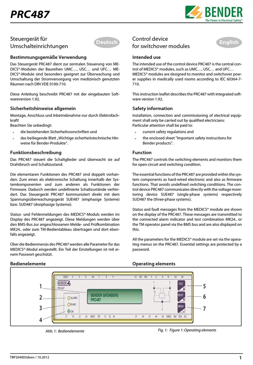
Bender
Bender PRC487 User manual

Bender
Bender COMTRAXX CP9 Series User manual

Bender
Bender COMTRAXX CP9 Series User manual
Bender
Bender COMTRAXX CP9 Series User manual
Bender
Bender COMTRAXX CP305 User manual
Bender
Bender COMTRAXX CP305 User manual

Bender
Bender COMTRAXX CP9 Series User manual

Bender
Bender COMTRAXX CP9 Series User manual

