DEVA Deva018 User manual
Deva018 Single Axis Sine-Wave Interpolator User’s Manual
V2.0
Deva Electronic Controls Limited | 52 Woodside Business Park | Birkenhead | Wirral | CH41 1EL
Phone: +44 (0)151 647 3222 | Fax: +44 (0)151 647 4511 | Email: [email protected] | Website: www.deva.co.uk
CONTENTS:
•Overview
•Installation and Usage
Deva018 Sine-Wave Interpolator User’s Manual
SUPPORT:
For additional downloadable Support
Documentation, please visit
www.deva.co.uk/support-downloads
SIGNAL CONVERSION & GENERATION

© Deva Electronic Controls Ltd 2021
All information within this document is given in good faith by Deva Electronic Controls Ltd. Deva Electronic
Controls Ltd shall not be liable for any loss or damage, howsoever arising, that may be attributed to errors
within, or omissions from, this document, nor for the use of, or application of, the information provided
herein.

Page i
Deva018 Single Axis Sine-Wave Interpolator User’s Manual Contents
1Overview ...................................................................................... 1
1.1 About this Manual ..........................................................................................1
1.2 Deva018 Features ..........................................................................................1
1.2.1 Facilities.............................................................................................................................. 1
2Installation and Usage ................................................................... 3
2.1 Connections...................................................................................................3
2.2 Test point connector ......................................................................................4
2.3 Configuration Solder Pads ..............................................................................4
2.3.1 Example settings ................................................................................................................. 5
2.4 018-BRK1 Breakout test board for 018 setup....................................................6


Page 1
Deva018 Single Axis Sine-Wave Interpolator User’s Manual Overview
«Hder_Sect_Title_1»
1Overview
1.1 About this Manual
This manual covers the Deva018 Single Axis Sine Wave Interpolator and discusses features
and potential applications.
1.2 Deva018 Features
The Deva018 Single Axis Sine Wave Interpolator has been designed for use in motion and
control applications using a PC based system. It can be used for a wide range of
applications, such as manual Coordinate Measuring Machines (CMMs), automation and
process control, control system diagnostics, metrology and data acquisition.
This manual describes the installation/configuration of Deva018 and the facilities it offers.
For information regarding its use in conjunction with other Deva products, please refer to the
relevant User’s Manual/Programming Guide.
Note: Software support is an ongoing activity; if support for a particular application or
operating system is not detailed in our documentation as provided, please contact
1.2.1 Facilities
•Accepts 1Vpp or 11µA signals
•Input range 0.6Vpp - 1.2Vpp or 5µA - 16µA
•Selectable interpolation factor: 10, 20, 50, 100
•Handles marker/index channel
•Maximum input frequency 125kHz
•Maximum output frequency 5MHz
•RS422 line driver output


Page 3
Deva018 Single Axis Sine-Wave Interpolator User’s Manual Installation and Usage
2Installation and Usage
The Deva018 single axis sine-wave interpolator can accept a variety of input signals,
including 11µA or 1Vpp differential sine / cosine signals and produce RS422 differential
square wave quadrature signals. The interpolation factor may be set to 10, 25, 50 or 100
times. For 1Vpp the inputs may be terminated with on board 120ohm resistors. The
maximum input rate is 125kHz and the maximum output count rate is 5MHz using x10
interpolation.
The Deva018 operates from +5V, which may be supplied either from the input or output
connector.
The output connector is pin to pin compatible with all Deva’s encoder interface and motion
control products. All unused pins are passed through from input to output.
2.1 Connections
The following table lists the input and output connection for the Deva018.
Sine Wave Input
Square-wave output
15-way HD female
Signal
15 -way HD male
Signal
Test Connections
Pin 1
Ain
Pin 1
Aout
Oscilloscope nA
Pin 2
Bin
Pin 2
Bout
Oscilloscope B
Pin 3
nTEST
Pin 3
nTEST
0V
Pin 4
Min
Pin 4
Mout
Pin 5
**
Pin 5
**
Pin 6
nAin
Pin 6
nAout
Oscilloscope A
Pin 7
nBin
Pin 7
nBout
Oscilloscope nB
Pin 8
**
Pin 8
**
Pin 9
nMin
Pin 9
nMout
Pin 10
**
Pin 10
**
Pin 11
*(+12V for Deva023)
Pin 11
*(+12V for Deva023)
+12V as required
Pin 12
+5V
Pin 12
+5V
+5V
Pin 13
0V
Pin 13
0V
0V
Pin 14
*
Pin 14
*
Pin 15
*
Pin 15
*
* Connected directly from input to output, no internal connection. The Pin 11 pass-through may be used to take
+12V from Deva001, Deva037 or Deva004 via Deva018 to Deva023.
** Connected directly from input to output, +5V pull up present. If used, do not exceed 0V to +5V range.
When connecting single-ended signals it is important to connect the nAin/nBin/nMin signals
to a suitable reference point. For example, if the scale outputs a 2Vpp signal on a 2.5V offset
then the nAin/nBin/nMin inputs should be connected to the 2.5V scale reference voltage.
Important: If to be used with the Deva023 pre-amp, the Deva018 must be configured for
voltage mode and A,B termination must be disabled.
Page 4
Installation and Usage Deva018 Single Axis Sine-Wave Interpolator User’s Manual
2.2 Test point connector
If tuning of the reader head is required, it is possible to enable test mode by connecting pin 3
of either connector to 0V. In test mode pins 1,2,6 & 7 of the output connector will provide the
buffered A and B signals. All four outputs should be 0.5Vpp and biased around 2.5V.
Important : Do not connect the Deva018 to the target controller when test mode is enabled.
The test connections shown above are recommended.
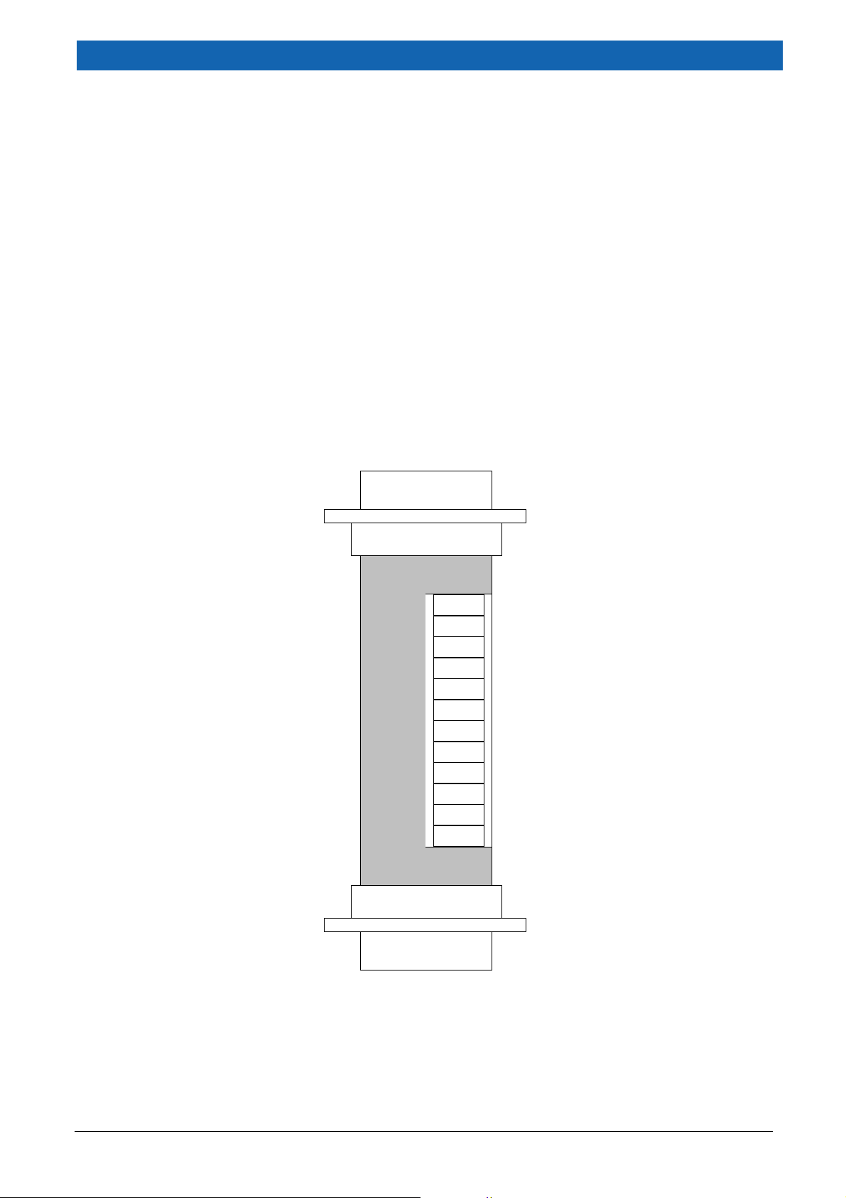
2.3 Configuration Solder Pads
There are eight pairs of solder pads that must be shorted to change the configuration of the
Deva018, as shown in Figure 2.1 and associated tables.
Note: The default configuration is 11µA, x10 interpolation, with no termination and is shown
shaded grey in the tables.
IMPORTANT : These instructions refer to RevD, and later, Deva018 interpolators with serial
numbers from 38228 and onwards.
HD 15-way Female
A term
B term
M term
CFG0
CFG1
CFG2
CFG3
CFG4
HD 15-way Male
Figure 2.1 Deva018 Solder Pad Location

Page 5
Deva018 Single Axis Sine-Wave Interpolator User’s Manual Installation and Usage
Pads CFG0 and CFG1 control the Interpolation factor.
CFG1
CFG0
Factor
x10
X25
X50
x100
Pads CFG2 and CFG3 control the input level.
CFG3
CFG2
Factor
Notes
11µA
1Vpp
2Vpp
MIT1
(Reserved)
When differential voltage signals, such as 1Vpp, are in use, it is typical to terminate the
signals with 120 ohm resistors. Termination is controlled by the following links.
Termination
Link
None
120 ohm
A term
B term
M term
2.3.1 Example settings
11µA
x10
11µA
x50
1Vpp
x100
2Vpp
x10
Deva
023
A term
B term
M term
CFG0
CFG1
CFG2
CFG3
CFG4
Page 6
Installation and Usage Deva018 Single Axis Sine-Wave Interpolator User’s Manual
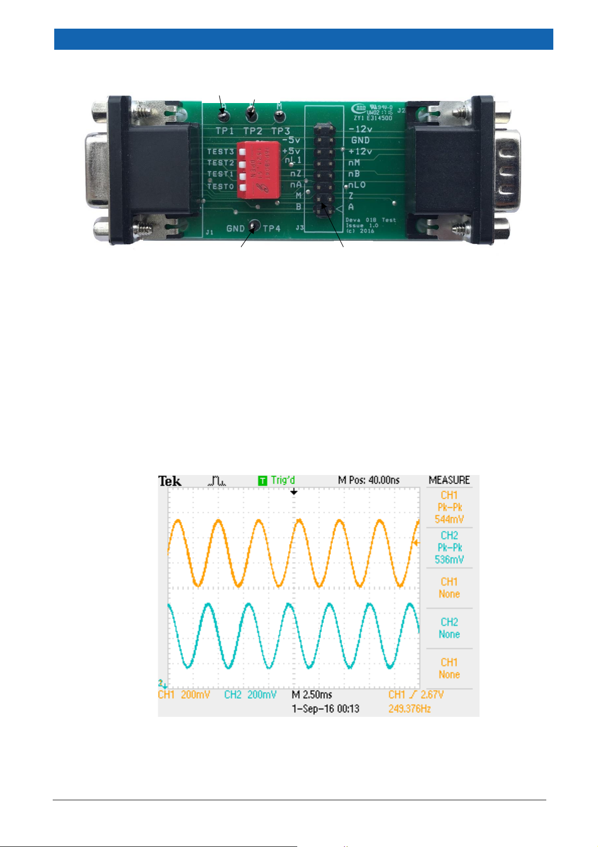
2.4 018-BRK1 Breakout test board for 018 setup.
Figure 2.2 018-BRK1 Breakout test board
The 018-BRK1 test board pictured in Figure 2.2 is available to assist in making test
connection to the Deva 018-1SIN interpolator (Order Code 018-BRK1).
It is inserted in the cable after the 018-1SIN and derives power from the Deva001, Deva004 or
Deva037 in use.
Moving switch TEST0 into the closed / down position will invoke test mode the next time the
018-1SIN power is cycled.
When in test mode, the signals described above will be present on both the A,B test points
(TP1 and TP2) and header J3. Use the GND test point (TP4) for the oscilloscope ground clip.
The nA and nB phases if required can be found on J3.
The image at Figure 2.3 shows typical signals at the A and B test points.
Figure 2.3 Typical Signals at the A and B Test Points
Note : Not all signals indicated, such as the -5V or -12V, will be on J3; it depends on what
controller hardware is in use.
TP1
TP2
TP4
J3

SUPPORT:
For additional downloadable Support
Documentation, please visit
www.deva.co.uk/support-downloads
Deva Electronic Controls Limited | 52 Woodside Business Park | Birkenhead | Wirral | CH41 1EL
Phone: +44 (0)151 647 3222 | Fax: +44 (0)151 647 4511 | Email: [email protected] | Website: www.deva.co.uk
Table of contents
Other DEVA Media Converter manuals


