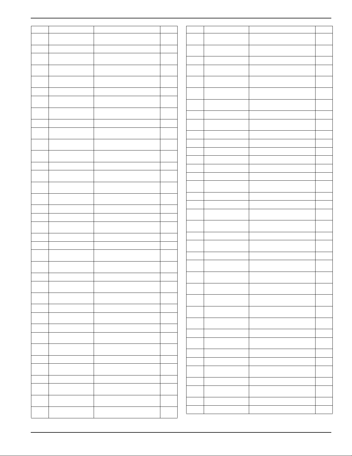
DEWALT 14000 Generator 7
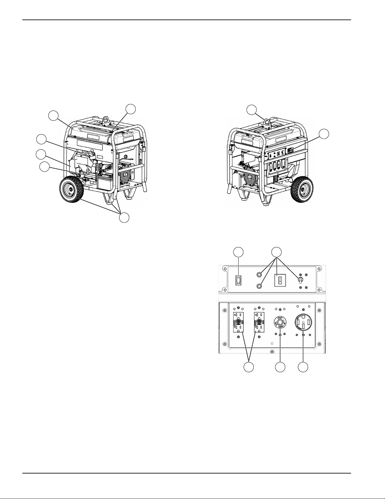
Item Part No. Description Qty.
10L11140ST03 CARRIER DXGN14000
BLACK
1
20L0992 WIRED PANEL DXGN14000 1
310000023679 FUEL TANK ASSEMBLY,
DXGN14000
1
4EHB200CB03Y ENGINE G36 GX630R VXE2
AIR_3
1
50L0442 HEX FLANGED NUT (5/16-
18 SERR ZP)
8
60L0949 CAP FUEL 1
70L0878 BATTERY POST COVER
ELL-TRON 47
1
80L09950ST03 STATOR BRACKET
DXGN14000 BLK
1
90L0829 WASHER (42 X 1.5 X .25) 2
10 0L1014 HONDA MUFFLER X630
DXGN14000
1
11 0L0845 FILLER ON/OFF
FLOOTOOL #720104
1
12 0L0947 FLAT WASHER (5/16 1.13
OD ZP)
2
13 0L2472 CHAIN RING ATTACHMENT 1
14 0L1031 BOLT WHZ (3/8-16 X 1.00
GR5 ZP)
4
15 0L0767 BLK WIRE ASSEMBLY 8GA
19.25 RING/R
1
16 0L0715 RED WIRE 8GA 17.25
RING/R
1
17 0L2477 VINYL HOSE (1/2 ID X 6 LG) 1
18 0L0856 WORM HOSE CLAMP SAE6 1
19 0L0859 FITTING (3/8NPT X 1/2
BARB STR
1
20 0L0858 BALL VALVE 3/8 NPT M/F 1
21 0L0926 OIL DRAIN FITTING GX630 1
22 0L1032 HEX HEAD BOLT (M6-1.0 X
30MM BLK ZDC)
4
23 0L0366 WIRE GREEN/YELLOW
12GA 5.50 GR
1
24 0L2407B FUEL HOSE 8MM X 8 LG 1
25 0L0803 SCREW HSW #10-32 X .50
ZP (NAS
1
26 0L0446 HEX HEAD BOLT(5/16 - 18
X 1.5)
8
27 0L0805 NYLOC NUT (5/16 - 18) 4
28 0L0974 RELEASE PIN (5/16OD X
1.00LG BL)
2
29 0L0809 FLAT WASHER 5/16 W ZP 12
30 0L0711 HEX HEAD BOLT (5/16-18 X
1.00 GR5 ZP)
9
31 0L0440 LOCK WASHER (5/16 ZP
(NASP)
9
32 0L0437 ISOLATOR 7
33 0L0462 STAR WASHER (5/16 EXT
(NASP)
6
34 0L0403 FUEL FILTER 1
35 0L1104 FUEL TANK METAL MOUNT
INSERT
4
36 0L0405 BEZEL FUEL GAUGE W/
PRINTED LEV
1
37 0L0924 SPARK ARRESTOR KIT V-
TWIN
1
38 0L0937 GFCI RECEPTACLE
COVER
2
39 0L1071 RECEPTACLE COVER
TWISTLOCK
1
40 0L0948 COVER RECEP 50A 1
41 0L1102 RUBBER MOUNTING
GROMMET
4
42 0L1116 CARBON CANISTER
BRACKET 1200CC
1
43 0L0396 CIRCUIT BREAKER 20A
125V
2
44 0L0625 CIRCUIT PROTECTOR 30A
DUAL
1
45 0L0846 CIRCUIT BREAKER 50A 1
46 0L1037 IC MODULE ASSEMBLY
DXGN 14000
1
47 0L0808 STRAIN RELIEF FASTENAL 1
48 0L0423 ROCKER SWITCH SPDT 1
49 0L0809 FLAT WASHER (5/16 W ZP) 7
50 0062552SRV MANIFOLD GASKET 2
51 0061393SRV NUT WHZ 8MM 4
52 0L0868 NYLON LANYARD 3/16 2
53 0L10000ST03 WELDED HANDLE ASSEM-
BLY DXGN140 BLK
1
54 0L0822 VINYL J CLAMP 1/2 1
55 0L0870 HANDLE GRIP 2
56 0L0973 HEX HEAD BOLT (3/8 - 16 X
1.75 GR5 BL)
2
57 0L10390ST03 HEAT SHIELD ASSY
DXGN14000 BLK
1
58 0L0854 GROMMET(.88 ID X 1.5OD) 1
59 0L1035 WIRE HARNESS ASSY
DXGN14000
1
60 0062554SRV RECTIFIER 1
61 0L1032 HEX HEAD BOLT (M6-1.0 X
30MM BLK ZDC
1
62 0L0444 HEX HEAD BOLT (5/16-18 X
1.25 GR5 ZP)
1
63 0L0807 BOLT WHZ 5/16-18 X .50 ZP
(NAS)
2
64 0L1111 WHEEL ASSEMBLY12 FLAT
FREE
2
65 0L10110ST03 WHEEL BRACKET ASSY
DXGN140 BLK
2
66 0L10100ST03 FOOT BRACKET
DXGN14000 BLK
2
67 0L0945 RUBBER FOOT 2
68 0L09960ST03 BATTERY HEAT SHIELD
DXGN14 BLACK
1
69 0L0976 COTTER PIN (1/8 X 1.25) 2
70 0L0871 WHEEL SPACER 2
71 0L0980 HEX HEAD BOLT (5/16 - 18
X 2.00 UNC B)
4
72 0L1086 CONNECTOR HOSE 1
73 0L1063 FUEL VALVE HOLDER
INSERT V2
1
74 0L0813 FUEL VALVE 1
75 GU0151 SCREW (M6 X 20 TF) 4
Item Part No. Description Qty.