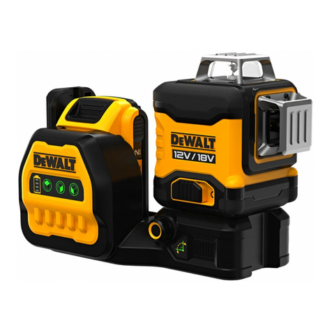
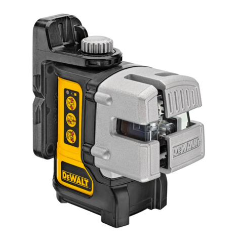
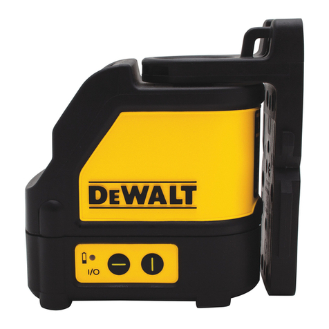
DeWalt DCLE34031 User manual

DCLE34031
TR
www.DeWALT.co.kr

English (original instructions) 7
영어 (원본 설명서) 16

1
Fig. A
1
2
3
4 5
6

2
Fig.B Fig.C
Fig.D Fig.E
71
7
1
8

3
Fig.F
Fig.G
Fig. H
a
b
a
c
a
b
ab
> 33 . (10m)
_
c
b

4
Fig.I
Fig.J
Fig. K
Fig. L
ab
ba
> 30 Ō. (9m)
_
b
c
ba
c
c
a
c
c
g
> 8 . (2.5m)
_
2
d
2
1
23

5
Fig. M
Fig. N Fig. O 10
1
2
3
9

6
Fig. P Fig. Q
Fig. R Fig. S
11
12
13 9
Fig. T

7
ENGLISH
Contents
• Laser Information
• User Safety
• Battery Safety
• Powering the Laser
• Operating Tips
• Turning the Laser ON
• Checking Laser Accuracy
• Field Calibration Check
• Using the Laser
• Maintenance
• Troubleshooting
• Accessories
• Service and Repairs
• Warranty
• Specifications
Laser Information
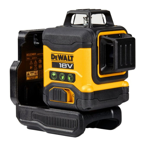
The DCLE34031 3x360 Laser is a Class 2laser product. It is a
self-leveling laser tool that can be used for horizontal (level)
and vertical (plumb) alignmentprojects.
User Safety
Definitions: Safety Guidelines
The definitions below describe the level of severity for each
signal word. Please read the manual and pay attention to
thesesymbols.
DANGER: Indicates an imminently hazardous
situation which, if not avoided, will result in death or
seriousinjury.
WARNING: Indicates a potentially hazardous
situation which, if not avoided, could result in death or
seriousinjury.
CAUTION: Indicates a potentially hazardous
situation which, if not avoided, may result in minor or
moderateinjury.
NOTICE: Indicates a practice not related to
personal injury which, if not avoided, may result in
propertydamage.
If you have any questions or comments about this or any
dewalt tool, go to www.DEWALT.co.kr on theInternet.
WARNING: Never modify the tool or any part of it.
Damage to the laser or personal injury couldresult.
WARNING: Read and understand all instructions.
Failure to follow the warnings and instructions may
result in electric shock, fire and/or seriousinjury.
SAVE THESE INSTRUCTIONS
WARNING: Laser Radiation Exposure. Do not
disassemble or modify the laser level. There are
no user serviceable parts inside. Serious eye injury
couldresult.
WARNING: Hazardous Radiation. Use of controls
or adjustments or performance of procedures other
than those specified herein may result in hazardous
radiationexposure.
CAUTION: Keep fingers clear of the back plate and
stud when mounting with magnets. Fingers may
becomepinched.
CAUTION: Do not stand underneath the laser when
it is mounted with the magnet bracket. Serious
personal injury or damage to the laser may result if the
laserfalls.
The label on your tool may include the followingsymbols.
V.............................volts
mW.......................milliwatts
.........................laser warning symbol
nm........................wavelength in nanometers
2.............................Class 2Laser
Warning Labels
For your convenience and safety, the following labels
are on yourlaser.
WARNING: To reduce the risk of injury, user
must read instructionmanual.
WARNING: LASER RADIATION. DO NOT
STARE INTO BEAM. Class 2LaserProduct.
WARNING: Keep clear of magnet. Magnet
hazard can disturb pacemaker operation
and result in serious injury ordeath.
• If the equipment is used in a manner not specified
by the manufacturer, the protection provided by the
equipment may beimpaired.
• Do not operate the laser in explosive atmospheres,
such as in the presence of flammable liquids, gases,
or dust. Power tools create sparks which may ignite the
dust orfumes.
• Use the laser only with the specifically designated
batteries. Use of any other batteries may create a risk
offire.

ENGLISH
8
• Store idle laser out of reach of children and other
untrained persons. Lasers are dangerous in the hands of
untrainedusers.
• Tool service MUST be performed by qualified repair
personnel. Service or maintenance performed by
unqualified personnel may result in injury. To locate your
nearest DEWALT service centre go to www.DEWALT.co.kr.
• Do not use tool if switch does not turn it on or off. Any
tool that cannot be controlled with the switch is dangerous
and must berepaired.
• Do not use optical tools such as a telescope or transit
to view the laser beam. Serious eye injury couldresult.
• Do not place the laser in a position which may cause
anyone to intentionally or unintentionally stare into
the laser beam. Serious eye injury couldresult.
• Do not position the laser near a reflective surface
which may reflect the laser beam toward anyone’s
eyes. Serious eye injury couldresult.
• Turn the laser off when it is not in use. Leaving the
laser on increases the risk of staring into the laser
beam. Do not modify the laser in any way. Modifying the
tool may result in hazardous laser radiationexposure.
• Do not operate the laser around children or allow
children to operate the laser. Serious eye injury
mayresult.
• Do not remove or deface warning labels. If labels
are removed user or others may inadvertently expose
themselves toradiation.
• Position the laser securely on a level surface. Damage
to the laser or serious injury could result if the laserfalls.
Personal Safety
• Stay alert, watch what you are doing, and use common
sense when operating the laser. Do not use the laser when
you are tired or under the influence of drugs, alcohol, or
medication. A moment of inattention while operating the
laser may result in serious personalinjury.
• Use personal protective equipment. Always wear eye
protection. Depending on the work conditions, wearing
protective equipment such as a dust mask, non-skid
safety shoes, hard hat, and hearing protection will reduce
personalinjury.
Batteries Chargers/Charge Times (Minutes)
Cat # VDC Ah Weight(kg) DCB104 DCB107 DCB112 DCB113 DCB115 DCB116 DCB117 DCB118 DCB132 DCB119
DCB181 18 1.5 0.35 22 70 45 35 22 22 22 22 22 45
DCB182 18 4.0 0.61 60/40** 185 120 100 60 60/45** 60/40** 60/40** 60 120
DCB183/B/G 18 2.0 0.40 30 90 60 50 30 30 30 30 30 60
DCB184/B/G 18 5.0 0.62 75/50** 240 150 120 75 75/60** 75/50** 75/50** 75 150
DCB185 18 1.3 0.35 22 60 40 30 22 22 22 22 22 40
DCB187 18 3.0 0.54 45 140 90 70 45 45 45 45 45 90
DCB189 18 4.0 0.54 60 185 120 100 60 60 60 60 60 120
*Date code 201811475B or later
**Date code 201536 or later
Battery Packs
Important Safety Instructions for All
BatteryPacks
When ordering replacement battery packs, be sure to include
catalogue number andvoltage.
The battery pack is not fully charged out of the carton.
Before using the battery pack and charger, read
the safety instructions below. Then follow charging
proceduresoutlined.
READ ALL INSTRUCTIONS
• Do not charge or use battery in explosive
atmospheres, such as in the presence of flammable
liquids, gases or dust. Inserting or removing the battery
from the charger may ignite the dust orfumes.
• Never force battery pack into charger. Do not modify
battery pack in any way to fit into a non-compatible
charger as battery pack may rupture causing serious
personalinjury.
• Charge the battery packs only in DEWALTchargers.
• DO NOT splash or immerse in water or otherliquids.
• Do not store or use the tool and battery pack in
locations where the temperature may fall below 4˚C
(39.2˚F) (such as outside sheds or metal buildings
in winter), or reach or exceed 40˚C (104˚F) (such as
outside sheds or metal buildings insummer).
• Do not incinerate the battery pack even if it is
severely damaged or is completely worn out. The
battery pack can explode in a fire. Toxic fumes and
materials are created when lithium-ion battery packs
areburned.
• If battery contents come into contact with the skin,
immediately wash area with mild soap and water. If
battery liquid gets into the eye, rinse water over the open
eye for 15minutes or until irritation ceases. If medical
attention is needed, the battery electrolyte is composed of a
mixture of liquid organic carbonates and lithiumsalts.
• Contents of opened battery cells may cause
respiratory irritation. Provide fresh air. If symptoms
persists, seek medicalattention.
9
ENGLISH
WARNING: Burn hazard. Battery liquid may be
flammable if exposed to spark orflame.
WARNING: Never attempt to open the battery pack for
any reason. If battery pack case is cracked or damaged,
do not insert into charger. Do not crush, drop or
damage battery pack. Do not use a battery pack or
charger that has received a sharp blow, been dropped,
run over or damaged in any way (i.e., pierced with a
nail, hit with a hammer, stepped on). Electric shock
or electrocution may result. Damaged battery packs
should be returned to service centre forrecycling.
WARNING: Fire hazard. Do not store or carry the
battery pack so that metal objects can contact
exposed battery terminals. For example, do not
place the battery pack in aprons, pockets, tool boxes,
product kit boxes, drawers, etc., with loose nails, screws,
keys,etc.
CAUTION: When not in use, place tool on its side
on a stable surface where it will not cause a
tripping or falling hazard. Some tools with large
battery packs will stand upright on the battery pack
but may be easily knockedover.
Transportation
WARNING: Fire hazard. Transporting batteries can
possibly cause fire if the battery terminals inadvertently
come in contact with conductive materials. When
transporting batteries, make sure that the battery
terminals are protected and well insulated from
materials that could contact them and cause a short
circuit. NOTE: Lithium-ion batteries should not be put
in checkedbaggage.
DEWALT batteries comply with all applicable shipping
regulations as prescribed by industry and legal standards
which include UN Recommendations on the Transport of
Dangerous Goods; International Air Transport Association
(IATA) Dangerous Goods Regulations, International Maritime
Dangerous Goods (IMDG) Regulations, and the European
Agreement Concerning The International Carriage of
Dangerous Goods by Road (ADR). Lithium-ion cells and
batteries have been tested to section 38.3of the UN
Recommendations on the Transport of Dangerous Goods
Manual of Tests andCriteria.
In most instances, shipping a DEWALT battery pack will be
excepted from being classified as a fully regulated Class
9Hazardous Material. In general, only shipments containing
a lithium-ion battery with an energy rating greater than
100Watt Hours (Wh) will require being shipped as fully
regulated Class 9. All lithium-ion batteries have the Watt
Hour rating marked on the pack. Furthermore, due to
regulation complexities, DEWALT does not recommend air
shipping lithium-ion battery packs alone regardless of Watt
Hour rating. Shipments of tools with batteries (combo kits)
can be air shipped as excepted if the Watt Hour rating of the
battery pack is no greater than 100Wh.
Regardless of whether a shipment is considered excepted
or fully regulated, it is the shipper's responsibility to consult
the latest regulations for packaging, labeling/marking and
documentationrequirements.
The information provided in this section of the manual
is provided in good faith and believed to be accurate
at the time the document was created. However, no
warranty, expressed or implied, is given. It is the buyer’s
responsibility to ensure that its activities comply with the
applicableregulations.
Transporting the FLEXVOLTTM Battery
The DEWALT FLEXVOLTTM battery has two modes: Use
andTransport.
Use Mode: When the FLEXVOLTTM battery stands alone or is
in a DEWALT 20V Max product, it will operate as an 20V Max
battery. When the FLEXVOLTTM battery is in a 54V or a 108V
(two 54V batteries) product, it will operate as a 54Vbattery.
Transport Mode: When the cap is attached to the
FLEXVOLTTM battery, the battery is in Transport mode. Keep
the cap forshipping.
When in Transport mode,
strings of cells are electrically
disconnected within the pack
resulting in 3batteries with a
lower Watt hour (Wh) rating as compared to 1battery with a
higher Watt hour rating. This increased quantity of 3batteries
with the lower Watt hour rating can exempt the pack from
certain shipping regulations that are imposed upon the
higher Watt hour batteries.
For example, the
Transport Wh rating
might indicate
3x36Wh, meaning
3batteries of
36Wh each. The Use Wh rating might indicate 108Wh
(1batteryimplied).
Storage Recommendations
1. The best storage place is one that is cool and dry
away from direct sunlight and excess heat or cold. For
optimum battery performance and life, store battery
packs at room temperature when not inuse.
2. For long storage, it is recommended to store a fully
charged battery pack in a cool, dry place out of the
charger for optimalresults.
NOTE: Battery packs should not be stored completely
depleted of charge. The battery pack will need to be
recharged beforeuse.
Labels on Charger and Battery Pack
In addition to the pictographs used in this manual, the
labels on the charger and the battery pack may show the
followingpictographs:
LRead instruction manual beforeuse.
p See Technical Data for chargingtime.
Example of Use and Transport Label Marking

ENGLISH
10
Chargers
D EWALT chargers require no adjustment and are designed to
be as easy as possible tooperate.
Electrical Safety
The electric motor has been designed for one voltage only.
Always check that the battery pack voltage corresponds
to the voltage on the rating plate. Also make sure that the
voltage of your charger corresponds to that of yourmains.
iYour DEWALT charger is double insulated in
accordance with EN60335; therefore no earth
wire isrequired.
If the supply cord is damaged, it must be replaced only by
D EWALT or an authorised serviceorganisation.
Mains Plug Replacement
(U.K.& Ireland Only)
If a new mains plug needs to be fitted:
• Safely dispose of the oldplug.
• Connect the brown lead to the live terminal in theplug.
• Connect the blue lead to the neutralterminal.
WARNING: No connection is to be made to the
earthterminal.
Follow the fitting instructions supplied with good quality
plugs. Recommended fuse: 3A.
Using an Extension Cable
An extension cord should not be used unless absolutely
necessary. Use an approved extension cable suitable for
the power input of your charger (see Technical Data). The
minimum conductor size is 1mm2; the maximum length
is30m.
When using a cable reel, always unwind the
cablecompletely.
Important Safety Instructions for All
BatteryChargers
SAVE THESE INSTRUCTIONS: This manual contains
important safety and operating instructions for compatible
battery chargers (refer to TechnicalData).
• Before using charger, read all instructions and cautionary
markings on charger, battery pack, and product using
batterypack.
WARNING: Shock hazard. Do not allow any liquid to
get inside charger. Electric shock mayresult.
WARNING: We recommend the use of a residual
current device with a residual current rating of 30mA
orless.
CAUTION: Burn hazard. To reduce the risk of injury,
charge only DEWALT rechargeable batteries. Other
types of batteries may burst causing personal injury
anddamage.
CAUTION: Children should be supervised to ensure
that they do not play with theappliance.
NOTICE: Under certain conditions, with the charger
plugged into the power supply, the exposed charging
contacts inside the charger can be shorted by foreign
material. Foreign materials of a conductive nature
such as, but not limited to, steel wool, aluminum foil or
any buildup of metallic particles should be kept away
from charger cavities. Always unplug the charger from
the power supply when there is no battery pack in the
cavity. Unplug charger before attempting toclean.
• DO NOT attempt to charge the battery pack with
any chargers other than the ones in this manual.
The charger and battery pack are specifically designed to
worktogether.
• These chargers are not intended for any uses other
than charging DEWALT rechargeable batteries.
Any other uses may result in risk of fire, electric shock
orelectrocution.
• Do not expose charger to rain orsnow.
• Pull by plug rather than cord when disconnecting
charger. This will reduce risk ofdamage to electric plug
andcord.
• Make sure that cord is located so that it will not be
stepped on, tripped over, or otherwise subjected to
damage orstress.
• Do not use an extension cord unless it is absolutely
necessary. Use of improper extension cord could result in
risk of fire,electric shock, orelectrocution.
• Do not place any object on top of charger or place
the charger on a soft surface that might block the
q Do not probe with conductiveobjects.
r Do not charge damaged batterypacks.
s Do not expose towater.
t Have defective cords replacedimmediately
u Charge only between 4˚C and 40˚C.
v Only for indooruse.
x Discard the battery pack with due care for
theenvironment.
y Charge DEWALT battery packs only with designated
D EWALT chargers. Charging battery packs other than
the designated DEWALT batteries with a DEWALT
charger may make them burst or lead to other
dangeroussituations.
z Do not incinerate the batterypack.
B USE (without transport cap). Example: Wh rating
indicates 108Wh (1battery with 108Wh).
A TRANSPORT (with built-in transport cap). Example:
Wh rating indicates 3x 36Wh (3batteries of 36Wh).

11
ENGLISH
ventilation slots and result in excessive internal heat.
Place the charger in a position away from any heat source.
The charger is ventilated through slots in the top and the
bottom of thehousing.
• Do not operate charger with damaged cord or plug—
have them replacedimmediately.
• Do not operate charger if it has received a sharp
blow, been dropped, or otherwise damaged in any
way. Take it to an authorised servicecentre.
• Do not disassemble charger; take it to an authorised
service centre when service or repair is required.
Incorrect reassembly may result in a risk of electric shock,
electrocution orfire.
• In case of damaged power supply cord, the supply cord
must be replaced immediately by the manufacturer,
its service agent or similar qualified person to prevent
anyhazard.
• Disconnect the charger from the outlet before
attempting any cleaning. This will reduce the risk of
electric shock. Removing the battery pack will not reduce
thisrisk.
• NEVER attempt to connect two chargerstogether.
• The charger is designed to operate on standard
230V household electrical power. Do not attempt to
use it on any other voltage. This does not apply to the
vehicularcharger.
Charging a Battery (Fig.B)
1. Plug the charger into an appropriate outlet before
inserting batterypack.
2. Insert the battery pack 1 into the charger, making sure
the battery pack is fully seated in the charger. The red
(charging) light will blink repeatedly indicating that the
charging process hasstarted.
3. The completion of charge will be indicated by the red
light remaining ON continuously. The battery pack is
fully charged and may be used at this time or left in the
charger. To remove the battery pack from the charger,
push the battery release button 7 on the batterypack.
NOTE: To ensure maximum performance and life of
lithium-ion battery packs, charge the battery pack fully
before firstuse.
Charger Operation
Refer to the indicators below for the charge status of the
batterypack.
Charge Indicators
FCharging I
GFully Charged J
HHot/Cold Pack Delay* K
*The red light will continue to blink, but a yellow indicator
light will be illuminated during this operation. Once the
battery pack has reached an appropriate temperature, the
yellow light will turn off and the charger will resume the
chargingprocedure.
The compatible charger(s) will not charge a faulty battery
pack. The charger will indicate faulty battery by refusing
tolight.
NOTE: This could also mean a problem with acharger.
If the charger indicates a problem, take the charger and
battery pack to be tested at an authorised servicecentre.
Hot/Cold Pack Delay
When the charger detects a battery pack that is too hot
or too cold, it automatically starts a Hot/Cold Pack Delay,
suspending charging until the battery pack has reached an
appropriate temperature. The charger then automatically
switches to the pack charging mode. This feature ensures
maximum battery packlife.
A cold battery pack will charge at a slower rate than a warm
battery pack. The battery pack will charge at that slower rate
throughout the entire charging cycle and will not return to
maximum charge rate even if the battery packwarms.
The DCB118 charger is equipped with an internal fan
designed to cool the battery pack. The fan will turn on
automatically when the battery pack needs to be cooled.
Never operate the charger if the fan does not operate
properly or if ventilation slots are blocked. Do not permit
foreign objects to enter the interior of thecharger.
Electronic Protection System
XR Li-Ion tools are designed with an Electronic Protection
System that will protect the battery pack against overloading,
overheating or deepdischarge.
The tool will automatically turn off if the Electronic Protection
System engages. If this occurs, place the lithium-ion battery
pack on the charger until it is fullycharged.
Wall Mounting
These chargers are designed to be wall mountable or to sit
upright on a table or work surface. If wall mounting, locate
the charger within reach of an electrical outlet, and away
from a corner or other obstructions which may impede
air flow. Use the back of the charger as a template for the
location of the mounting screws on the wall. Mount the
charger securely using drywall screws (purchased separately)
at least 25.4mm long with a screw head diameter of
7–9mm, screwed into wood to an optimal depth leaving
approximately 5.5mm of the screw exposed. Align the slots
on the back of the charger with the exposed screws and fully
engage them in theslots.
Charger Cleaning Instructions
WARNING: Shock hazard. Disconnect the charger
from the AC outlet before cleaning. Dirt and grease
may be removed from the exterior of the charger using
a cloth or soft non-metallic brush. Do not use water
or any cleaning solutions. Never let any liquid get
inside the tool; never immerse any part of the tool into
aliquid.

ENGLISH
12
Inserting and Removing the Battery Pack
from the Tool (Fig. B)
NOTE: Make sure your battery pack 1 is fullycharged.
To Install the Battery Pack into the Tool
Handle
1. Align the battery pack 1 with the rails inside the tool’s
handle (Fig. B).
2. Slide it into the handle until the battery pack is firmly
seated in the tool and ensure that you hear the lock snap
intoplace.
To Remove the Battery Pack from the Tool
1. Press the battery release button 7 and firmly pull the
battery pack out of the toolhandle.
2. Insert battery pack into the charger as described in the
charger section of thismanual.
Fuel Gauge Battery Packs (Fig.B)
Some DEWALT battery packs include a fuel gauge which
consists of three green LED lights that indicate the level of
charge remaining in the batterypack.
To actuate the fuel gauge, press and hold the fuel gauge
button8. A combination of the three green LED lights will
illuminate designating the level of charge left. When the
level of charge in the battery is below the usable limit, the
fuel gauge will not illuminate and the battery will need to
berecharged.
NOTE: The fuel gauge is only an indication of the charge left
on the battery pack. It does not indicate tool functionality
and is subject to variation based on product components,
temperature and end-userapplication.
POWERING THE LASER
OPERATING TIPS
• To extend battery life per charge, turn the laser off when
it is not inuse.
• To ensure the accuracy of your work, check the laser
calibration often. Refer to Checking LaserAccuracy.
• Before attempting to use the laser, make sure it is
positioned securely, on a smooth, flat stable surface that
is level in bothdirections.
• To increase beam visibility, use a Laser Target Card
(FigureT).
CAUTION: To reduce the risk of serious injury,
never stare directly into the laser beam with or
without these glasses. Refer to Accessories for
importantinformation.
• Always mark the centre of the beam created by thelaser.
• Extreme temperature changes can cause movement or
shifting of building structures, metal tripods, equipment,
etc., which can effect accuracy. Check your accuracy
often whileworking.
• If the laser has been dropped, check to make sure your
laser is still calibrated. Refer to Checking LaserAccuracy.
TURNING THE LASER ON (FIG. A)
Place the laser on a flat level surface. Slide the Power/
Transport Lock switch2 to the right to unlock/turn ON
thelaser.
Each laser line is powered on by pressing its buttonon the
keypad3. Pressing the button again turns the laser line off.
The laser lines can be powered one at a time or all at the
sametime.
Button Displays
Horizontal laser line4
Side vertical laser line5
Front vertical laser line6
When the laser is not in use, slide the Power/Transport Lock
switch to the left in the OFF/Lockedposition.
CHECKING LASER ACCURACY
The laser tools are sealed and calibrated at the factory.
It is recommended that you perform an accuracy check
prior to using the laser for the first time (in case the laser
was exposed to extreme temperatures) and then regularly
to ensure the accuracy of your work. When performing
any of the accuracy checks listed in this manual, follow
theseguidelines:
• Use the largest area/distance possible, closest to the
operating distance. The greater the area/distance, the
easier to measure the accuracy of thelaser.
• Place the laser on asmooth, flat, stable surface that is
level in bothdirections.
• Mark the centre of the laserbeam.
FIELD CALIBRATION CHECK
Horizontal Beam - Scan Direction
(Fig. A, F, G, H)
Checking the horizontal pitch calibration of the laser requires
a single wall at least 30’ (9 m) long. It is important to conduct
a calibration check using a distance no shorter than the
distance of the applications for which the tool will beused.
1. Place the laser against the end of the wall on a smooth,
flat, stable surface that is level in both directions
(FigureF).
2. Move the Power/Transport Lock switch2 to the right to
turn the laser ON (FigureA).
3. Press the button to turn on the horizontal beam4.
4. At least 30' (9m) apart along the laser beam, marka
andb.
5. Turn the laser180º.
6. Adjust the height of the laser so the centre of the beam is
aligned witha (FigureG).
7. Directly above or belowb, markc along the laser beam
(FigureH).
8. Measure the vertical distance betweenb andc .

13
ENGLISH
9. If your measurement is greater than the Allowable
Distance Betweenb andc for the corresponding
Distance Between Walls in the following table, the laser
must be serviced at an authorised servicecentre.
Distance Between aand bAllowable Distance Between
band c
10.0 m 6.0 mm
12.0 m 7.2 mm
15.0 m 9.0 mm
Horizontal Beam - Pitch Direction
(Fig. A, I, J, K)
Checking the horizontal pitch calibration of the laser requires
a single wall at least 30’ (9 m) long. It is important to conduct
a calibration check using a distance no shorter than the
distance of the applications for which the tool will beused.
1. Place the laser against the end of the wall on a smooth,
flat, stable surface that is level in both directions
(FigureI).
2. Move the Power/Transport Lock switch2 to the right to
turn the laser ON (FigureA).
3. Press button to turn on the horizontal beam4.
4. At least 30' (9m) apart along the laser beam, marka
andb.
5. Move the laser to the opposite end of the wall (FigureJ).
6. Position the laser toward the first end of the same wall
and parallel to the adjacentwall.
7. Adjust the height of the laser so the centre of the beam is
aligned withb.
8. Directly above or belowa, markc along the laser beam
(FigureK).
9. Measure the distance betweena andc.
10. If your measurement is greater than the Allowable
Distance Between a andc for the corresponding
Distance Between Walls in the following table, the laser
must be serviced at an authorised servicecentre.
Distance Between aand bAllowable Distance Between
aand c
10.0 m 6.0 mm
12.0 m 7.2 mm
15.0 m 9.0 mm
Vertical Beam (Fig. L)
Checking the vertical (plumb) calibration of the laser can be
most accurately done when there is a substantial amount of
vertical height available, ideally 20’ (6m), with one person
on the floor positioning the laser and another person near
a ceiling to mark the position of the beam. It is important
to conduct a calibration check using a distance no shorter
than the distance of the applications for which the tool will
beused.
1. Place the laser on a smooth, flat, stable surface that is
level in both directions (Figure L1).
2. Move the Power/Transport Lock switch2 to the right to
turn the laser ON (FigureA).
3. Press the buttons to turn on both vertical beams56.
4. Mark two short lines where the beams cross a,b and
also on the ceilingc,d. Always mark the centre of the
beam’s thickness (Figure L2).
5. Pick up and rotate the laser 180º, and position it so
the beams line up with the marked lines on the level
surfacee, f(Figure L3).
6. Mark two short lines where the beams cross on the
ceilingg,h.
7. Measure the distance between each set of marked lines
on the ceiling ( c,g andd,h). If the measurement is
greater than the values shown below, the laser must be
serviced at an authorised servicecentre.
Ceiling Height Allowable Distance Between
Marks
2.5 m 1.7 mm
3.0 m 2.1 mm
4.0 m 2.8 mm
6.0 m 4.1 mm
9.0 m 6.2 mm
90º Accuracy Between Vertical Beams
(Fig. M)
Checking 90º accuracy requires an open floor area at least 33’
x 18’ (10mm x 5mm). Refer to Figure M for the position of
the laser at each step and for the location of the marks made
at each step. Always mark the centre of the beam’s thickness.
Place the laser on a smooth, flat, stable surface that is level in
bothdirections.
1. Move the Power/Transport Lock switch2 to the right to
turn the laser ON (FigureA).
2. Press button to turn on the side vertical beam6.
3. Mark the centre of the beam at three locations
(a,b,c) on the floor along the side laser line. Markb
should be at the midpoint of the laser line (Figure M1).
4. Pick up and move the laser tob.
5. Press6 to turn on the front vertical beam too
(Figure M2).
6. Position the front vertical beam so it crosses precisely
atb, with the side beam aligned withc (Figure M2).
7. Mark a locatione along the front vertical beam at least
14’ (4m) away from the unit (Figure M2).
8. Rotate the laser 90º so the side vertical beam now passes
throughb ande (Figure M3).
9. Directly above or belowa, mark falong the front
verticalbeam.
10. Measure the distance betweena and fIf the
measurement is greater than the values shown
below, the laser must be serviced at an authorised
servicecentre.
Distance from
ato b
Allowable Distance Between
aand f
4.0 m 3.5 mm
5.0 m 4.4 mm
6.0 m 5.3 mm
7.0 m 6.2 mm
f

ENGLISH
14
USING THE LASER
Leveling the Laser
As long as the laser is properly calibrated, the laser is
self-leveling. Each laser is calibrated at the factory to find
level as long as it is positioned on a flat surface within
average ± 4° of level. No manual adjustments arerequired.
If the laser has been tilted so much that it cannot self-level (>
4°), the laser beam will flash.
When the beams flash as noted above THE LASER IS
NOT LEVEL (OR PLUMB) AND SHOULD NOT BE USED
FOR DETERMINING OR MARKING LEVEL OR PLUMB.
Tryrepositioning the laser on a more levelsurface.
Using the Pivot Bracket (Fig. N, O, P)
The laser has a magnetic pivot bracket (Figure N,9)
permanently attached to theunit.
WARNING: Position the laser and/or wall mount on
astable surface. Serious personal injury or damage to
the laser may result if the laserfalls.
• The bracket has a keyhole slot (Figure O10) so it can be
hung from a nail or screw on any kind ofsurface.
• The bracket has magnets (Figure P) which allow the unit
to be mounted to most upright surfaces made of steel
or iron. Common examples of suitable surfaces include
steel framing studs, steel door frames, and structural
steel beams. Before attaching the pivot bracket against a
stud (Figure P11), place the Metal Enhancement Plate
(FigureP12) on the opposite side of thestud.
MAINTENANCE
• To maintain the accuracy of your work, check the laser
often to make sure it is properly calibrated. See Field
CalibrationCheck.
• Calibration checks and other maintenance repairs may
be performed by DEWALT service centres.
• Do not store your laser in the kit box if the laser is wet.
The laser should be dried first with a soft dry cloth prior
tostorage.
• Cleaning: Exterior plastic parts may be cleaned with a
damp cloth. Although these parts are solvent resistant,
NEVER use solvents. Use a soft, dry cloth to remove
moisture from the tool beforestorage.
TROUBLESHOOTING
The Laser Does Not Turn On
• Fully-charge the battery pack and then reinstall it in the
laserunit.
• If the laser unit is exposed to extremely hot temperatures,
the unit will not turn on. If the laser has been stored in
extremely hot temperatures, allow it to cool. The laser
level will not be damaged by pressing the on/off button
before cooling to its proper operatingtemperature.
The Laser Beams Flash
The lasers are designed to self-level up to an average of
4° in all directions If the laser is tilted so much that the
internal mechanism cannot level itself, the laser beams will
flash indicating that the tilt range has been exceeded. THE
FLASHING BEAMS CREATED BY THE LASER ARE NOT LEVEL OR
PLUMB AND SHOULD NOT BE USED FOR DETERMINING OR
MARKING LEVEL OR PLUMB. Try repositioning the laser on a
more level surface.
If the laser battery pack has a low state of charge, the
beams will flash in a distinctive pattern of 3quick flashes in
1second, followed by constant light output for 4seconds.
This flashing pattern indicates that the battery pack should
be replaced with a fully charged batterypack.
The Laser Beams Will Not Stop Moving
The laser is a precision instrument. Therefore, if it is not
positioned on a stable (and motionless) surface, the laser
will continue to try to find level. If the beam will not stop
moving, try placing the laser on a more stable surface. Also,
try to make sure that the surface is relatively flat, so that the
laser isstable.
ACCESSORIES (FIG. Q, R, S)
The laser is packaged with a drop ceiling bracket13. The
drop ceiling bracket contains a steel plate and attaches to
the magnetized pivot bracket9 (Figure Q).
The drop ceiling bracket is equipped with both 1/4 - 20and
5/8 - 11female threads on the bottom of the unit).
This thread on is to accommodate current or future DEWALT
accessories. Refer to Figures R and S for examples of
accessories sold seperately. Only use DEWALT accessories
specified for use with this product. Follow the directions
included with the accessory.
WARNING: Since accessories, other than those offered
by DEWALT, have not been tested with this product, use
of such accessories with this tool could be hazardous.
To reduce the risk of injury, only DEWALT recommended
accessories should be used with thisproduct.
If you need any assistance in locating any accessory, please
contact your nearest DEWALT service centre or go to
www.2helpU.com.
Target Card (Fig. T)
Some laser kits include a Laser Target Card (FigureT) to aid
in locating and marking the laser beam. The target card
enhances the visibility of the laser beam as the beam crosses
over the card. The card is marked with standard and metric
scales. The laser beam passes through the semi-transparent
plastic and reflects off of the reflective tape on the reverse
side. The magnet at the top of the card is designed to hold
the target card to ceiling track or steel studs to determine
plumb and level positions. For best performance when using
the Target Card, the DEWALT logo should be facingyou.

15
ENGLISH
Specifications
DCLE34031
Light Source Laser diodes
Laser Wavelength 510 – 530 nm visible
Laser Power ≤1.50 mW (each beam) CLASS 2 LASER PRODUCT
Working Range 40 m
100 m with detector
Accuracy (Plumb) ±3.1 mm per 9 mm
Accuracy (Level) ±3.0 mm per 10 mm
Battery Low Laser beams flash with 3 quick pulses
Continuous Flashing
Laser Beams
Tilt range exceeded/unit is not level
Environmental Water & Dust Resistant to IP54. Applies to product, not battery or charger.
Service and Repairs
NOTE: Disassembling the laser level(s) will void all warranties
on theproduct.
To assure product SAFETY and RELIABILITY, repairs, maintenance
and adjustment should be performed by authorised service
centres. Service or maintenance performed by unqualified
personnel may result in a risk of injury. To locate your nearest
DEWALT service centre go to www.DEWALT.co.kr.
Warranty
Go to www.DEWALT.co.kr for the latest
warrantyinformation.

영어
16
목차
• 레이저 정보
• 사용자 안전 사항
• 배터리 안전 사항
• 레이저 전원 공급
• 사용 팁
• 레이저 켜기
• 레이저 정밀도 확인
• 현장 교정 확인
• 레이저 사용
• 유지관리
• 문제 해결
• 액세서리
• 서비스 및 수리
• 보증
• 규격
레이저 정보
DCLE34031 3x360 레이저는 클래스 2 레이저
제품입니다. 이는 자체 수평 레이저 공구로 수평
(수평) 및 수직(연직) 정렬 프로젝트에 사용할 수
있습니다.
사용자 안전 사항
정의: 안전 지침
아래의 정의는 각 기호어의 심각도 수준을 설명한
것입니다. 설명서를 읽으면서 이런 기호에 주의를
기울이십시오.
위험: 예방하지 않으면 사망 또는 심각한
부상을 초래하는 긴급한 위험 상황을
나타냅니다.
경고: 예방하지 않으면 사망 또는 심각한
부상을 초래할 수 있는 잠재적 위험 상황을
나타냅니다.
주의: 예방하지 않으면 경미하거나 보통의
부상을 초래할 수 있는 잠재적 위험 상황을
나타냅니다.
고지: 개인 부상과는 관련이 없지만,
예방하지 않으면 재산 피해를 초래할 수
있는 실무를 나타냅니다.
이 제품 또는 DEWALT 공구와
관련하여 질문이나 의견이 있는 경우,
인터넷에서 www.DEWALT.co.kr을 방문하여
주십시오.
경고: 절대로 공구의 일부 또는 전체를
개조하지 마십시오. 레이저 손상이나 개인
부상이 발생할 수 있습니다.
경고: 모든 지침을 읽고 이해하십시오.
경고와 지침을 따르지 않으면 감전, 화재 및/
또는 심각한 부상을 초래할 수 있습니다.
이 설명서를 보관하십시오
경고: 레이저 광선 노출. 레이저 레벨기를
분해하거나 개조하지 마십시오. 사용자가
수리할 수 있는 부품이 내부에 없습니다.
심각한 눈 부상을 초래할 수 있습니다.
경고: 위험한 광선 방출. 여기에 명시되지
않은 제어 또는 조정을 사용하거나
절차를 수행하면 위험한 광선에 노출될 수
있습니다.
주의: 자석으로 장착할 때 손가락을 뒷면
플레이트와 스터드에서 멀리 두십시오.
손가락이 끼일 수 있습니다.
주의: 레이저가 자석 브래킷으로 장착되어
있는 경우 레이저 아래에 서 있지 마십시오.
레이저가 떨어지면 심각한 부상 또는
레이저 손상을 유발할 수 있습니다.
공의 라벨은 다음 기호를 포함할 수 있습니다.
V.............................볼트
mW.......................밀리와트
.........................레이저 경고 기호
nm........................나노미터 단위의 파장
2.............................클래스 2 레이저
경고 라벨
사용자 편의와 안전을 위해 다음 라벨이 레이저에
있습니다.
경고: 부상 위험을 줄이려면
사용자는 사용 설명서를 반드시
읽어야 합니다.
경고: 레이저 복사. 빔을 바라보지
마십시오. 클래스 2 레이저 제품.
경고: 자석에서 멀리
떨어지십시오. 자석이 심박
조율기 작동을 방해하여 심각한
부상 또는 사망을 초래할 수
있습니다.
• 제조사가 명시하지 않은 방식으로 장비를
사용하는 경우, 장비에 제공된 보호 기능이
올바르게 작용하지 않을 수 있습니다.
• 인화성 액체, 가스 또는 분진 등이 있는 폭발성
환경에서는 레이저를 작동하지 마십시오.

영어
17
전력 공구가 불꽃을 일으켜 분진 또는 연기를
발화시킬 수 있습니다.
• 특별히 지정된 배터리만 레이저에
사용하십시오. 기타 다른 배터리 팩을 사용하면
화재가 발생할 수 있습니다.
• 사용하지 않는 레이저는 어린이 및 기타
미숙한 사람의 손에 닿지 않게 하십시오.
미숙한 사용자가 레이저를 다루면 위험합니다.
• 공구 서비스는 자격을 갖춘 수리 직원이
수행해야 합니다. 자격이 없는 직원이 서비스
또는 유지관리를 수행하면 부상을 입을 수
있습니다. 가장 가까운 DEWALT 서비스 센터를
찾으려면 www.DEWALT.co.kr을 참조하십시오.
• 스위치로 전원을 켜거나 끌 수 없으면 공구를
사용하지 마십시오. 스위치로 제어할 수 없는
공구는 위험하기 때문에 수리해야 합니다.
• 레이저 빔을 보기 위해 망원경 또는 트랜싯
등의 광학 도구를 사용하지 마십시오. 심각한
눈 부상을 초래할 수 있습니다.
• 누군가 의도적으로 또는 본의 아니게 레이저
빔을 응시할 수 있는 장소에 레이저를
배치하지 마십시오. 심각한 눈 부상을 초래할
수 있습니다.
• 레이저 빔이 누군가의 눈으로 반사될 수
있으니 레이저를 반사면 근처에 배치하지
마십시오. 심각한 눈 부상을 초래할 수
있습니다.
• 사용하지 않을 때는 레이저를 끄십시오.
레이저를 켜두면 레이저 빔을 우발적으로
응시할 가능성이 높아집니다. 절대로 레이저를
개조하지 마십시오. 공구를 개조하면 위험한
레이저 광선에 노출될 수 있습니다.
• 어린이 주변에서 레이저를 작동하지 말고
어린이가 레이저를 조작하도록 두지 마십시오.
심각한 눈 부상을 초래할 수 있습니다.
• 경고 라벨을 제거하거나 훼손하지 마십시오.
라벨이 없으면 사용자 또는 다른 사람들이
광선에 우발적으로 노출될 수 있습니다.
배터리 충전기/충전 시간(분)
카탈로그 번호V
DC Ah 무게 (kg)
DCB104DCB107 DCB112 DCB113 DCB115 DCB116 DCB117 DCB118 DCB132 DCB119
DCB181 18 1.5 0.35 22 70 45 35 22 22 22 22 22 45
DCB182 18 4.0 0.61
60/40**
185 120 100 60
60/45**60/40**60/40**
60 120
DCB183/
B/G 18 2.0 0.40 30 90 60 50 30 30 30 30 30 60
DCB184/
B/G 18 5.0 0.62
75/50**
240 150 120 75
75/60**75/50**75/50**
75 150
DCB185 18 1.3 0.35 22 60 40 30 22 22 22 22 22 40
DCB187 18 3.0 0.54 45 140 90 70 45 45 45 45 45 90
DCB189 18 4.0 0.54 60 185 120 100 60 60 60 60 60 120
*날짜 코드 201811475B 이후
**날짜 코드 201536 이후 ** DCLE34031 레벨기는 FLEX-VOLT 배터리와 호환되지 않습니다. 20V MAX 배터리만 장착
가능합니다.
• 레이저를 평평한 표면 위에 안전하게
배치하십시오. 레이저가 떨어지면 레이저
손상이나 심각한 부상이 발생할 수 있습니다.
개인 안전
• 레이저를 작동할 때는 주의를 집중하고
작업을 주시하며 일반 상식을 활용하십시오.
피곤하거나 약물, 알코올 또는 의약품 등의
영향을 받는 경우 레이저를 사용하지 마십시오.
레이저를 작동하는 동안 부주의하게 작업하면
심각한 부상을 초래할 수 있습니다.
• 개인 보호 장비를 사용하십시오. 항상 보안경을
착용하십시오. 작업 조건에 따라 방진 마스크,
미끄럼 방지 안전화, 안전모, 청각 보호대 등의
보호 장비를 착용하면 개인 부상을 방지할 수
있습니다.
배터리 팩
모든 배터리 팩에 적용되는 중요 안전 지침
교체용 배터리 팩을 주문하는 경우, 카탈로그
번호와 전압을 반드시 포함시켜 주십시오.
포장 상자에서 꺼낸 배터리 팩은 완전히 충전된
상태가 아닙니다. 배터리 팩과 충전기를 사용하기
전에 아래의 안전 지침을 읽어 주십시오. 그 다음,
충전 절차 설명을 따르십시오.
모든 지침 읽기
• 인화성 액체, 가스 또는 분진 등이 있는 폭발성
환경에서는 배터리를 충전하거나 사용하지
마십시오. 배터리를 충전기에 끼우거나 뺄 때
분진이나 연기에 점화가 일어날 수 있습니다.
• 절대로 배터리 팩을 충전기에 강제로 끼우지
마십시오. 호환되지 않는 충전기에 배터리
팩을 끼우려고 개조하면 배터리 팩이 파열되어
심각한 부상을 초래할 수 있으니 절대로
개조하지 마십시오.
• 오직 DEWALT 충전기로만 배터리 팩을
충전하십시오.
• 절대로 물 또는 기타 액체에 적시거나 담그지
마십시오.

영어
18
• 온도가 4˚C(39.2˚F) 미만으로 떨어질 수 있는
장소(예: 겨울철 실외 창고 또는 금속재 건물)
또는 40˚C(104˚F) 이상으로 올라갈 수 있는
장소(예: 여름철 실외 창고 또는 금속재 건물)
에 공구와 배터리 팩을 보관하거나 사용하지
마십시오.
• 직사광선이 비치는 차량 내부에는 제품 또는
배터리를 보관하지 마십시오.
• 배터리 팩이 심각하게 손상되거나 완전히 낡은
경우라도 배터리 팩을 소각하지 마십시오.
배터리 팩이 화염 속에서 폭발할 수 있습니다.
리튬 이온 배터리를 태우면 유독성 연기와
물질이 생성될 수 있습니다.
• 배터리 내용물이 피부에 닿은 경우, 즉시
연성 비누와 물로 해당 부위를 씻으십시오.
배터리액이 눈에 들어간 경우, 눈을 뜬
상태에서 15분 동안 또는 자극이 멈출 때까지
물로 헹구십시오. 의사의 진료가 필요한 경우,
배터리 전해액이 액체 상태의 유기 탄산염과
리튬염 혼합물로 구성되어 있음을 알리십시오.
• 개봉된 배터리 셀의 내용물이 호흡기
자극을 유발할 수 있습니다. 신선한 공기를
제공하십시오. 증상이 지속되면 의사의 진료를
받으십시오.
경고: 화상 위험. 배터리액이 불꽃이나
화염에 노출되면 발화할 수 있습니다.
경고: 어떤 이유로든 절대로 배터리
팩을 개봉하려고 하지 마십시오. 배터리
팩 케이스가 갈라졌거나 손상되었으면
충전기에 끼우지 마십시오. 배터리 팩을
압착하거나 떨어뜨리거나 손상시키지
마십시오. 배터리 팩 또는 충전기가
날카로운 것에 찔리거나 떨어지거나
밟히거나 어떤 식으로든 손상된 경우
사용하지 마십시오(예를 들어, 못에
찔리거나 망치로 두들기거나 밟고 올라선
경우). 전기 충격 또는 감전사가 발생할 수
있습니다. 손상된 배터리 팩은 재활용을
위해 서비스 센터로 반송해야 합니다.
경고: 화재 위험. 노출된 배터리 단자에
금속 물체가 닿을 수 있는 상황에서 배터리
팩을 보관하거나 휴대하지 마십시오. 예를
들어 빠진 못, 나사, 열쇠 등이 있는 앞치마,
주머니, 공구 상자, 제품 키트 상자, 서랍
등에 배터리 팩을 두지 마십시오.
주의: 공구를 사용하지 않을 때는 걸리거나
떨어질 위험이 없는 평면에 옆으로 눕혀서
두십시오. 대형 배터리 팩이 장착된 일부
공구는 배터리 팩 위에 똑바로 세워지지만
쉽게 넘어질 수 있습니다.
운송 경고: 화재 위험. 배터리를 운송할 때 배터리
단자가 전도성 물체와 우발적으로 접촉하면
화재가 발생할 수 있습니다. 배터리를
운송할 때 배터리 단자가 다른 물체와
접촉하여 단락이 발생하지 않도록 배터리
단자를 보호하고 적절하게 절연시키십시오.
참고: 리튬 이온 배터리는 위탁 수하물에
넣으면 안 됩니다.
DEWALT 배터리는 위험물 운송에 관한 UN 권장
사항, 국제 항공 운송 협회(IATA) 위험물 규정,
국제 해상 위험물(IMDG) 규정 및 국제 위험물 도로
운송(ADR)에 관한 유럽 협약을 비롯하여 산업
및 법적 표준에서 기술한 모든 해당 운송 규정을
준수합니다. 리튬 이온 전지 및 배터리는 테스트 및
기준에 관한 위험물 운송 매뉴얼의 UN 권장사항
섹션 38.3에 따라 테스트를 받았습니다.
대부분의 경우 DEWALT 배터리 팩의 운송은
완전히 규제되는 클래스 9 위험 물질로 분류되는
것에서 제외됩니다. 일반적으로 에너지 등급이
100 와트시(Wh)를 초과하는 리튬 이온 배터리가
포함된 운송만 완전히 규제된 클래스 9로
운송되어야 합니다. 모든 리튬 이온 배터리는
팩에 와트시 등급이 표시되어 있습니다. 또한
규제의 복잡성으로 인해 DEWALT 는 와트시 등급에
관계없이 리튬 이온 배터리 팩을 단독으로 항공
운송하는 것을 권장하지 않습니다. 배터리가
포함된 공구(콤보 키트)를 운송할 때 배터리
팩의 와트시 정격이 100 Wh 이하인 경우에는
예외적으로 항공 운송이 가능합니다.
운송이 제외되거나 완전히 규제된 것으로
간주되는지 여부에 상관없이 운송업체는 포장,
라벨/표시 및 서류 요건과 관련하여 최근 규정을
참조해야 합니다.
본 설명서의 이 섹션에서 제시하는 정보는
옳은 의도로 제공된 것이며 문서 작성 당시
정확한 것으로 간주됩니다. 하지만 명시적이든
묵시적이든 어떤 보증도 확립하는 것이 아닙니다.
구매자는 본인의 작업 활동이 해당 규정을
준수하는지 확인해야 합니다.
보관 권장사항
1. 최상의 보관 장소는 서늘하고 건조하며,
직사광선과 과도한 열 또는 냉기로부터 떨어진
곳입니다. 최적의 배터리 성능과 수명을 위해
사용하지 않을 때는 배터리 팩을 실온에
보관하십시오.
2. 장기간 보관할 경우 최적 결과를 유지하려면
완전히 충전된 배터리 팩을 충전기에서 꺼내서,
서늘하고 건조한 장소에 보관하는 것이
좋습니다.
참고: 배터리 팩을 완전히 방전된 상태로
보관해서는 안 됩니다. 배터리 팩을 사용하기 전에
충전해야 합니다.
충전기 및 배터리 팩의 라벨
이 설명서에 사용된 그림 문자 외에도 충전기 및
배터리 팩의 라벨에는 다음 그림 문자가 표시될 수
있습니다.
L사용 전에 사용 설명서를 읽어 주십시오.
p 충전 시간은 기술 데이터를 참조하십시오.
Other manuals for DCLE34031
3
Table of contents
Languages:
Other DeWalt Laser Level manuals

DeWalt
DeWalt DW073 User manual

DeWalt
DeWalt DW060 User manual

DeWalt
DeWalt DW08802 User manual

DeWalt
DeWalt DCE074R User manual

DeWalt
DeWalt DW071 User manual

DeWalt
DeWalt LASERCHALKLINE DW086-XE User manual

DeWalt
DeWalt DCLE34220 User manual

DeWalt
DeWalt DCLE34031 User manual

DeWalt
DeWalt DW076 User manual

DeWalt
DeWalt DW079LR User manual

DeWalt
DeWalt DW074 User manual

DeWalt
DeWalt DW089LR User manual

DeWalt
DeWalt DW079 User manual

DeWalt
DeWalt DW088K Guide

DeWalt
DeWalt DW08301 User manual

DeWalt
DeWalt DW087K User manual

DeWalt
DeWalt DW084 User manual

DeWalt
DeWalt DCE0825R User manual

DeWalt
DeWalt DW0732 User manual

DeWalt
DeWalt DW089-XE User manual