manuals.online logo
Brands
  1. Home
  2. •
  3. Brands
  4. •
  5. DeWalt
  6. •
  7. Laser Level
  8. •
  9. DeWalt DW079LR T2 Series User manual

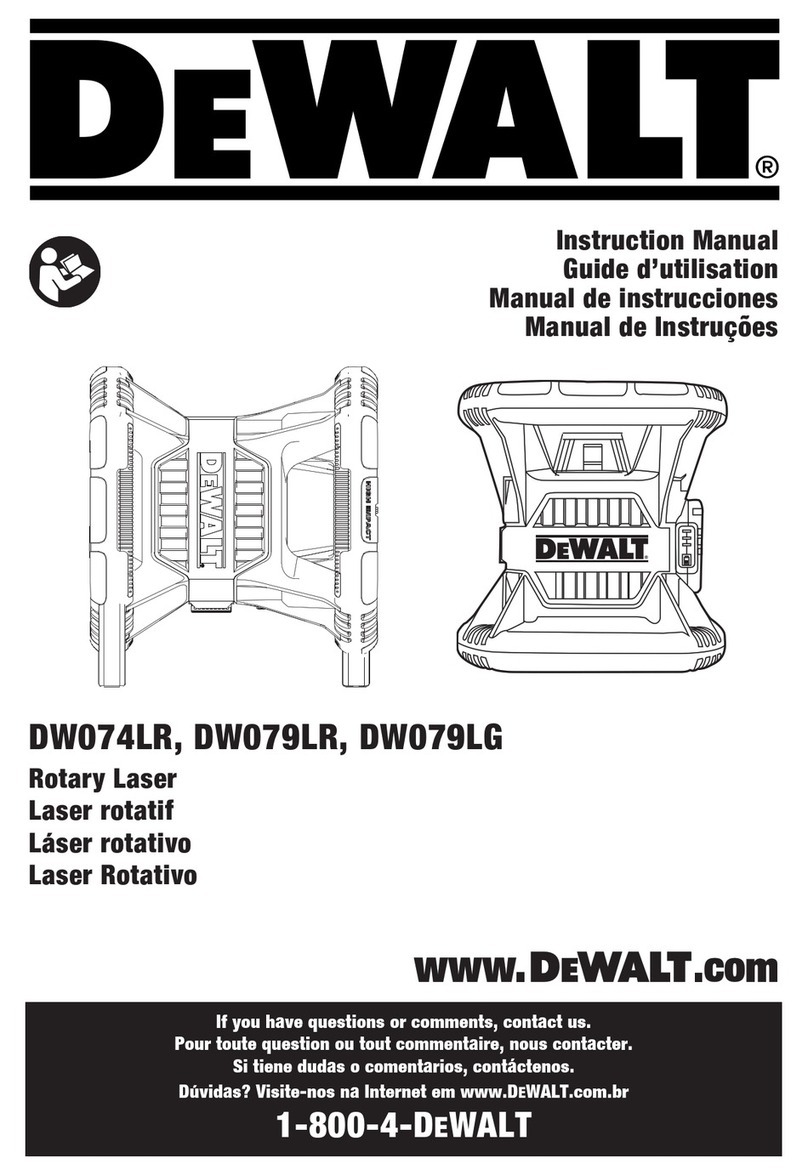
DeWalt DW079LR T2 Series User manual

This manual suits for next models

3

Other DeWalt Laser Level manuals

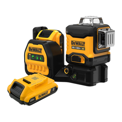
DeWalt DCLE34031 User manual

DeWalt

DeWalt DCLE34031 User manual

DeWalt DCE089D1G18 User manual

DeWalt

DeWalt DCE089D1G18 User manual

DeWalt DCLE34031 User manual

DeWalt

DeWalt DCLE34031 User manual

DeWalt DWHT77100-XJ User manual

DeWalt

DeWalt DWHT77100-XJ User manual

DeWalt DCLE34030 User manual

DeWalt

DeWalt DCLE34030 User manual

DeWalt DCLE34031 User manual

DeWalt

DeWalt DCLE34031 User manual

DeWalt DW088K Guide

DeWalt

DeWalt DW088K Guide

DeWalt DW083 User manual

DeWalt

DeWalt DW083 User manual

DeWalt LaserChalkLine DCE088G User manual

DeWalt

DeWalt LaserChalkLine DCE088G User manual

DeWalt DW099E User manual

DeWalt

DeWalt DW099E User manual

DeWalt DW08802 User manual

DeWalt

DeWalt DW08802 User manual

DeWalt DW071 User manual

DeWalt

DeWalt DW071 User manual

DeWalt DW060 User manual

DeWalt

DeWalt DW060 User manual

DeWalt DW073 User manual

DeWalt

DeWalt DW073 User manual

DeWalt DCLE34220 User manual

DeWalt

DeWalt DCLE34220 User manual

DeWalt DCLE34031 User manual

DeWalt

DeWalt DCLE34031 User manual

DeWalt DW089LR User manual

DeWalt

DeWalt DW089LR User manual

DeWalt LaserChalkLine DW088 User manual

DeWalt

DeWalt LaserChalkLine DW088 User manual

DeWalt DW096 User manual

DeWalt

DeWalt DW096 User manual

DeWalt DW090 User manual

DeWalt

DeWalt DW090 User manual

DeWalt DW079 User manual

DeWalt

DeWalt DW079 User manual

DeWalt DW089-XE User manual

DeWalt

DeWalt DW089-XE User manual

DeWalt DW074 User manual

DeWalt

DeWalt DW074 User manual

DeWalt DW074LR User manual

DeWalt

DeWalt DW074LR User manual

Popular Laser Level manuals by other brands

Sokkia DT7C Operator's manual

Sokkia

Sokkia DT7C Operator's manual

Nedo ET-5 operating instructions

Nedo

Nedo ET-5 operating instructions

geo-FENNEL Maxi-Liner FL 65 HP user manual

geo-FENNEL

geo-FENNEL Maxi-Liner FL 65 HP user manual

LaserLiner X2-Laser manual

LaserLiner

LaserLiner X2-Laser manual

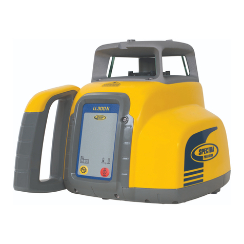
Spectra LL300N manual

Spectra

Spectra LL300N manual

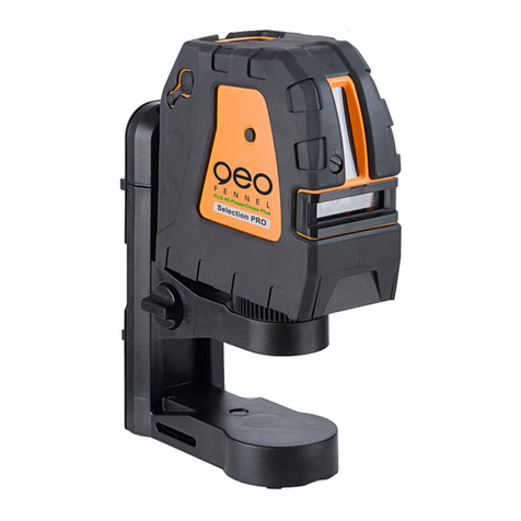
geo-FENNEL Selection PRO FLG 40-PowerCross GREEN SP user manual

geo-FENNEL

geo-FENNEL Selection PRO FLG 40-PowerCross GREEN SP user manual

Nedo Crossliner 4 operating instructions

Nedo

Nedo Crossliner 4 operating instructions

Lasertec FX360G instruction manual

Lasertec

Lasertec FX360G instruction manual

Flex ALC 8 Original operating instructions

Flex

Flex ALC 8 Original operating instructions

Cocraft HL 20-SG Original instructions

Cocraft

Cocraft HL 20-SG Original instructions

Johnson 40-6692 instruction manual

Johnson

Johnson 40-6692 instruction manual

LaserLiner SuperCross-Laser SCL 2 operating instructions

LaserLiner

LaserLiner SuperCross-Laser SCL 2 operating instructions

Leica iCON robot 60 user manual

Leica

Leica iCON robot 60 user manual

LaserLiner ActiveFinder XP user manual

LaserLiner

LaserLiner ActiveFinder XP user manual

imex EL20 manual

imex

imex EL20 manual

Fixturlaser NXA D I-0912 user manual

Fixturlaser

Fixturlaser NXA D I-0912 user manual

Skil 560 Original instructions

Skil

Skil 560 Original instructions

Metrica 33806 Operation manual

Metrica

Metrica 33806 Operation manual

manuals.online logo
manuals.online logoBrands
  • About & Mission
  • Contact us
  • Privacy Policy
  • Terms and Conditions

Copyright 2025 Manuals.Online. All Rights Reserved.

-1 -
DW079LG T2 & DCE079G T2
Series Service Manual
( V1.0/2023)
DW079LR T2 & DCE079R T2
-2 -
Main part diagram
Top Cover
Mid Secon
Base
Ridge Prism
Housing
Baery
Keypanel
Tripod
Aachment
-3 -
Maintenance step
2. Remove 4 screws and 3 self-tapping screws to take off top cover.
1. Remove 4 screws to take off Glass Cover Frame
..
Glass Cover
Frame
4 x Screws
Top cover
4 x Screws
3 x Self-tapping
Screws
3. Remove 4 screws and 3 self-tapping screws to take off Mid Section..
4 x Screws
3 x Self-tapping
Screws
-5 -
4. Below is a list of the main parts. Replace or repair these parts
according to the troubleshooting section.
Counter
Photo-Eye PCBA
Alarm Spring
Stepping motor
A&B
Compensaon
glass
Upper motor
Main PCBA
Supporng
Frame
Four M2.5
screws
Main PCBA
Main PCBA
Main PCBA
Main PCBA
907250
907250 NRL-MB-005_A11 DCE079R T2
DCE079G T2
907252 NRL-MB-005_A13
DW079LR T2
DW079LG T2
907251 NRL-MB-005_A12
907253 NRL-MB-005_A14
Support body
with Laser
Support body
with Laser
-6 -
Baery pack
Membrane
Switch
-7 -
906138 MPP2-keypad-002
Membrane Switch
(DW079LG& DCE079G)
906137 MPP2-keypad-001
Membrane Switch
(DW079LR& DCE079R)
traPniaMgnitoohselbuorTtcefeD
Horizontal application
defective
Check x-axis and y-axis bubble circuit
board connection cable ,or replace the
Membrane Switch
Calibration can't saved
Replace the storage IC
Main PCBA
Calibration limit beyond
precision scope Adjust the compensation glass /
Weak beam Replace the laser
Uneveling Replace stepping motor 904290 NRL800HT-01-02_04
Stepper Motor
Light is out of working Replace the Membrane Switch
Unit won't receive
remote control signal. Check receiver connection cable /
Vertical application
defective
Check z-axis bubble circuit board
connection cable ,or replace the
Membrane Switch
Rotation head loose from
frame. /wercsehtnetsaF
Battery indicator lights
flash
Battery voltage is low, need to
recharge /
No alarm Replace Main PCBA
Scan function defective Replace
Slope out of tolerance
Loosen the four M2.5 screws on the Main
PCBA. Move the Main PCBA
left or right to correct the slope.
Tighten the screws.
/
Unable to enter the
calibration mode Replace main PCBA
Button doesn't work Data cable looses ,reinstall the data
cable
/
Main PCBA
Main PCBA
906484 DW080LGS-01-01_88
Main Laser Module(DW079LG)
906482 MPP-01-01_88
Main Laser Module(DW079LR)
906485 DW079LG-00-00_88
Main Laser Module(DCE079G)
906482 MPP-01-01_88
Main Laser Module(DCE079R)
906138 MPP2-keypad-002
Membrane Switch(GREEN)
906137 MPP2-keypad-001
Membrane Switch(RED)
906138 MPP2-keypad-002
Membrane Switch(GREEN)
906137 MPP2-keypad-001
Membrane Switch(RED)
905243 NRL-ECV-001_A20
Counter Photo-Eye PCBA
-8 -
5. Calibrate the repaired instrument.
1) Turn power on and let the instrument find its level , after the
instrument is level (need about 1 minute), switch it off;
2) Press and hold Slope button then press Power button
All the indicators will light up , indicating instrument is in calibration
mode;
to select X and Y axis.
select X direction adjustment, the X indicator will light up;
4) Press scan mode button to select dot mode; press
four times you can see the laser beam;
5) Adjust the beam to X mark and target by turn
(0 degree);
6) Adjust the beam to reference line by pressing or .
7) Rotate instrument 180 degrees with X facing the same target.
Calibrate X - axis
Calibrate Y - axis
Prism Cover
3)Press and hold RPM button or press
-9 -
8) Adjust the beam to reference line by pressing or
9) After adjustment is complete , press and hold slop button
to save the setting. All the indicators will light up & Buzzer sounds
indicating calibration is completed and setting are saved .
10) After saving the changes, restart the unit, check the X –axis for
accuracy; you should calibrate your instrume
nt again if accuracy is
over spec.
11) Use the same way tocalibrate Y-axis.
12) Place the instrument on the vertical application to calibrate Z-axis ,
repeat step 1 and step 2, the X&Y indicators will light up , adjust the
beam to reference line by pressing or , then repeat step 9
to save the calibration.
calibration saved