DeWalt 20V MAX DCN890 User manual

If you have questions or comments, contact us.
Pour toute question ou tout commentaire, nous contacter.
Si tiene dudas o comentarios, contáctenos.
1-800-4-DeWALT
Instruction Manual
Guide D’utilisation
Manual de instrucciones
DCN890
20V MAX* Concrete Nailer
Cloueuse pour béton 20V MAX*
Clavadora para concreto de 20 V MAX*
final page size: 8.5 x 5.5 in

If you have questions or comments, contact us.
Pour toute question ou tout commentaire, nous contacter.
Si tiene dudas o comentarios, contáctenos.
1-800-4-DEWALT
Instruction Manual
Guide D’utilisation
Manual de instrucciones
DCN890
20V MAX* Concrete Nailer
Cloueuse pour béton 20V MAX*
Clavadora para concreto de 20 V MAX*
final page size: 8.5 x 5.5 in

ENGLISH
English (original instructions) 1
Français (traduction de la notice d’instructions originale) 19
Español (traducido de las instrucciones originales) 38

ENGLISH
1
English (original instructions)
Definitions: Safety Alert Symbols and Words
This instruction manual uses the following safety alert symbols and words to alert you to hazardous situations and your risk
of personal injury or property damage.
DANGER: Indicates an imminently hazardous situation which, if not avoided, will result in death or seriousinjury.
WARNING: Indicates a potentially hazardous situation which, if not avoided, could result in death or seriousinjury.
CAUTION: Indicates a potentially hazardous situation which, if not avoided, may result in minor or moderateinjury.
(Used without word) Indicates a safety related message.
NOTICE: Indicates a practice not related to personal injury which, if not avoided, may result in propertydamage.
WARNING! Read all safety warnings
and all instructions. Failure to follow the
warnings and instructions may result in
electric shock, fire and/or seriousinjury.
WARNING: To reduce the risk of injury, read
the instructionmanual.
If you have any questions or comments about
this or any
DeWALT
tool, call us toll free at:
1-800-4-
DeWALT
(1-800-433-9258).
1 Trigger
2 Trigger lock-off
3 Power Selection Switch
4 Utility hook
5 Contact trip release lever
6 Contact trip
7 Removable top stand
8 Stall release lever
9 Low battery & jam/stall
indicator lights (x2)
10 Battery pack
11 Battery release button
12 Magazine
13 Magazine support leg
14 Magazine release lever
15 Pusher
Fig. A
1
2
5
6
7
8
9
10
11
12
13
14
15
4
3

ENGLISH
2
GENERAL POWER TOOL SAFETY WARNINGS
WARNING! Read all safety warnings and all
instructions. Failure to follow the warnings and
instructions may result in electric shock, fire and/or
seriousinjury.
SAVE ALL WARNINGS AND
INSTRUCTIONS FOR FUTURE
REFERENCE
The term “power tool” in the warnings refers to your mains-
operated (corded) power tool or battery-operated (cordless)
powertool.
1) Work Area Safety
a ) Keep work area clean and well lit. Cluttered or dark
areas inviteaccidents.
b ) Do not operate power tools in explosive
atmospheres, such as in the presence of
flammable liquids, gases or dust. Power tools
create sparks which may ignite the dust orfumes.
c ) Keep children and bystanders away while
operating a power tool. Distractions can cause you
to losecontrol.
2) Electrical Safety
a ) Power tool plugs must match the outlet. Never
modify the plug in any way. Do not use any
adapter plugs with earthed (grounded) power
tools. Unmodified plugs and matching outlets will
reduce risk of electricshock.
b ) Avoid body contact with earthed or grounded
surfaces such as pipes, radiators, ranges and
refrigerators. There is an increased risk of electric
shock if your body is earthed orgrounded.
c ) Do not expose power tools to rain or wet
conditions. Water entering a power tool will increase
the risk of electricshock.
d ) Do not abuse the cord. Never use the cord for
carrying, pulling or unplugging the power tool.
Keep cord away from heat, oil, sharp edges or
moving parts. Damaged or entangled cords increase
the risk of electricshock.
e ) When operating a power tool outdoors, use an
extension cord suitable for outdoor use. Use of
a cord suitable for outdoor use reduces the risk of
electricshock.
f ) If operating a power tool in a damp location
is unavoidable, use a ground fault circuit
interrupter (GFCI) protected supply. Use of a GFCI
reduces the risk of electricshock.
3) Personal Safety
a ) Stay alert, watch what you are doing and use
common sense when operating a power tool. Do
not use a power tool while you are tired or under
the influence of drugs, alcohol or medication. A
moment of inattention while operating power tools
may result in serious personalinjury.
b ) Use personal protective equipment. Always wear
eye protection. Protective equipment such as dust
mask, non-skid safety shoes, hard hat, or hearing
protection used for appropriate conditions will reduce
personalinjuries.
c ) Prevent unintentional starting. Ensure the
switch is in the off position before connecting to
power source and/or battery pack, picking up or
carrying the tool. Carrying power tools with your
finger on the switch or energizing power tools that
have the switch on invitesaccidents.
d ) Remove any adjusting key or wrench before
turning the power tool on. A wrench or a key left
attached to a rotating part of the power tool may
result in personalinjury.
e ) Do not overreach. Keep proper footing and
balance at all times. This enables better control of
the power tool in unexpectedsituations.
f ) Dress properly. Do not wear loose clothing or
jewelry. Keep your hair, clothing and gloves
away from moving parts. Loose clothes, jewelry or
long hair can be caught in movingparts.
g ) If devices are provided for the connection of dust
extraction and collection facilities, ensure these
are connected and properly used. Use of dust
collection can reduce dust-relatedhazards.
4) Power Tool Use and Care
a ) Do not force the power tool. Use the correct
power tool for your application. The correct power
tool will do the job better and safer at the rate for
which it wasdesigned.
b ) Do not use the power tool if the switch does not
turn it on and off. Any power tool that cannot be
controlled with the switch is dangerous and must
berepaired.
c ) Disconnect the plug from the power source and/
or the battery pack from the power tool before
making any adjustments, changing accessories,
or storing power tools. Such preventive safety
measures reduce the risk of starting the power
toolaccidentally.
d ) Store idle power tools out of the reach of children
and do not allow persons unfamiliar with the
power tool or these instructions to operate the
power tool. Power tools are dangerous in the hands
of untrainedusers.
e ) Maintain power tools. Check for misalignment or
binding of moving parts, breakage of parts and
any other condition that may affect the power
tool’s operation. If damaged, have the power
tool repaired before use. Many accidents are
caused by poorly maintained powertools.
f ) Keep cutting tools sharp and clean. Properly
maintained cutting tools with sharp cutting edges are
less likely to bind and are easier tocontrol.

ENGLISH
3
g ) Use the power tool, accessories and tool bits, etc.
in accordance with these instructions, taking
into account the working conditions and the
work to be performed. Use of the power tool for
operations different from those intended could result
in a hazardoussituation.
5) Battery Tool Use and Care
a ) Recharge only with the charger specified by the
manufacturer. A charger that is suitable for one type
of battery pack may create a risk of fire when used
with another batterypack.
b ) Use power tools only with specifically designated
battery packs. Use of any other battery packs may
create a risk of injury andfire.
c ) When battery pack is not in use, keep it away
from other metal objects, like paper clips, coins,
keys, nails, screws, or other small metal objects,
that can make a connection from one terminal to
another. Shorting the battery terminals together may
cause burns or afire.
d ) Under abusive conditions, liquid may be ejected from
the battery; avoid contact. If contact accidentally
occurs, flush with water. If liquid contacts eyes,
additionally seek medical help. Liquid ejected from
the battery may cause irritation orburns.
6) Service
a ) Have your power tool serviced by a qualified
repair person using only identical replacement
parts. This will ensure that the safety of the power
tool ismaintained.
Nailer Safety Warnings
• Always assume that the tool contains fasteners.
Careless handling of the nailer can result in unexpected
firing of fasteners and personalinjury.
• Do not point the tool towards yourself or anyone
nearby. Unexpected triggering could discharge a fastener
causing aninjury.
• Do not actuate the tool unless the tool is placed
firmly against the workpiece. If the tool is not in
contact with the workpiece, the fastener may be deflected
away from yourtarget.
• Disconnect the tool from the power source when the
fastener jams in the tool. While removing a jammed
fastener, the nailer may be accidentally activated if it is
pluggedin.
• Do not use this nailer for fastening electrical cables.
It is not designed for electric cable installation and may
damage the insulation of electric cables thereby causing
electric shock or firehazards.
• Never operate tool with Magazine disengaged or
separated from tool.
Additional Nailer Safety Warnings
WARNING: When using any nailer, all safety
precautions, as outlined below, should be followed
to avoid the risk of death or serious injury. Read and
understand all instructions before operating thetool.
• Hold tool by insulated gripping surfaces when
performing an operation where the pin may
contact hidden wiring. Contact with a “live” wire will
make exposed metal parts of the tool “live” and shock
theoperator.
• Always wear appropriate personal hearing and
other protection during use. Under some conditions
and duration of use, noise from this product may
contribute to hearingloss.
• Disconnect battery pack from the tool when not in
use. Always remove battery pack and remove fasteners
from magazine before leaving the area or passing the
tool to another operator. Do not carry tool to another
work area in which changing location involves the use
of scaffoldings, stairs, ladders, and the like, with battery
pack connected. Do not make adjustments, perform
maintenance or clear jammed fasteners while battery is
inplace.
• Always use trigger lock-off when tool is not in
immediate use. Using the trigger lock-off will prevent
accidental discharge.
• Do not remove, tamper with, or otherwise cause
the tool, trigger or trigger lock-off, to become
inoperable. Do not tape or tie trigger in the on position.
Do not remove spring from contact trip. Make daily
inspections for free movement of trigger. Uncontrolled
discharge couldresult.
• Inspect tool before use. Do not operate a tool if any
portion of the tool, trigger, or trigger lock-off is
inoperable, disconnected, altered, or not working
properly. Damaged parts or missing parts should be
repaired or replaced before use. Refer toRepairs.
• Do not alter or modify the tool in anyway.
• Always assume that the tool containsfasteners.
• Do not point the tool at co-workers or yourself at
any time. No horseplay! Work safe! Respect the tool as a
workingimplement.
• Keep bystanders, children, and visitors away while
operating a power tool. Distractions can cause you to
lose control. When tool is not in use, it should be locked in
a safe place, out of the reach ofchildren.
• Do not overreach. Maintain proper footing and
balance at all times. Loss of balance may cause
personal injury.
• Use the tool only for its intended use. Do not
discharge fasteners into open air or any material
too hard for the pin to penetrate. Do not use the
body of the tool or top cap as a hammer. Discharged
pin may follow unexpected path and causeinjury.
• Always keep fingers clear of contact trip to prevent
injury from inadvertent release of thepin.

ENGLISH
4
• Refer to the Maintenance and Repairs sections for
detailed information on the proper maintenance of
thetool.
• Always operate the tool in a clean, lighted area.
Be sure the work surface is clear of any debris and be
careful not to lose footing when working in elevated
environments such asrooftops.
• Fasteners must be driven straight into the material.
Do not tilt the nailer while driving fasteners. Personal
injury can result from ricocheted or jammedpins.
• Keep hands and body parts clear of immediate
workarea.
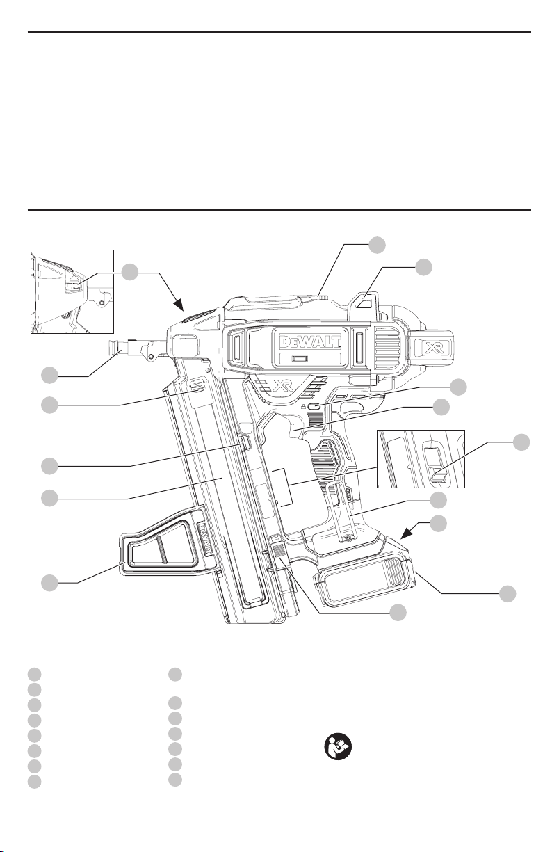
WARNING: To avoid injury keep hands and body
away from the front discharge area of thetool.
• Do not use tool in the presence of flammable dust,
gases or fumes. This tool produces sparks that can ignite
gases or dust causing an explosion. Driving a pin into
another pin may also cause aspark.
• Keep face and body parts away from back of the tool
cap when working in restricted areas. Sudden recoil
can result in impact to the body, especially when nailing
into hard or densematerial.
• Grip tool firmly to maintain control while allowing
tool to recoil away from work surface as fastener
isdriven.
• Be aware of material thickness when using nailer. A
protruding pin may causeinjury.
• Do not drive pins blindly into walls, floors or other
work areas. Fasteners driven into live electrical wires,
plumbing, or other types of obstructions can result
ininjury.
• Stay alert, watch what you are doing and use
common sense when operating a power tool. Do not
use tool while tired or under the influence of drugs,
alcohol, or medication. A moment of inattention
while operating power tools may result in serious
personalinjury.
Additional Safety Information
WARNING: ALWAYS use safety glasses. Everyday
eyeglasses are NOT safety glasses. Also use face or
dust mask if cutting operation is dusty. ALWAYS WEAR
CERTIFIED SAFETYEQUIPMENT:
• ANSI Z87.1 eye protection (CAN/CSA Z94.3),
• ANSI S12.6 (S3.19) hearing protection,
• NIOSH/OSHA/MSHA respiratoryprotection.
WARNING: Some dust created by power sanding,
sawing, grinding, drilling, and other construction
activities contains chemicals known to the State
of California to cause cancer, birth defects or
other reproductive harm. Some examples of these
chemicalsare:
• lead from lead-based paints,
• crystalline silica from bricks and cement and other
masonry products, and
• arsenic and chromium from chemically-
treatedlumber.
Your risk from these exposures varies, depending on how
often you do this type of work. To reduce your exposure to
these chemicals: work in a well ventilated area, and work with
approved safety equipment, such as those dust masks that are
specially designed to filter out microscopicparticles.
• Avoid prolonged contact with dust from power
sanding, sawing, grinding, drilling, and other
construction activities. Wear protective clothing and
wash exposed areas with soap and water. Allowing
dust to get into your mouth, eyes, or lay on the skin may
promote absorption of harmfulchemicals.
WARNING: Use of this tool can generate and/
or disperse dust, which may cause serious and
permanent respiratory or other injury. Always use
NIOSH/OSHA approved respiratory protection
appropriate for the dust exposure. Direct particles
away from face andbody.
WARNING: Always wear proper personal hearing
protection that conforms to ANSI S12.6 (S3.19)
during use. Under some conditions and duration
of use, noise from this product may contribute to
hearingloss.
CAUTION: When not in use, place tool on its side
on a stable surface where it will not cause a
tripping or falling hazard. Some tools with large
battery packs will stand upright on the battery pack
but may be easily knockedover.
• Air vents often cover moving parts and should be
avoided. Loose clothes, jewelry or long hair can be
caught in movingparts.
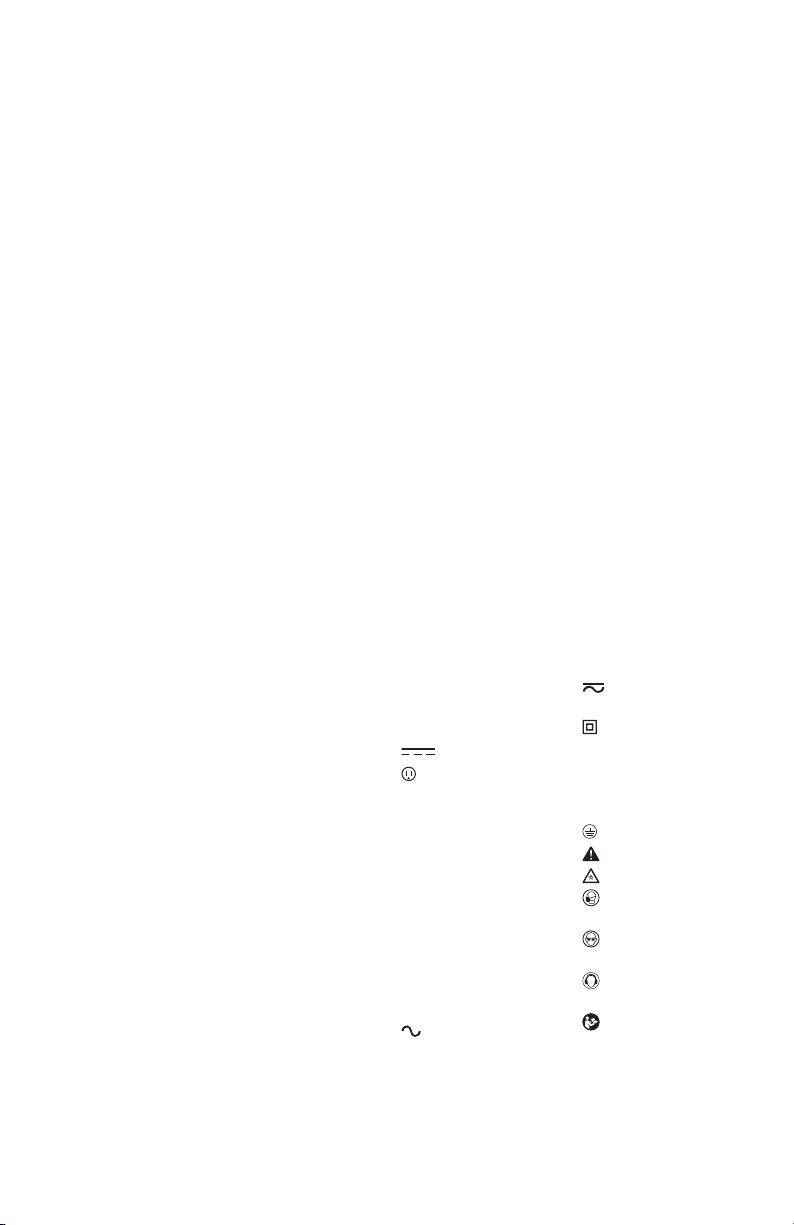
The label on your tool may include the following symbols. The
symbols and their definitions are asfollows:
V.........................volts
Hz .......................hertz
min.....................minutes
or DC......direct current
......................Class I Construction
(grounded)
…/min..............per minute
BPM....................beats per minute
IPM.....................impacts per minute
RPM....................revolutions per
minute
sfpm ...................surface feet per
minute
SPM....................strokes per minute
A.........................amperes
W........................watts
or AC........... alternating current
or AC/DC....alternating or
direct current
......................Class II
Construction
(double insulated)
no.......................no load speed
n.........................rated speed
......................earthing terminal
.....................safety alert symbol
.....................visible radiation
.....................wear respiratory
protection
.....................wear eye
protection
.....................wear hearing
protection
.....................read all
documentation
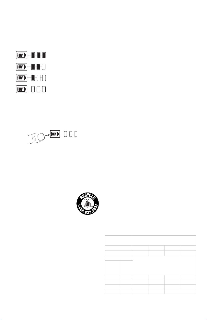
BATTERIES AND CHARGERS
The battery pack is not fully charged out of the carton.
Before using the battery pack and charger, read the
safety instructions below and then follow charging

ENGLISH
5
proceduresoutlined. When ordering replacement battery
packs, be sure to include the catalog number andvoltage.
Your tool uses a
DeWALT
charger. Be sure to read all safety
instructions before using your charger. Consult the chart
at the end of this manual for compatibility of chargers and
batterypacks.
READ ALL INSTRUCTIONS
Important Safety Instructions for All
Battery Packs
WARNING: Read all safety warnings and all
instructions for the battery pack, charger and
power tool. Failure to follow the warnings and
instructions may result in electric shock, fire and/
or serious injury.
• Do not charge or use the battery pack in explosive
atmospheres, such as in the presence of flammable
liquids, gases or dust. Inserting or removing the battery
pack from the charger may ignite the dust orfumes.
• NEVER force the battery pack into the charger. DO
NOT modify the battery pack in any way to fit into
a non-compatible charger as battery pack may
rupture causing serious personal injury. Consult
the chart at the end of this manual for compatibility of
batteries andchargers.
• Charge the battery packs only in designated
DeWALT
chargers.
• DO NOT splash or immerse in water or otherliquids.
• Do not store or use the tool and battery pack in
locations where the temperature may reach or
exceed 104°F (40°C) (such as outside sheds or metal
buildings in summer). For best life store battery packs in
a cool, drylocation.
NOTE: Do not store the battery packs in a tool with
the trigger switch locked on. Never tape the trigger
switch in the ONposition.
• Do not incinerate the battery pack even if it is
severely damaged or is completely worn out. The
battery pack can explode in a fire. Toxic fumes and
materials are created when lithium ion battery packs
areburned.
• If battery contents come into contact with the skin,
immediately wash area with mild soap and water. If
battery liquid gets into the eye, rinse water over the open
eye for 15 minutes or until irritation ceases. If medical
attention is needed, the battery electrolyte is composed of
a mixture of liquid organic carbonates and lithiumsalts.
• Contents of opened battery cells may cause
respiratory irritation. Provide fresh air. If symptoms
persist, seek medicalattention.
WARNING: Burn hazard. Battery liquid may be
flammable if exposed to spark orflame.
WARNING: Fire hazard. Never attempt to open the
battery pack for any reason. If the battery pack case
is cracked or damaged, do not insert into the charger.
Do not crush, drop or damage the battery pack. Do
not use a battery pack or charger that has received a
sharp blow, been dropped, run over or damaged in
any way (e.g., pierced with a nail, hit with a hammer,
stepped on). Damaged battery packs should be
returned to the service center forrecycling.
Transportation
WARNING: Fire hazard. Do not store or carry the
battery pack so that metal objects can contact
exposed battery terminals. For example, do
not place the battery pack in aprons, pockets, tool
boxes, product kit boxes, drawers, etc., with loose
nails, screws, keys, etc. Transporting batteries
can possibly cause fires if the battery terminals
inadvertently come in contact with conductive
materials such as keys, coins, hand tools and the
like. The US Department of Transportation Hazardous
Material Regulations (HMR) actually prohibit
transporting batteries in commerce or on airplanes in
carry-on baggage UNLESS they are properly protected
from short circuits. So when transporting individual
battery packs, make sure that the battery terminals
are protected and well insulated from materials that
could contact them and cause a short circuit.
Shipping the
DeWALT
FLEXVOLT™ Battery
The D
e
WALT FLEXVOLT™ battery has two modes: Use and
Shipping.
Use Mode: When the FLEXVOLT™ battery stands alone or is
in a D
e
WALT 20V Max* product, it will operate as a 20V Max*
battery. When the FLEXVOLT™ battery is in a 60V Max* or a
120V Max* (two 60V Max* batteries) product, it will operate
as a 60V Max* battery.
Shipping Mode: When
the cap is attached to the
FLEXVOLT™ battery, the
battery is in Shipping Mode.
Strings of cells are electrically
disconnected within the pack resulting in three batteries
with a lower Watt hour (Wh) rating as compared to one
battery with a higher Watt hour rating. This increased
quantity of three batteries with the lower Watt hour rating
can exempt the pack from certain shipping regulations that
are imposed upon the higher Watt hour batteries.
The battery label indicates two Watt hour ratings (see
example). Depending on how the battery is shipped, the
appropriate Watt hour rating must be used to determine
the applicable shipping requirements. If utilizing the
shipping cap, the pack will be considered 3 batteries at
the Watt hour rating indicated for “Shipping”. If shipping
without the cap or in a tool, the pack will be considered one
battery at the Watt hour rating indicated next to “Use”.
USE: 120 Wh Shipping: 3 x 40 Wh
Example of Use and Shipping Label Marking
For example, Shipping Wh rating might indicate 3 x 40 Wh,
meaning 3 batteries of 40 Watt hours each. The Use Wh
rating might indicate 120 Wh (1 battery implied).

ENGLISH
6
Fuel Gauge Battery Packs (Fig. B)
Some
DeWALT
battery packs include a fuel gauge which
consists of three green LED lights that indicate the level of
charge remaining in the batterypack.
The fuel gauge is an indication of approximate levels of
charge remaining in the battery pack according to the
followingindicators:
75–100% charged
51–74% charged
< 50% charged
Pack needs to be charged
To actuate the fuel gauge, press and hold the fuel gauge
button. A combination of the three green LED lights will
illuminate designating the level of charge left. When the
level of charge in the battery is below the usable limit, the
fuel gauge will not illuminate and the battery will need to
berecharged.
Fig. B
NOTE: The fuel gauge is only an indication of the charge left
on the battery pack. It does not indicate tool functionality
and is subject to variation based on product components,
temperature and end-userapplication.
For more information regarding fuel gauge battery packs,
please contact call 1-800-4-
DeWALT
(1-800-433-9258) or
visit our website www.dewalt.com.
The RBRC® Seal
The RBRC® (Rechargeable Battery
Recycling Corporation) Seal on the nickel
cadmium, nickel metal hydride or lithium-
ion batteries (or battery packs) indicates
that the costs to recycle these batteries
(or battery packs) at the end of their useful life have already
been paid by
DeWALT
. In some areas, it is illegal to place
spent nickel cadmium, nickel metal hydride or lithium-ion
batteries in the trash or municipal solid waste stream and
the Call2Recycle® program provides an environmentally
consciousalternative.
Call 2 Recycle, Inc., in cooperation with
DeWALT
and other
battery users, has established the program in the United
States and Canada to facilitate the collection of spent nickel
cadmium, nickel metal hydride or lithium-ion batteries. Help
protect our environment and conserve natural resources by
returning the spent nickel cadmium, nickel metal hydride
or lithium-ion batteries to an authorized
DeWALT
service
center or to your local retailer for recycling. You may also
contact your local recycling center for information on
where to drop off the spent battery. RBRC® is a registered
trademark of Call 2 Recycle,Inc.
Important Safety Instructions for All
Battery Chargers
WARNING: Read all safety warnings and all
instructions for the battery pack, charger and
power tool. Failure to follow the warnings and
instructions may result in electric shock, fire and/
or serious injury.
• DO NOT attempt to charge the battery pack with
any chargers other than the ones in this manual.
The charger and battery pack are specifically designed to
worktogether.
• These chargers are not intended for any uses other
than charging
DeWALT
rechargeable batteries.
Any other uses may result in risk of fire, electric shock
orelectrocution.
• Do not expose the charger to rain orsnow.
• Pull by the plug rather than the cord when
disconnecting the charger. This will reduce the risk of
damage to the electric plug andcord.
• Make sure that the cord is located so that it will not
be stepped on, tripped over or otherwise subjected
to damage orstress.
• Do not use an extension cord unless it is absolutely
necessary. Use of improper extension cord could result in
risk of fire, electric shock orelectrocution.
• When operating a charger outdoors, always provide
a dry location and use an extension cord suitable
for outdoor use. Use of a cord suitable for outdoor use
reduces the risk of electricshock.
• An extension cord must have adequate wire size
(AWG or American Wire Gauge) for safety. The smaller
the gauge number of the wire, the greater the capacity
of the cable, that is, 16 gauge has more capacity than 18
gauge. An undersized cord will cause a drop in line voltage
resulting in loss of power and overheating. When using
more than one extension to make up the total length,
be sure each individual extension contains at least the
minimum wire size. The following table shows the correct
size to use depending on cord length and nameplate
ampere rating. If in doubt, use the next heavier gauge. The
lower the gauge number, the heavier thecord.
Minimum Gauge for Cord Sets
Volts Total Length of Cord in Feet
(meters)
120 V 25 (7.6) 50 (15.2) 100 (30.5) 150 (45.7)
240 V 50 (15.2) 100 (30.5) 200 (61.0) 300 (91.4)
Ampere Rating
American Wire Gauge
More
Than
Not
More
Than
0 6 18 16 16 14
610 18 16 14 12
10 12 16 16 14 12
12 16 14 12 Not Recommended
• Do not place any object on top of the charger or
place the charger on a soft surface that might block
the ventilation slots and result in excessive internal

ENGLISH
7
heat. Place the charger in a position away from any heat
source. The charger is ventilated through slots in the top
and the bottom of thehousing.
• Do not operate the charger with a damaged cord
orplug.
• Do not operate the charger if it has received a sharp
blow, been dropped or otherwise damaged in any
way. Take it to an authorized servicecenter.
• Do not disassemble the charger; take it to an
authorized service center when service or repair
is required. Incorrect reassembly may result in a risk of
electric shock, electrocution orfire.
• Disconnect the charger from the outlet before
attempting any cleaning. This will reduce the risk of
electric shock. Removing the battery pack will not reduce
thisrisk.
• NEVER attempt to connect 2 chargerstogether.
• The charger is designed to operate on standard
120V household electrical power. Do not attempt to
use it on any other voltage. This does not apply to the
vehicularcharger.
WARNING: Shock hazard. Do not allow any liquid to
get inside the charger. Electric shock mayresult.
WARNING:Burn hazard. Do not submerge the
battery pack in any liquid or allow any liquid to
enter the battery pack. Never attempt to open the
battery pack for any reason. If the plastic housing of
the battery pack breaks or cracks, return to a service
center for recycling.
CAUTION: Burn hazard. To reduce the risk of injury,
charge only
DeWALT
rechargeable battery packs.
Other types of batteries may overheat and burst
resulting in personal injury and propertydamage.
NOTICE: Under certain conditions, with the charger
plugged into the power supply, the charger can
be shorted by foreign material. Foreign materials
of a conductive nature, such as, but not limited to,
grinding dust, metal chips, steel wool, aluminum
foil or any buildup of metallic particles should be
kept away from the charger cavities. Always unplug
the charger from the power supply when there is no
battery pack in the cavity. Unplug the charger before
attempting toclean.
Charging a Battery (Fig. C)
1. Plug the charger into an appropriate outlet before
inserting battery pack.
10
11
Fig. C
2. Insert the battery pack10 into the charger, making sure
the battery pack is fully seated in the charger. The red
(charging) light will blink continuously indicating that
the charging process has started.
3. The completion of charge will be indicated by the red
light remaining ON continuously. The battery pack is
fully charged and may be used at this time or left in the
charger. To remove the battery pack from the charger,
push the battery release button11 on the battery pack.
NOTE: To ensure maximum performance and life of lithium-
ion battery packs, charge the battery pack fully before first
use.
Charger Operation
Refer to the indicators below for the charge status of the
battery pack.
DCB101
Charging
Fully Charged
Hot/Cold Pack Delay
Problem Pack or Charger
DCB107, DCB112, DCB113, DCB115, DCB118, DCB132
Charging
Fully Charged
Hot/Cold Pack Delay*
*DCB107, DCB112, DCB113, DCB115, DCB118, DCB132:
The red light will continue to blink, but a yellow indicator
light will be illuminated during this operation. Once the
battery pack has reached an appropriate temperature, the
yellow light will turn off and the charger will resume the
charging procedure.
The compatible charger(s) will not charge a faulty battery
pack. The charger will indicate faulty battery pack by
refusing to light or by displaying a problem pack or charger
blink pattern.
NOTE: This could also mean a problem with a charger.
If the charger indicates a problem, take the charger and
battery pack to be tested at an authorized service center.
Hot/Cold Pack Delay
When the charger detects a battery pack that is too hot
or too cold, it automatically starts a Hot/Cold Pack Delay,
suspending charging until the battery pack has reached an
appropriate temperature. The charger then automatically
switches to the pack charging mode. This feature ensures
maximum battery pack life.
A cold battery pack will charge at a slower rate than a warm
battery pack. The battery pack will charge at that slower rate
throughout the entire charging cycle and will not return to
maximum charge rate even if the battery pack warms.

ENGLISH
8
The DCB118 charger is equipped with an internal fan
designed to cool the battery pack. The fan will turn on
automatically when the battery pack needs to be cooled.
Never operate the charger if the fan does not operate
properly or if ventilation slots are blocked. Do not permit
foreign objects to enter the interior of the charger.
Electronic Protection System
Li-Ion tools are designed with an Electronic Protection
System that will protect the battery pack against
overloading, overheating or deep discharge.
The tool will automatically turn off if the Electronic
Protection System engages. If this occurs, place the lithium-
ion battery pack on the charger until it is fully charged.
Wall Mounting
DCB107, DCB112, DCB113, DCB115, DCB118, DCB132
These chargers are designed to be wall mountable or to
sit upright on a table or work surface. If wall mounting,
locate the charger within reach of an electrical outlet,
and away from a corner or other obstructions which may
impede air flow. Use the back of the charger as a template
for the location of the mounting screws on the wall. Mount
the charger securely using drywall screws (purchased
separately) at least 1" (25.4 mm) long, with a screw head
diameter of 0.28–0.35" (7–9mm), screwed into wood to an
optimal depth leaving approximately 7/32" (5.5 mm) of the
screw exposed. Align the slots on the back of the charger
with the exposed screws and fully engage them in the slots.
Charger Cleaning Instructions
WARNING: Shock hazard. Disconnect the charger
from the AC outlet before cleaning. Dirt and grease
may be removed from the exterior of the charger using
a cloth or soft non-metallic brush. Do not use water or
any cleaning solutions.
Important Charging Notes
1. Longest life and best performance can be obtained if
the battery pack is charged when the air temperature is
between 65°F and 75°F (18°– 24°C). DO NOT charge
the battery pack in an air temperature below +40°F
(+4.5°C), or above +104°F (+40°C). This is important
and will prevent serious damage to the battery pack.
2. The charger and battery pack may become warm to the
touch while charging. This is a normal condition, and
does not indicate a problem. To facilitate the cooling of
the battery pack after use, avoid placing the charger or
battery pack in a warm environment such as in a metal
shed or an uninsulated trailer.
3. If the battery pack does not charge properly:
a. Check operation of receptacle by plugging in a lamp
or other appliance;
b. Check to see if receptacle is connected to a light
switch which turns power off when you turn out the
lights;
c. Move the charger and battery pack to a location
where the surrounding air temperature is
approximately 65°F– 75°F (18° –24°C);
d. If charging problems persist, take the tool, battery
pack and charger to your local service center.
4. The battery pack should be recharged when it fails to
produce sufficient power on jobs which were easily
done previously. DO NOT CONTINUE to use under these
conditions. Follow the charging procedure. You may
also charge a partially used pack whenever you desire
with no adverse effect on the battery pack.
5. Foreign materials of a conductive nature such as, but
not limited to, grinding dust, metal chips, steel wool,
aluminum foil, or any buildup of metallic particles
should be kept away from charger cavities. Always
unplug the charger from the power supply when there
is no battery pack in the cavity. Unplug the charger
before attempting to clean.
6. Do not freeze or immerse the charger in water or any
other liquid.
Storage Recommendations
1. The best storage place is one that is cool and dry, away
from direct sunlight and excess heat or cold.
2. For long storage, it is recommended to store a fully
charged battery pack in a cool dry place out of the
charger for optimal results.
NOTE: Battery packs should not be stored completely
depleted of charge. The battery pack will need to be
recharged before use.
SAVE THESE INSTRUCTIONS FOR
FUTURE USE
COMPONENTS (FIG. A)
WARNING: Never modify the power tool or any part
of it. Damage or personal injury couldresult.
Refer to Figure A at the beginning of this manual for a
complete list ofcomponents.
Intended Use
Your concrete nailer is intended ONLY for use in driving
pins into structural steel/wood/concrete.
DO NOT use under wet conditions or in presence of
flammable liquids orgases.
Use ONLY pins that are recommended by
DeWALT
and
meet applicable building code requirements.
This tool is intended for use by construction professionals.
DO NOT let children come into contact with the tool.
Supervision is required when inexperienced operators use
thistool.

ENGLISH
9
TOOL SPECIFICATIONS
Actuation Mode Sequential
Voltage 20
Height 16.0" (406 mm)
Width 4.1" (104 mm)
Length 15.4" (390 mm)
Weight 9.3 lbs (4.218 kg)
Magazine Angle 15˚
Loading Capacity Up to 33 pins
PIN SPECIFICATIONS
Pin Lengths 1/2" - 2 1/4" (13 mm - 57 mm)
Shank Diameters .102" - .145" (2.6 mm - 3.7 mm)
Pin Stick Angles 15˚
Dry Fire Lock Out
The concrete nailer is equipped with a dry fire lockout which
prevents the tool from actuating when the magazine is
nearly empty. When 3 pins remain in the magazine, the tool
ceases to operate. Refer to LoadingtheTool to reload a
stick of collated pins.
ASSEMBLY AND ADJUSTMENTS
WARNING: To reduce the risk of serious personal
injury, turn unit off and remove the battery pack
before making any adjustments or removing/
installing attachments or accessories. An
accidental start-up can causeinjury.
Utility Hook (Fig. A, D)
The
DeWALT
cordless nailers include an integrated utility
hook4 and can be attached to either side of the tool to
accommodate left- or right-handed users.
If the hook is not desired at all, it can be removed from
thetool.
To Remove Utility Hook
1. Remove battery pack from tool.
2. To switch the tool from right- to left-hand usage simply
remove the screw17 from the opposite side of the tool
and re attache the utility hook4 on the other side.
3. Replace battery pack.
Fig. D
17
WARNING: Remove pins from magazine before
making any adjustments or servicing this tool. Failure
to do so may result in serious injury.
WARNING: Disconnect battery pack from tool before
making any adjustments, changing accessories,
servicing, or moving the tool. Such preventative
safety measures reduce the risk of starting the
toolaccidentally.
CAUTION: When not in use, place tool on its side on
a stable surface where it will not cause a tripping or
falling hazard. Some tools with large battery packs
will stand upright on the battery pack but may be
easily knocked over.
OPERATION
WARNING: To reduce the risk of serious personal
injury, turn unit off and remove the battery pack
before making any adjustments or removing/
installing attachments or accessories. An
accidental start-up can causeinjury.
WARNING: Read the section titled Nailer Safety
Warnings at the beginning of this manual. Always
wear eye and ear protection when operating this
tool. Keep the nailer pointed away from yourself and
others. For safe operation, complete the following
procedures and checks before each use of thenailer.
1. Wear proper eye, hearing and respiratoryprotection.
2. Remove battery pack fromtool.
3. Lock the pusher in the back position and remove all pins
from themagazine.
4. Check for smooth and proper operation of contact
trip and pusher assemblies. Do not use tool if either
assembly is not functioning properly. NEVER use a tool
that has the contact trip restrained in the upposition.
5. NEVER use a tool that has damagedparts.
WARNING: To reduce the risk of personal injury,
disconnect battery pack from tool before performing
maintenance, clearing a jammed pin, leaving work
area, moving tool to another location or handing the
tool to anotherperson.
Installing and Removing the Battery Pack
(Fig. A)
NOTE: For best results, make sure your battery pack is
fullycharged.
To install the battery pack10 into the tool handle, align the
battery pack with the rails inside the tool’s handle and slide
it into the handle until the battery pack is firmly seated in
the tool and ensure that it does notdisengage.
To remove the battery pack from the tool, press the release
button11 and firmly pull the battery pack out of the tool
handle. Insert it into the charger as described in the charger
section of thismanual.

ENGLISH
10
Proper Hand Position (Fig. E)
WARNING: To reduce the risk of serious personal injury,
ALWAYS use proper hand position as shown.
WARNING: To reduce the risk of serious personal injury,
ALWAYS hold securely in anticipation of a sudden
reaction.
Proper hand position requires one hand on the main handle
as shown in Fig. E.
Fig. E
Preparing the Tool
NOTICE: NEVER spray or in
any other way apply lubricants
or cleaning solvents inside the
tool. This can seriously affect
the life and performance of
thetool.
NOTE: The battery pack is not fully charged out of the
carton. Follow instructions outlined (refer to Charging
ABattery).
1. Read the Nailer Safety Warnings section of
thismanual.
2. Wear eye and earprotection.
3. Remove battery fromtool.
4. Ensure magazine is empty of allfastners.
5. Check for smooth and proper operation of contact
trip and pusher assemblies. Do not use tool if either
assembly is not functioning properly. NEVER use
a tool that has the contact trip restrained in the
actuatedposition.
6. Keep tool pointed away from yourself andothers.
7. Insert fully charged batterypack.
Using the Trigger Lock-off (Fig. F)
WARNING: To reduce the risk of serious personal
injury, do not keep trigger depressed when tool is not
in use. Keep the trigger lock-off switch LOCKED (Fig.F)
when the tool is not inuse.
WARNING: To reduce the risk of serious personal
injury, lock off trigger, disconnect battery pack
from tool and remove pins from magazine before
makingadjustments.
Each
DeWALT
nailer is equipped with a trigger lock-off2
which when pushed to the right as shown in FigureF,
prevents the tool from firing a pin by locking the trigger and
bypassing power to themotor.
Fig. F
2
When the trigger lock-off is pressed to the left, the tool will
be fully operational. The trigger lock-off should always be
locked off (Fig.G) whenever any adjustments are made or
when tool is not in immediateuse.
NOTICE: Do not store tool with battery pack installed. To
prevent damage to the pack and to ensure best battery
life, store battery packs out of the tool or charger in a cool,
drylocation.
Loading the Tool (Fig. G)
WARNING: Keep the tool pointed away from yourself
andothers.
WARNING: Never load pins with the contact trip or
triggeractivated.
WARNING: Always remove battery pack before
loading or unloadingpins.
CAUTION: Keep fingers clear of pusher latch track to
preventinjury.
WARNING: The trigger lock-off should always be
engaged whenever any adjustments are made or
when tool is not inuse.
WARNING: Fasteners used to install metal connectors
must meet the requirements of the applicable building
codes and must be installed in compliance with code
requirements and metal connector hardware supplier
specifications. Failure to properly install connectors
may result in structuralfailures.
1. Turn the nailer upsidedown.
2. Slide the spring-loaded pusher latch15 to the base of
the magazine to lock it intoplace.
Fig. G
15
3. Drop pin strips into the loading slot of the magazine,
making sure the pin heads align correctly with the slot
opening. (Refer to Pin Specifications to determine
compatible size.)
4. Keeping fingers clear of the track, close the magazine by
releasing the pusher latch. Carefully allow the latch to
slide forward and engage the pinstrip.

ENGLISH
11
Fig. I
Actuating the Tool (Fig. A)
WARNING: Always wear proper eye [ANSI Z87.1
(CAN/CSA Z94.3)] and ANSI S12.6 (S3.19) hearing
protection when operatingtool.
The motor rotation speed is automatically restored after
driving a pin to allow fast consecutive nailing.
1. Release the trigger lock-off2.
2. Push the contact trip6 against the worksurface.
3. Pull the trigger switch1 to actuate thetool.
4. Release the trigger and raise the nailer from the
work surface. NOTE: The tool motor returns to full
speed automatically without the contact trip6
beingdepressed.
5. Repeat steps 3–5 to actuate the nextnail.
Pin/Fastener Troubleshooting
Properly driven pin Over driven pin
CONCRETE
Pin does not hold in the concrete.
Cause:
-Too hard/high strength
concrete.
-Hard or large aggregate
inconcrete.
Action:
-Use shorter pin.
-Switch to higher power
setting.
Unloading the Tool
WARNING: The trigger lock-off should always be
locked off whenever any adjustments are made or
when tool is not inuse.
1. Slide the spring-loaded pusher latch to the base of the
magazine to lock it intoplace.
2. Tip the tool up until the fastener strip slides freely out of
themagazine.
3. With battery removed, check the nosepiece to verify
there are no pinsremaining.
NOTE: The tool is equipped with a magnet in the nose
area for improved tool performance. When unloading,
always verify that the small sticks of pins are not held to the
magnetized nosepiece.
Power Setting Summary (Fig. H, I)
This nailer is equipped with a power selection switch3 to
adjust the tool when driving into differentmaterials.
Power setting 1: Softer materials (low strength concrete/
cinder block)
Power setting 2: Medium hardness materials (High strength
concrete)
Power setting 3: Hard materials (Structural Steel)
In the event pins are not driving to depth in power setting1,
you may have to switch to power 2 or 3 for additional
drivingpower.
Fig. H
3
NOTICE: Driving pins into soft materials at high
power settings will cause excessive wear to your
tool and may result in early failures.
Power
Setting Application Typical Pin Length
1Fastening Steel/Wood to Low Strength
Concrete/Masonry (<4000 psi) 3/4" to 1" typ.
2Fastening Steel/Wood to High Strength
Concrete (>4000 psi) 3/4" to 1-1/2" typ.
3
Fastening Steel/Wood to High Strength
Concrete (>4000 psi)
Fastening to structural steel;
2x4 to Concrete
1/2" or 2-1/4"typ.
WARNING: Pins must be driven straight into the
material. Do not tilt nailer while driving fasteners.
Refer to Fig.I. Pin retention values improve when the
tool is fired perpendicular to the material.

ENGLISH
12
Pin does not drive deep enough.
Cause:
-Pin too long.
-Power setting too low.
Action:
-Use shorter pin.
-Switch to higher power
setting.
Pin drives too deep.
Cause:
-Pin too short for application.
-Power setting too high.
Action:
-Use longer pin.
-Switch to lower power
setting.
Pin bends.
Cause:
-Pin hit large aggregate on
entry.
-Too hard/high strength
concrete.
-Pin hit rebar just under
surface.
Action:
-Use shorter pin.
-Make sure nailer is
perpendicular to the work
surface.
-Move 3 inches and
tryagain.
STEEL
Pin does not penetrate the surface.
Cause:
-Power setting too low.
-Material to hard for pin
type.
Action:
-Increase tool power setting.
Pin breaks or bends.
Cause:
-Pin too long.
-Power setting too low.
-Material to hard for pin
type.
Action:
-Use shorter pin.
-Switch to higher power
setting.
Pin does not hold in the steel.
Cause:
-Steel base material too thin.
Action:
-Use thicker base material.
Headlights/LED Indicator (Fig. A)
There are low battery and jam/stall indicator lights9
located on the front of the tool on each side of the
magazine.
LOW BATTERY
Replace battery with a charged pack.
HOT PACK
Let the battery cool or replace it with
a cool pack.
JAM/STALL CONDITION
Rotate the stall release lever to
release.
Refer to Stall Release or Clearing a
Jammed Pin.
HOT TOOL (Both LEDs Flashing)
Let the tool cool down before
continuing use.
or any other
combination.
ERROR
Reset tool by removing and
reinserting battery pack or cycling
trigger lock off. If error code persist,
take tool to an authorized
DeWALT
service center.
Stall Release (Fig. J)
If the nailer is used in harder material where all available
energy in the motor is used to drive a fastener, the tool may
stall. The driver will not complete the drive cycle and the
jam/stall indicator will flash. Rotate the stall release lever8
on the tool and the mechanism will release.
NOTE: The tool will disable itself and not reset until the
battery pack has been removed and reinserted. If the
driver does not automatically return to the home position,
proceed to Clearing a Jammed Pin. If the unit continues
to stall please review the material and fastener length to
be sure that it is not too rigorous an application. The nailer
could also be overheated and needs time to cool before
further use.

ENGLISH
13
Fig. J
8
Clearing a Jammed Pin (Fig. A, K)
WARNING:To reduce the risk of serious personal
injury, disconnect battery pack from tool before
making any adjustments, changing accessories,
servicing, or moving the tool. Such preventative
safety measures reduce the risk of starting the
toolaccidentally.
CAUTION: When removing a jammed pin, DO
NOT orient the nailer with the nose up or with
the battery foot up. Positioning the nailer this way
makes the jammed pin or pieces of the pin more likely
to be ingested into the nailer. If any portion of a pin is
ingested into the tool, the pin should be retrieved by
removing the topcap.
If a pin becomes jammed in the nosepiece, keep the tool
pointed away from you and follow these instructions
toclear:
1. Remove battery pack from tool and engage trigger
lock-off.
2. After laying the tool on its side, slide the spring-loaded
pusher latch15 to the base of the magazine to lock it
into place and unload pinstrip.
3. Rotate the magazine release lever14 and rotate the
magazine12forward.
Fig. K
4. Remove jammed/bent nail, using pliers if necessary. The
contact trip can be removed if necessary. Refer to To
Replace ContactTrip.
CAUTION: If any portion of a pin is ingested into
the tool, the pin should be retrieved by removing the
topcap.
5. If the driver is in the down position, rotate the stall
release lever on the top of thenailer.
NOTE: If the driver will not reset after rotating the stall
release lever, manually resetting the blade with a long
screw driver may benecessary.
6. Rotate the magazine back into position under the nose
of the tool and close the magazine releaselever.
7. Reinsert batterypack.
NOTE: The tool will disable itself and not reset until the
battery pack has been removed andreinserted.
8. Reinsert pins into magazine (refer to Loading theTool).
9. Release the pusherlatch.
10. Disengage the trigger lock-off when ready to
continuenailing.
NOTE: Should pins jam frequently or the driver continually
fail to reset, have tool serviced by an authorized
DeWALT
servicecenter.
Cold Weather Operation
When operating tools at temperatures below freezing:
1. Keep tool as warm as possible prior touse.
2. Actuate the tool 10 or 15 times into scrap lumber
beforeusing.
Hot Weather Operation
Tool should operate normally. However, keep tool out of
direct sunlight as excessive heat can deteriorate bumpers
and other rubber parts resulting in increasedmaintenance.
MAINTENANCE
WARNING: To reduce the risk of serious personal
injury, turn unit off and remove the battery pack
before making any adjustments or removing/
installing attachments or accessories. An
accidental start-up can causeinjury.
DAILY MAINTENANCE CHART
ACTION Clean magazine, pusher, and contact trip
mechanism.
WHY Permits smooth operation of magazine,
reduces wear, and prevents jams.
HOW Blowing off the tool with compressed air is
the most effective way to clean the tool. The
use of oils, lubricants periodically or solvents
is not recommended as they tend to attract
debris and/or damage the plastic parts of
the tool.
ACTION Before each use, check to ensure all screws
and fasteners are tight and undamaged.
WHY Prevents jams and premature failure of
toolparts.
HOW Tighten loose screws using the appropriate
hex wrench or screwdriver.
Cleaning
WARNING: Blow dirt and dust out of all air vents with
clean, dry air at least once a week. To minimize the risk
of eye injury, always wear ANSI Z87.1 approved eye
protection when performingthis.
WARNING: Never use solvents or other harsh
chemicals for cleaning the non-metallic parts of
the tool. These chemicals may weaken the plastic

ENGLISH
14
Fig. L 5
6
DCN8901 Driver Blade Replacement Kit
(Fig. M, N, O)
WARNING: For your own safety, read the tool
instruction manual before using any accessory.
Failure to heed these warnings may result in serious
personal injury and damage to the tool and the
accessory. When servicing this tool, use only identical
replacementparts.
NOTICE: All the mechanical parts of the driver
replacment kit are shown for convenience and
verification ofinclusion.
To change a worn driver:
1. Using a T-20 Torx, loosen the four screws18 on either
side of the unit. Refer to FigureM.
2. Remove the four screws and the removable top
stand7. Refer to FigureM.
3. Remove housing end cap19. Refer to FigureM.
Fig. M
719
18
4. Push up on the rear of the driver20 until you hear a
click, then push the driver forward while holding it in
this position until it passes the upper bumper assembly.
Refer to FigureO.
5. Remove guide rods21. Refer to FigureO.
6. Remove upper bumper assembly22. Refer to FigureN.
materials used in these parts. Use a cloth dampened
only with water and mild soap. Never let any liquid
get inside the tool; never immerse any part of the tool
into aliquid.
Lubrication
NOTICE: NEVER spray or
in any other way apply
lubricants or cleaning
solvents inside the tool.
This can seriously affect
the life and performance of
thetool.
DeWALT
tools are properly lubricated at the factory and are
ready for use. However, it is recommended that, once a year,
you take or send the tool to a certified service center for a
thorough cleaning andinspection.
Accessories
WARNING: Since accessories, other than those
offered by
DeWALT
, have not been tested with this
product, use of such accessories with this tool could be
hazardous. To reduce the risk of injury, only
DeWALT
recommended accessories should be used with
thisproduct.
DCN8901 Driver Blade Replacement Kit
DCN8902 Magnetic Stick-E Contact Trip
DCN8903 Stick-E Contact Trip
DCN8904 Standard Contact Trip
DCN8905 Pole Tool
DCN8902: Magnetic Stick-E Contact Trip
(Fig. L)
For some applications, using a Stick-E contact trip may
bedesirable.
WARNING: For your own safety, read the tool
instruction manual before using any accessory.
Failure to heed these warnings may result in personal
injury and serious damage to the tool and the
accessory. When servicing this tool, use only identical
replacementparts.
To Replace Contact Trip
1. Push down on the contact trip releaselever.
2. Pull the contact trip out of the nose of the tool.
3. Hold down the trip release lever
4. With the contact trip alignment marker facing up, as
shown in Figure L, insert the contact trip fully into
thetoolnose.
5. Release thelever.

ENGLISH
15
Fig. N
21
22
7. Lift the rear of driver until at an angle and pull the driver
out. Refer to FigureO.
8. Replace driver and follow steps in reverse to reassemble
9. Ensure new driver slides smoothly through the gun
before fullreassembly.
Fig. O
20
10. Return the driver, guide rods, bumpers, housing end
cap, and removable top stand back onto the unit. It
is important to try the alignment of the driver and
the flywheel before screwing the housing end cap
back on to the unit. This can be done by connecting
a battery and pushing then releasing the nose of the
unit against a bench or hard surface. This will start the
motorspinning.
NOTE: When the driver and the flywheel are correctly
aligned, you will hear the motor coast back down
from full speed. If the driver and the flywheel are not
correctly aligned, the motor may not start up, may
slow down much faster than normal along with a loud
grinding noise from the unit. If this happens remove
and reseat the driver, making sure the bumpers are
seatedcorrectly.
WARNING: Always test the unit by firing 3/4" pins
in power setting 1 into scrap material, to ensure that
the tool is working properly. If tool does not operate
properly, contact a recognized
DeWALT
service
centerimmediately.
Recommended accessories for use with your tool are
available at extra cost from your local dealer or authorized
service center. If you need assistance in locating any
accessory, please contact
DeWALT
Industrial Tool Co., 701
East Joppa Road, Towson, MD 21286, call 1–800–4-
DeWALT
(1–800–433–9258) or visit our website www.
DeWALT
.com.
Repairs
The charger and battery pack are notserviceable.
WARNING: To assure product SAFETY and
RELIABILITY, repairs, maintenance and adjustment
(including brush inspection and replacement) should
be performed by a
DeWALT
factory service center
or a
DeWALT
authorized service center. Always use
identical replacementparts.
Register Online
Thank you for your purchase. Register your product nowfor:
• WARRANTY SERVICE: Registering your product will
help you obtain more efficient warranty service in case
there is a problem with yourproduct.
• CONFIRMATION OF OWNERSHIP: In case of
an insurance loss, such as fire, flood or theft, your
registration of ownership will serve as your proof
ofpurchase.
• FOR YOUR SAFETY: Registering your product will
allow us to contact you in the unlikely event a safety
notification is required under the Federal Consumer
SafetyAct.
Register online at www.dewalt.com/register.
Three Year Limited Warranty
DeWALT
will repair, without charge, any defects due to
faulty materials or workmanship for three years from
the date of purchase. This warranty does not cover part
failure due to normal wear or tool abuse. For further detail
of warranty coverage and warranty repair information,
visit www.dewalt.com or call 1-800-4-
DeWALT
(1-800-
433-9258). This warranty does not apply to accessories
or damage caused where repairs have been made
or attempted by others. THIS LIMITED WARRANTY IS
GIVEN IN LIEU OF ALL OTHERS, INCLUDING THE IMPLIED
WARRANTY OF MERCHANTABILITY AND FITNESS FOR A
PARTICULAR PURPOSE, AND EXCLUDES ALL INCIDENTAL
OR CONSEQUENTIAL DAMAGES. Some states do not allow
limitations on how long an implied warranty lasts or the
exclusion or limitation of incidental or consequential
damages, so these limitations may not apply to you. This
warranty gives you specific legal rights and you may have
other rights which vary in certain states orprovinces.
In addition to the warranty,
DeWALT
tools are covered
byour:
1 YEAR FREE SERVICE
DeWALT
will maintain the tool and replace worn parts
caused by normal use, for free, any time during the first year
afterpurchase. ADD WEAR STATEMENT: NO SPRINGS
2 YEARS FREE SERVICE ON DEWALT BATTERY PACKS
DC9071, DC9091, DC9096, DC9182, DC9280, DC9360, DCB120,
DCB127, DCB201, DCB203, DCB203BT, DCB207, DCB361

ENGLISH
16
3 YEARS FREE SERVICE ON DEWALT BATTERY PACKS
DCB200, DCB204, DCB204BT, DCB205, DCB606
NOTE: Battery warranty voided if the battery pack is
tampered with in any way.
DeWALT
is not responsible
for any injury caused by tampering and may prosecute
warranty fraud to the fullest extent permitted bylaw.
90 DAY MONEY BACK GUARANTEE
If you are not completely satisfied with the performance of
your
DeWALT
Power Tool, Laser, or Nailer for any reason, you
can return it within 90 days from the date of purchase with
a receipt for a full refund – no questionsasked.
LATIN AMERICA: This warranty does not apply to products
sold in Latin America. For products sold in Latin America,
see country specific warranty information contained in
the packaging, call the local company or see website for
warrantyinformation.
FREE WARNING LABEL REPLACEMENT: If your warning
labels become illegible or are missing, call 1-800-4-
DeWALT
(1-800-433-9258) for a freereplacement.

ENGLISH
17
TROUBLESHOOTING GUIDE
Many common problems can be solved easily by utilizing the chart below. For more serious or persistent problems,
contact a
DeWALT
service center or call 1-(800)-4-
DeWALT
.
WARNING: To reduce the risk of serious personal injury, ALWAYS disconnect battery pack from tool before
all repairs
SYMPTOM CAUSE FIX
Motor does not run with contact
trip depressed
Trigger lock in locked position Unlock trigger lock.
Dryfire lock out engaged, blocking contact trip from
traveling fully
Load more pins into magazine.
Tool is stalled, locking the motor from rotating Rotate the stall release lever on the tool and the mechanism
will release. If driver does not return, remove battery and
manually push driver back to home position.
Battery is hot. (Check LED indicator to verify these
conditions.)
Let the battery cool or replace it with a cool pack.
Tool is hot. (Check LED indicator to verify these
conditions.)
Let the tool cool down before continuing use.
Bent contact trip See authorized service center.
Motor stops running after 5 seconds Normal operation, release contact trip and redepress.
Terminals are dirty or damaged See authorized service center.
Damaged internal electronics See authorized service center.
Damaged Trigger See authorized service center.
Battery is hot Let the battery cool or replace it with a cool pack.
Tool is hot Let the tool cool down before continuing use.
Tool does not actuate (motor runs
but will not fire)
Dryfire lock out engaged, blocking contact trip from
traveling fully
Load pins into magazine.
Low battery charge or damaged battery Check charge level if pack shows state-of-charge. Charge or
replace battery pack if necessary.
Jammed nail/drive blade not returned to home
position
Remove battery, clear jammed nail, cycle stall release lever,
(push driver up manually if necessary) reinsert battery pack.
Damaged driver Replace driver with kit.
Jammed internal mechanism See authorized service center.
Damaged internal electronics See authorized service center.
Motor starts up but generates a
lot of noise
Jammed pin and driver is stuck in down position Use stall release lever, clear and jammed pins, and return
driver manually if necessary.
Damaged driver Replace driver with kit.
Driver blade continues to get stuck
in down position
Jammed pin and driver is stuck in down position Use stall release lever, clear any jammed pins, and return
driver manually if necessary.
Debris in nosepiece Clean nose area and watch closely for small pieces of broken
pins stuck in the track. Refer to Clearing a Jammed Pin.
Damaged or worn driver Replace driver with kit.
This manual suits for next models
2
Table of contents
Languages:
Other DeWalt Nail Gun manuals

DeWalt
DeWalt DWFP71917 User manual

DeWalt
DeWalt DCN691 User manual

DeWalt
DeWalt DCN682M1 User manual

DeWalt
DeWalt DC608B User manual

DeWalt
DeWalt DMF1550-XJ Instruction manual

DeWalt
DeWalt DCN662 User manual

DeWalt
DeWalt DC628 User manual

DeWalt
DeWalt D51257 User manual

DeWalt
DeWalt DWEHF1838K User manual

DeWalt
DeWalt D51180 User manual

DeWalt
DeWalt DCN662 User manual

DeWalt
DeWalt D51321 User manual

DeWalt
DeWalt DCN692 User manual

DeWalt
DeWalt D51180 User manual

DeWalt
DeWalt DC610 User manual

DeWalt
DeWalt D51238 User manual

DeWalt
DeWalt DC608 User manual

DeWalt
DeWalt DC608K User manual

DeWalt
DeWalt DC613-XE User manual

DeWalt
DeWalt DCN660 User manual