DeWalt DWMT70778 User manual

DWMT70778
Gravity Feed Touch-Up Spray Gun
INSTRUCTION MANUAL

2
English
A. Spray Gun Cup
B. Material Filter
C. Air Cap
D. Horns
E. Trigger
F. Air Volume Control Knob
SPECIFICATIONS
MODEL
DWMT70778
FEED TYPE
Gravity
NOZZLE SIZE
0.8MM
CUP CAPACITY
8.8Oz. (250ML)
PATTERN LENGTH
>3.5" (90MM)
MIN. WORKING PRESSURE
30PSI
MAX. WORKING PRESSURE
60PSI
AVERAGE AIR CONSUMPTION
@50PSI
4.1 SCFM (2.0 L/s)
1.4 CFM (0.67 L/s)
NET WEIGHT
0.75 LBS (0.34Kg.)
AIR INTLET SIZE
1/4" NPS(M)
RECOMMENDED HOSE SIZE
3/8" (10MM)
DWMT70778
GRAVITY FEED TOUCH-UP SPRAY GUN
G. Air Inlet
H. Pattern Control Knob
I. Fluid Control Knob
J. Hook
K. Spray Gun Cup Lid
L. Air Valve Nut
FIG.1
A
B
C
D
E
FG
H
I
J
K
L
FIG.2

3
Denitions: Safety Guidelines
The definitions below describe the level of severity
for each signal word. Please read the manual and pay
attention to these symbols.
DANGER: Indicates an imminently hazardous
situation which, if not avoided, will result in death
or serious injury.
WARNING: Indicates a potentially hazardous
situation which, if not avoided, could result in death
or serious injury.
CAUTION: Indicates a potentially hazardous
situation which, if not avoided, may result in minor
or moderate injury.
CAUTION: Used without the safety alert symbol
indicates a potentially hazardous situation which,
if not avoided, may result in property damage.
IMPORTANT SAFETY INSTRUCTIONS
WARNING: This product contains chemicals, known to the State
of California to cause cancer, and birth defects or other
reproductive harm. Wash hands after handling.
SAVE THESE INSTRUCTIONS
WARNING:
Improper operation or maintenance of this product
could result in serious injury and property damage.
Read and understand all warnings and operating
instructions before using this equipment. When using
air tools, basic safety precautions should always be
followed to reduce the risk of personal injury.
WARNING:
Read and understand this instruction manual and tool labels
before installing, operating or servicing this tool. Keep these
instructions in a safe accessible place.
Operators and others in work area must wear ANSI Z87.1 CAN/
CSA Z94.3 approved safety glasses with side shields.
Operators and others in work area must wear ear protection.
Oil daily for optimal performance.

4
English
WARNING: RISK OF EXPLOSION OR FIRE
WHAT CAN HAPPEN HOW TO PREVENT IT
• Whenpaintsormaterials
are sprayed, they are broken
into very small particles
and mixed with air. This
will cause certain paints
and materials to become
extremely flammable and
could result in serious
injury or death.
• Neverspraynearopen
flames or pilot lights in
stoves or heaters.
• Neversmokewhilespraying.
• Provideampleventilation
when spraying indoors.
• Thesolvents
1,1,1-Trichloroethane and
Methylene Chloride can
chemically react with the
aluminum used in most
spray equipment, and this
gun and cup, to produce an
explosion hazard and
could result in serious
injury or death.
• Readthelabelordata
sheet for the material
you intend to spray.
• Neveruseanytypeofspray
coating material containing
these solvents.
• Neverusethesesolvents
for equipment cleaning
or flushing.
• Ifindoubtastowhethera
material is compatible,
contact your material supplier.
WARNING:
• Allpersonsintheworkareamustalwayswearapprovedeye
and hearing protection and approved respiratory protection
when this spray gun is in operation.
• Neveraimspraygunatanyone.Donotspraynearsparks,open
flame, lit cigarettes, pilot lights, space heaters or any other
potentialignitionsource,DONOTSMOKEINWORKAREA.
• Onlypersonswellacquaintedwiththeserulesofsafeoperation
should be allowed to use the air tool.
• Followmanufacturersinstructionsandsafetyinformationto
ensuresafehandlingandproperuseofpaints,laquers,thinners,
basecoats,etc.Donotuselatexorotherheavypaints.Theyare
not recommended for this spray gun.
• Alwayskeepworkareafreefromobstructionsand
well ventiilated.
• Alwaysdisconnectspraygunfromairsourcebefore
disassembly.
• Toavoidcreatinganexplosiveatmosphere,workonlyinwell
ventilated areas.
• Alwaysuserespiratoryprotectiontopreventinhalationofharm-
ful fumes and materials.
CAUTION:
• Beforedisassemblyorremovalofanypartofgunorattached
components, shut off compressor, release pressure by
depressing trigger, and disconnect power source.
NEVERassumesystempressureiszero!

5
WARNING: RISK TO BREATHING (ASPHYXIATION)
WHAT CAN HAPPEN HOW TO PREVENT IT
• Somepaints,coatingsand
solvents may cause lung
damage, and burns if inhaled
or allowed to come into
contact with skin or eyes.
• UseaNIOSHapprovedmask
or respirator and protective
clothing designed for use with
your specific application and
spray materials. Some masks
provide only limited protection
against toxic materials and
harmful paint solvent. Consult
with a Safety Expert or
Industrial Hygienist if
uncertain about your
equipment or materials.
WARNING:
RISK OF INJECTION
WHAT CAN HAPPEN HOW TO PREVENT IT
• Spraygunsoperateat
pressures and velocities high
enough to penetrate human
and animal flesh, which could
result in amputation or other
serious injury.
! See a physician immediately !
• Neverplacehandsin
front of nozzle.
• Directsprayawayfrom
self and others.
• Seekimmediatemedical
attention if direct spray contacts
exposed body parts.
WARNING:
RISK FROM FLYING OBJECTS
WHAT CAN HAPPEN HOW TO PREVENT IT
• Certainpartsareunder
pressure whenever the gun
is connected to a pressurized
air line.These parts may be
propelled if the gun
is disassembled.
• Disconnectthegunfrom
the air line, or completely
depressurize the air line
whenever the gun is to
be disassembled.
•Compressed air may propel
dirt, metal shavings, etc.
and possibly cause an injury.
• Neverpointanynozzleor
sprayer toward a person or part
of the body.
• AlwayswearANSI Z87.1 CAN/
CSA Z94.3 approved safety
glasses with side shields.
• Prolongedexposure
to air spray can result in
permanent damage
to hearing.
• Alwayswearhearingprotection
when operating spray equipment.

6
English
FEATURES
SPRAY GUN BODY
The body of the spray gun is designed to be well-balanced
and lightweight. The body is a compact size and has a fine
spray for precision jobs.
SPRAY GUN CUP
The cup (A) of the spray gun can hold
133 mL (4.5 oz) and has a removable
snap in lid (K). The design of the spray
gun cup lid (K) includes a lip around the
edge of the lid for easy removal from the
spray gun cup (A).
MATERIAL FILTER
The material filter (B) is used to protect
against contaminants and small par-
ticles.It is located inside of the spray gun,
between the spray gun cup (A) and air
cap (C).
AIR CAP HORNS
The position of the air cap (C) horns (D)
allow two spray patterns.
See Fig. 2.
AIR VOLUME CONTROL KNOB
The air volume control knob (F)
controls the air flow and allows for
a MAX of 30 PSI to reduce over-
spray and efficient air consumption.
AIR INLET
The tool’s air inlet (G) located at
the bottom of the handle is used
for connecting an air supply that
has a standard 1/4” NPT
American thread.
FLUID CONTROL KNOB
The fluid control knob (I) allows
control of the material amount
released (the density of the
“fan spray”).
PATTERN CONTROL KNOB
The pattern control knob (H) allows
the width of the “fan spray”
to be adjusted.
FIXED HOOK
The spray gun includes a fixed hook (J) on the body to allow for
convenient hanging when stored.
H
I
J
DC
F
G
K
A
B

7
INSTALLATION
Air Supply
The recommended hook-up is shown in Figure A. Pneumatic tools
operate on a wide range of air pressures. For maximum efficiency
and longer tool life, the pressure of the air supplied to these
tools MUST not exceed the rated PSI at the tool when the tool is
running. Using a higher than rated pressure will cause faster wear
and drastically shorten the tool’s life. A higher air pressure can also
cause an unsafe condition and explosion.
The inside diameter of the hose
should be increased to compensate for
unusually long air hoses (over 25 feet).
Minimum hose diameter should be 3/8”
I.D. and fittings should
have 1/4” NPT thread.
The use of air line lubricators and air
line filters is recommended to prevent
water in the line that can damage the
tool. Drain the air tank daily. Clean the
air inlet filter screen on at least a weekly
schedule to remove accumulated dirt or
other matter that can restrict air flow.
The tool’s air inlet used for connecting
an air supply has standard 1/4” NPT
American thread.
Safety Rules For Pneumatic Tools
1) Inspect the air hose for cracks or other problems.
Replace the hose if worn.
2) Never point an air hose at another person.
3)Disconnect the tool when not in use, or before performing
service or changing accessories.
4)Use proper hoses and fittings. Never use quick change
couplings attached to the tool. Instead, add a hose and
coupling between the tool and the air supply.
1/2”(or larger)
Pipe and Fittings
Coupler
Air Hose
Leader Hose
Tool
Nipple
Oiler Filter
Drain Daily
Figure A

8
English
OPERATING PROCEDURES
WARNING:
Donotattempttounclog(backflush)thespraygun
bysqueezingthetriggerwhileholdingyourfingerinfrontof
the fluid nozzle.
CAUTION:
Pressure may vary according to viscosity of material
used.Maximumworkingpressureofthegunis60PSI.Donot
exceedpressurelimitofgunoranyothercomponentinsystem!
CAUTION:
Prior to daily operation, make certain that all
connections and fittings are secure. Check hose and all
connections for a weak or worn condition that could render system
unsafe.Allreplacementcomponentssuchashoseorfittingsmust
haveaworkingpressureequaltoorgreaterthansystempressure.
Prior to shipment, this spray gun was treated with an anticorrosive
agent. Before use, make sure that it is carefully flushed with thinner.
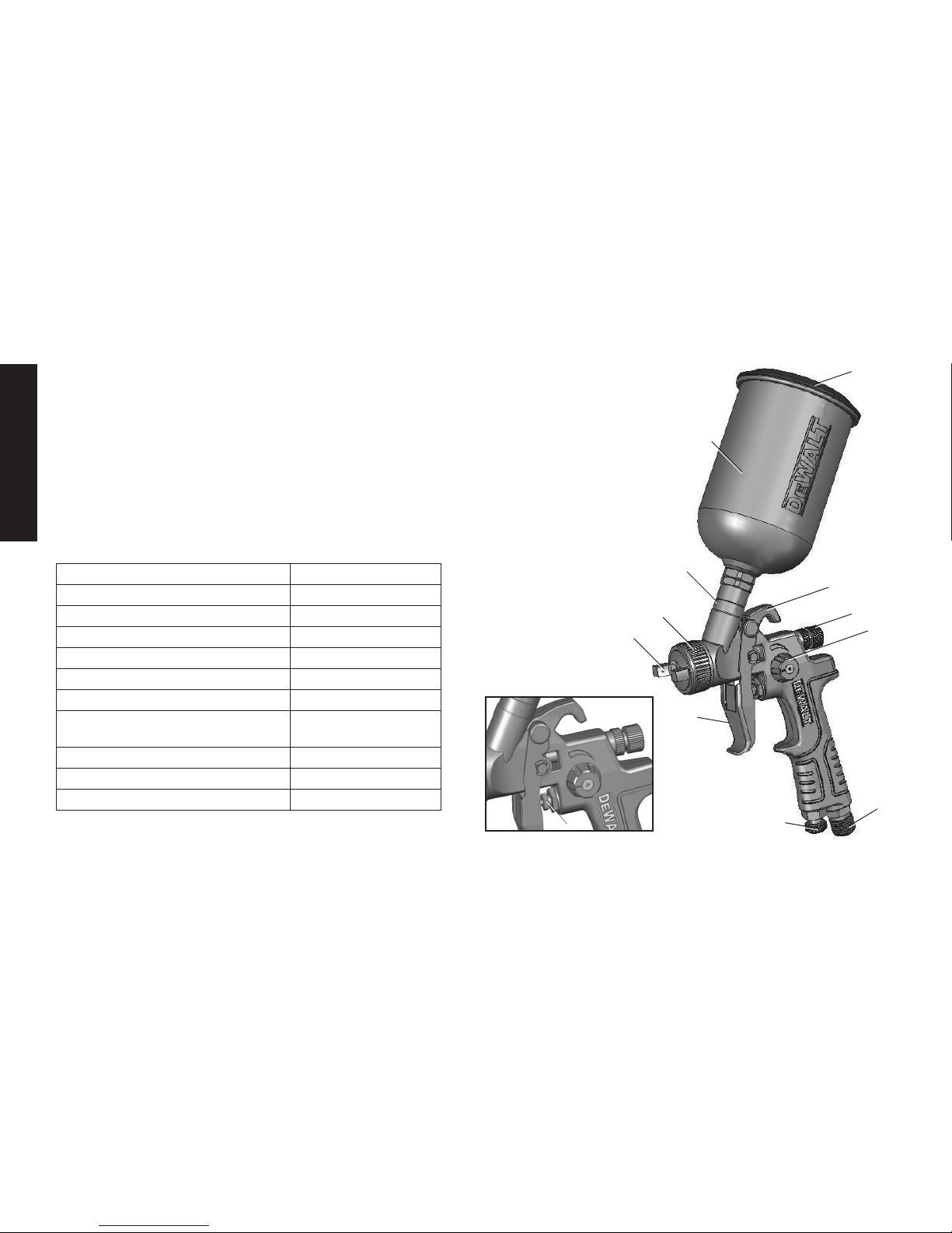
1. Loosen the air cap (C) and rotate the horns (D) to achieve
the desired spray pattern. Tighten the air cap.
2. Attach spray gun cup (A) to the gun handle.
NOTE: The (B) filter supplied is optional to protect against
contaminants and small particles. See parts list for
filter orientation.
CAUTION:
donotuselatexorotherheavypaints
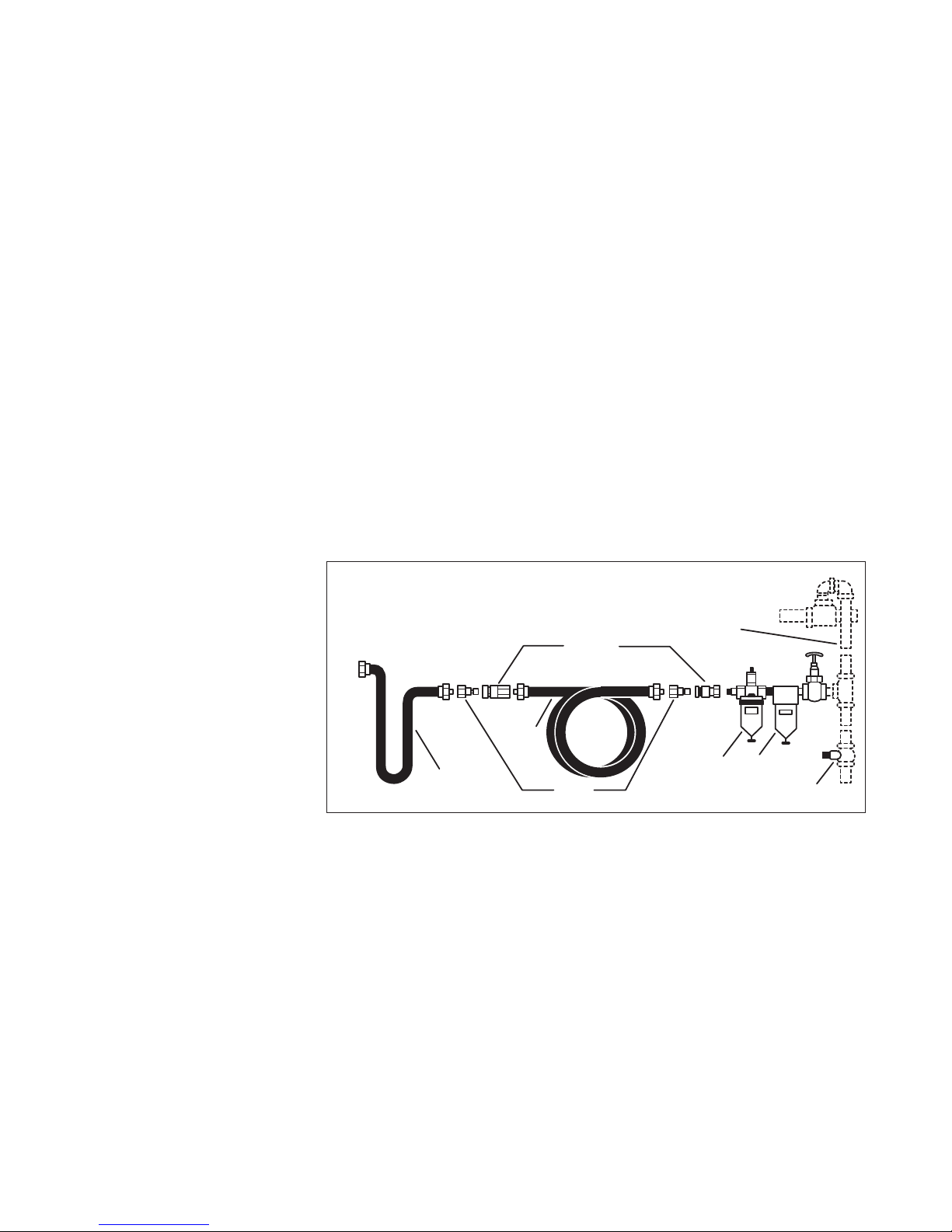
3. Attach air supply line to 1/4" NPS air inlet.
CAUTION:
NEVER point spray gun at self or any other person.
Accidentaldischargeofmaterialmayresultinseriousinjury.
4. Adjust air pressure on the air compressor.
CAUTION:
DONOTexceed60PSI.
5. Depress the spray gun trigger (E) fully to spray material.
NOTE: Depressing the trigger partially will cause only air
to be released.
ADJUST SPRAY GUN:
1. Turn the fluid control knob (I) counterclockwise to increase
the amount of material released, or clockwise to decrease.
2. Turn the pattern control knob (H) counterclockwise to
increase the width of the “fan spray”, or clockwise to decrease
the width of the spray.
3. Turn the air volume control knob (F) counterclockwise
to increase the air quantity, or clockwise to decrease
the air flow.
CAUTION: Care should be exercised when handling spray gun
to avoid damage to the orifice of the air cap and tip of fluid nozzle.
Damagetothesepartsresultsinirregularspraypatterns.
MAINTENANCE
WARNING: Shut off air compressor, release all pressure
by depressing trigger, and disconnect power source before
disassembly or removal of any part of the gun or attached
components.
CAUTION: Alwaysexerciseextremecarewhenusinganysolvent
orthinner.Nevercleanthegunnearfire,flame,oranysourceofheat
or sparks. Properly dispose of used cleaning materials.
CAUTION: DONOTsoaktheentiresprayguninsolventor
thinner for a long period of time as this will destroy lubricants
and possibly impair operation. NEVERuselyeorcausticalkaline
solution for cleaning. Such solutions will attack aluminum alloy
parts of the gun.

9
MAINTENANCE CONTINUED
It is important that the spray gun be cleaned after each use.
Cleaning
1. Empty material from gravity feed cup and replace with a
suitable solvent or thinner.
2. Operate trigger until all material traces have disappeared
and gun is thoroughly clean.
3. Clean air cap with a brush.
4. Wipe the exterior of the spray gun with a solvent soaked
cloth or use cleaning brush(es) provided to remove any
accumulated material.
IMPORTANT: Make certain that the air cap and fluid nozzle are
kept clean at all times. If necessary, remove these two components
and soak them in solvent. DO NOT use hard objects to clean
clogged holes. The smallest amount of damage may cause
irregular spray pattern.
NOTE: If the fluid nozzle is to be removed for thorough cleaning,
squeeze the trigger to prevent damage of the fluid needle tip when
unscrewing the nozzle.
Lubrication
Lubrication procedures must be observed after thoroughly cleaning the
gun to ensure effective, high quality performance of spray gun.
1. Lubricate working points with straight mineral oil, or castor oil.
2. Periodically, place a few drops of oil on tapered sections
of the fluid nozzle to ensure easy operation of the air cap.
When spraying water base materials, coat the fluid nozzle
inside and outside with straight mineral oil after each use.
3. Outer diameter of the needle sleeve in the fluid needle
assembly must be lubricated occasionally with straight mineral oil.

10
English
Defective Pattern Likely cause Suggested Remedy
1. Dirty or damaged
air cap
2. Dirty or damaged
fluid tip
1. Rotate air cap 180°. If the
pattern follows the air cap,
the problem is in the air cap.
Clean and inspect the air cap.
If the pattern is not corrected,
replacement is necessary.
2. If pattern doesn’t follow the air cap,
the problem is with the fluid tip.
Clean and inspect the tip for dried
paint, dirt or damage. If the pattern
is not corrected, replacement
is necessary.
Air pressure too high for
material viscosity being
sprayed.
1. Reduce air pressure.
2. Turn pattern control knob
clockwise to decrease fan width.
Turn fluid needle adjusting nut
counterclockwise to increase
fluid flow.
1. Dirty or distorted air
horn holes.
2. One of the air horn
holes completely
obstructed.
1. Rotate air cap 180°. If the
pattern follows the air cap,
the problem is in the air cap.
2. Clean and inspect the horn
holes. If the horn holes are
distorted, replacement is
necessary.
Air getting into paint
stream somewhere.
Example: Same
symptoms as a cup
running out paint.
1. Check and tighten fluid needle
packing nut.
2. Tighten fluid tip.
3. Check fluid tip seat for damage.
4. Check for poor gun to cup seating.
5. Check that cup is correctly
fastened on the gun.
Defective Pattern Likely cause Suggested Remedy
1. Fluid nozzle
cracked or worn
2. Leak at thread
of fluid nozzle
3. Leak at fluid needle
4. Needle packing
worn out
5. Insufficient fluid in cup
6. Vent hole in
container cover clogged
1. Tighten or replace
2. Tighten fluid nozzle
3. Tighten compression nut assembly
or replace needle packing
4. Replace packing
5. Fill cup with fluid
6. Clean out
Air back
pressuring
into cup.
Excessive air blowing
back into cup.
1. Tighten fluid tip.
2. Check fluid tip seat.
3. Check for damaged fluid seat
on tip or seat on gun head.
Unatomized
or spattered
spray
1. Material too heavy
2. Insufficient air
pressure
3. Fluid pressure
too high
4. Dried material on tip
of fluid nozzle or
air jets of air cap
1. Thin material or use larger orifice
fluid nozzle set
2. Increase pressure to within limit
3. Reduce pressure
4. Clean
Inadequate
air delivery 1. Air needle partially
closed
2. Dried material in air
jets or air cap
3. Obstruction in air line
1. Open control knob
2. Clean
3. Remove obstruction
Excessive fog 1. Air pressure too high
for viscosity of fluid 1. Reduce air pressure and/or
open fluid control knob
TROUBLESHOOTING GUIDE
This section provides a list of the more frequently encountered malfunctions, their cause and corrective actions. The operator or maintenance personnel can
perform some corrective actions, and others may require the assistance of a qualified D
e
WALT technician or your dealer.
Spitting, irregular
or fluttering spray
Heavy top or
bottom pattern
Split
pattern
Gun splitting

Defective Pattern Likely cause Suggested Remedy
Material leaking
from fluid inlet
of cup.
1. Loose cup or
foreign substances
on/ between cup
thread and fluid inlet
1. Tighten and clean
or replace it
Material leaking
from nozzle when
trigger is released
1. Worn fluid needle
2. Dried material in tip
of nozzle
3. Loose packing nut
1. Replace
2. Clean
3. Tighten needle
packing nut by turning
counterclockwise
A. Dried material is
clogging side-port “A”
and causing
side-port “B” to blow
spray towards the
clogged side
Soak side-ports in
thinner to clean clog.
DO NOT poke any
opening with hard objects.
B. 1. Dried material at
fluid nozzle “C”
restricts air flow
2. Loose air nozzle
3. Air pressure
set too high
1. Remove air nozzle.
Wipe off fluid tip using a
cloth soaked in thinner
or by soft brush
2. Fasten nozzle securely
3. Reduce air pressure
TROUBLESHOOTING GUIDE
This section provides a list of the more frequently encountered malfunctions, their cause and corrective actions. The operator or maintenance personnel can
perform some corrective actions, and others may require the assistance of a qualified D
e
WALT technician or your dealer.
A
B
C
View other Power Tools made by DeWalt Tools on our website.
Table of contents
Other DeWalt Paint Sprayer manuals
Popular Paint Sprayer manuals by other brands

Larson Electronics
Larson Electronics IND-MD-DF-ESF-R2-SP0017 instruction manual

Mytee
Mytee 6001 Electric Boss instructions

Smithco
Smithco SPRAY STAR 1002 with Raven 203 System manual

Gilson
Gilson Performer III SS-3 operating manual

Graco
Graco PROX19 owner's manual

Textron
Textron Jacobsen DS312 Assembly & operation manual

WALTHER PILOT
WALTHER PILOT Pilot III F operating instructions

Performance Tool
Performance Tool M578DB owner's manual

Earlex
Earlex Spray Port HV7000A operating instructions

Stern
Stern SG-800A operating instructions

Grizzly
Grizzly H7671 H7672 instruction manual

C.A. Technologies
C.A. Technologies Panther 200Z Product information