18
EngLIsH
Congratulations!
You have chosen a DeWALT tool. Years of experience, thorough product development and
innovation make DeWALT one of the most reliable partners for professional power toolusers.
Technical Data
D27300
Voltage VAC 230
Type 2
Power input W2100
Power output W1650
No-load speed max/min-1 6200
Feed speed m/min 5
Cutting height (max.) mm 160
Max. cutting width (max.) mm 260
Max. cutting depth
Planing mode mm 2.5
Thicknessing mode mm 3
Blade size mm 20
Weight kg 54
LPA (sound pressure) dB(A)* 96
KPA
(sound pressure uncertainty)
dB(A) 3
LWA
(sound power)
109
KWA
(sound power uncertainty)
dB(A) 3.1
* at the operator’s ear
nOTE (D27300 OnLY): This device is intended for the connection to a power supply system
with maximum permissible system impedance Zmax of 0.27 Ω at the interface point (power
service box) of user’ssupply.
The user has to ensure that this device is connected only to a power system which fulfils the
requirement above. If necessary, the user can ask the public power supply company for the
system impedance at the interfacepoint.
EC-Declaration of Conformity
Machinery Directive
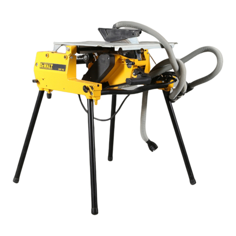
Thickness Planer
D27300
DeWALT declares that these products described under Technical Data are in compliance with:
2006/42/EC, EN61029-1:2009 + A11:2010, EN61029-2-3:2011.
These products also comply with Directive 2014/30/EU and 2011/65/EU. For more information,
please contact DeWALT at the following address or refer to the back of themanual.
The undersigned is responsible for compilation of the technical file and makes this declaration
on behalf ofDeWALT.
Markus Rompel
Vice President of Engineering, PTE-Europe
DeWALT, Richard-Klinger-Straße 11,
D-65510, Idstein, Germany
05.03.2019
WARNING: To reduce the risk of injury, read the instructionmanual.
Definitions: Safety Guidelines
The definitions below describe the level of severity for each signal word. Please read the
manual and pay attention to thesesymbols.
DANGER: Indicates an imminently hazardous situation which, if not avoided, will result
in death or seriousinjury.
WARNING: Indicates a potentially hazardous situation which, if not avoided, could result
in death or seriousinjury.
CAUTION: Indicates a potentially hazardous situation which, if not avoided, may result
in minor or moderateinjury.
NOTICE: Indicates a practice not related to personal injury which, if not avoided, may
result in propertydamage.
Denotes risk of electricshock.
English (original instructions)
THICKNESS PLANER
D27300
Denotes risk offire.
Safety Instructions
WARNING: When using electric tools basic safety precautions should always be followed
to reduce the risk of fire, electric shock and personal injury,
including thefollowing.
Read all these instructions before attempting to operate this product and save theseinstructions.
SAVE THIS MANUAL FOR FUTURE REFERENCE
General Safety Rules
1 . Keep work areaclear.
ʵ Cluttered areas and benches inviteinjuries.
2 . Consider work areaenvironment.
ʵ Do not expose the tool to rain. Do not use the tool in damp or wet conditions. Keep the
work area well lit (250–300 Lux). Do not use the tool where there is a risk of causing fire or
explosion, e.g., in the presence of flammable liquids andgases.
3 . Guard against electricshock.
ʵ Avoid body contact with earthed surfaces (e.g., pipes, radiators, cookers and refrigerators).
When using the tool under extreme conditions (e.g., high humidity, when metal swarf is
being produced, etc.), electric safety can be improved by inserting an isolating transformer
or a (FI) earth-leakage circuit-breaker.
4 . Keep other personsaway.
ʵ Do not let persons, especially children, not involved in the work, touch the tool or the
extension cord and keep them away from the workarea.
5 . Store idletools.
ʵ When not in use, tools must be stored in a dry place and locked up securely, out of reach
ofchildren.
6 . Do not force thetool.
ʵ It will do the job better and safer at the rate to which it wasintended.
7 . Use the righttool.
ʵ Do not force small tools to do the job of a heavy duty tool. Do not use tools for purposes
not intended; for example do not use circular saws to cut tree limbs orlogs.
8 . Dressproperly.
ʵ Do not wear loose clothing or jewellery, as these can be caught in moving parts. Non-skid
footwear is recommended when working outdoors. Wear protective hair covering to
contain longhair.
9 . Use protectiveequipment.
ʵ Always use safety glasses. Use a face or dust mask if working operations create dust or
flying particles. If these particles might be considerably hot, also wear a heat-resistant
apron. Wear ear protection at all times. Wear a safety helmet at alltimes.
10 . Connect dust extractionequipment.
ʵ If devices are provided for the connection of dust extraction and collecting equipment,
ensure these are connected and properlyused.
11 . Do not abuse thecord.
ʵ Never yank the cord to disconnect it from the socket. Keep the cord away from heat,
oil and sharp edges. Never carry the tool by itscord.
12 . Securework.
ʵ Where possible use clamps or a vice to hold the work. It is safer than using your hand and
it frees both hands to operate thetool.
13 . Do notoverreach.
ʵ Keep proper footing and balance at alltimes.
14 . Maintain tools withcare.
ʵ Keep cutting tools sharp and clean for better and safer performance. Follow instructions
for lubricating and changing accessories. Inspect tools periodically and if damaged have
them repaired by an authorized service facility. Keep handles and switches dry, clean and
free from oil andgrease.
15 . Disconnecttools.
ʵ When not in use, before servicing and when changing accessories such as blades, bits and
cutters, disconnect tools from the powersupply.
16 . Remove adjusting keys andwrenches.
ʵ Form the habit of checking to see that adjusting keys and wrenches are removed from the
tool before operating thetool.
17 . Avoid unintentionalstarting.
ʵ Do not carry the tool with a finger on the switch. Be sure that the tool is in the “off”
position before pluggingin.
18 . Use outdoor extensionleads.
ʵ Before use, inspect the extension cable and replace if damaged. When the tool is used
outdoors, use only extension cords intended for outdoor use and markedaccordingly.
19 . Stayalert.
