SPX 1717 User manual

Sheet No.
Issue Date: Rev. F, December 6, 2004
© SPX Corporation
16 501394 1Rod
17 501288 2 Caster
18 10236 2 Washer
19 10252 2 Lock Washer
(3/4")
20 10397 2 Hex Nut
(3/4")
21 501818 4 Spacer
22 501805 4 Bolt
23 501817 1 Press-in Grease Fitting
24 521591 1 Handle Stop
25 12101 1 Retaining Ring
(not shown)
516675 1
Pin/Retaining Ring Set
(not shown)
501234 1 Pump Roller
(not shown)
Form No. 107372
1 of 2
Parts List and
Operating Instructions
for: 1717
SPX Corporation
655 Eisenhower Drive
Owatonna, MN 55060-0995 USA
Phone: (507) 455-7000
Tech. Serv.: (800) 533-6127
Fax: (800) 955-8329
Order Entry: (800) 533-6127
Fax: (800) 283-8665
International Sales: (507) 455-7223
Fax: (507) 455-7063
Saddle Low Point: 3-3/4 in.
Saddle High Point: 22-1/2 in.
Lifting Range: 18-3/4 in.
Handle Length: 48 in.
Item Part
No. No. Qty. Description
1516574 1 Handle Ass’y
(not shown)
212368 1 Hex Hd. Cap Screw
(3/8-16)
3509167 1 U-joint
410549 1 Roll Pin
5519679 1 Hydraulic Unit
6518112 1 Decal
7529219 1 Saddle, Pad, & Retaining Ring
810472 1 Cotter Pin
9501401 1 Load Block
10 501800 2 Front Wheel
11 15953 2 Washer
(3/4")
12 14855 6 Retaining Ring
(3/4")
13 501814 1 Anchor Pin
(not shown)
14 513781 1 Spring
(not shown)
15 501803 2 Spacer
Two-Speed Service Jack
Max. Capacity: 2 Tons
Application: Designed to lift a wide range of motor vehicles.
Item Part
No. No. Qty. Description
1
24 25
6
7
23
3, 4
10
13, 14
12
11, 12
17
18
21, 22
19, 20
12, 15, 16
Shaded area reflects the last
revision made to this form.
8
9
25
Parts List & Operating Instructions Form No. 107372, Back of Sheet 1 of 2
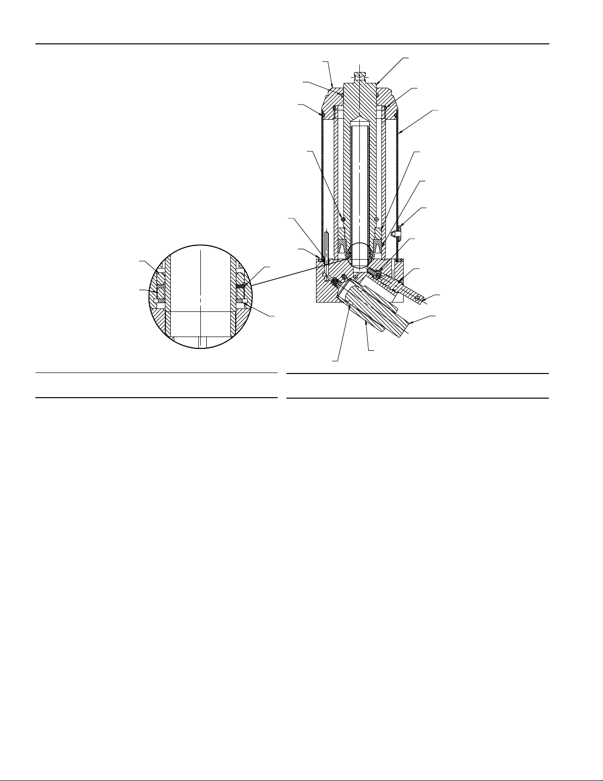
Item Part
No. No. Qty. Description
1517834 1 Rod
2j509129 1 O-ring
3512049 1 Reservoir Tube
4j516432 1 Brass Backup
5j509133 1 U-cup Seal
6j221278 1 Expansion Plug
8j12223 1 Steel Ball
9j501804 1 Ball Seat Screw
(torque to 130 in.•lbs.)
10 j10268 1 O-ring
11 j508931 1 Release Screw
12 512043 1 Pump Rod
13 512044 1 Tube Pump
(torque to 100 ft.•lbs.)
14 j513790 1 O-ring
15 j513791 1 Backup Washer
16 j509135 1 Seal
17 j501236 2 Filter Retainer
Bleeding Air from the System
Air can accumulate within a hydraulic system during shipment or if the automatic transmission fluid (ATF) supply runs too
low. This entrapped air causes the jack to respond slowly or feel “spongy.” The following procedure bleeds air from the
system.
1. Remove the jack from service, and place it on a level surface.
2. Open the release valve by turning the handle all the way counterclockwise (CCW).
3. Pump the handle six full strokes.
4. Close the release valve by turning the handle all the way clockwise (CW).
5. Pump the handle until the lift arm is fully extended.
6. Lower the lift arm by turning the handle all the way counterclockwise (CCW).
7. Test the jack for normal operation. If the lift pad doesn’t rise to the correct height, repeat Steps 2–6. If this doesn’t solve
the problem, call the OTC Technical Services Dept. at (800) 533-6127.
Item Part
No. No. Qty. Description
18 j221280 2 Screen Filter
19 201433 1 Retaining Ring
20 j509130 1 O-ring
21 j14739 1 O-ring
22 508822 1 Gland Nut
(torque to 100 ft.•lbs.)
23 j10658 1 O-ring
24 j517844 1 Support Ring
25 j517836 1 Backup Washer
26 j517837 1 Retaining Ring
16807 1 Button Hd. Cap Screw
(not shown)
513780 1 Compression Spring
(not shown)
514461 1 Round Grip
(not shown)
514462 1 Round Grip
(not shown)
208676 1 External Retaining Ring
(not shown)
512045 1 Spring Retainer
(not shown)
Parts marked with an asterisk (j) are included in Seal Kit No. 519675.
1
3
4
8, 9
11
2
12
13
5
10
17, 18
21
22
24
25
26
14, 15
16
19
6
20
23
No. 519679
Hydraulic Assembly

Sheet No.
Issue Date: Rev. F, December 6, 2004
© SPX Corporation
Parts List & Operating Instructions Form No. 107372
Safety Precautions
CAUTION: To prevent personal injury and damage to equipment,
•Read, understand, and follow all instructions, including ASME PALD Part 10 for service jacks.
If the operator cannot read these instructions, operating instructions and safety precautions
must be read and discussed in the operator’s native language.
•Before using the service jack to lift a vehicle, refer to the vehicle service manual to determine
recommended lifting surfaces on the vehicle chassis.
•Wear eye protection that meets ANSI Z87.1 and OSHA standards.
•Inspect the jack before each use; do not use the jack if it’s damaged, altered, or in poor
condition. Take corrective action if any of the following conditions are found: cracked or
damaged housing; excessive wear, bending, or other damage; leaking hydraulic fluid;
scored or damaged piston rod; loose hardware; modified or altered equipment.
•A load must never exceed the rated lifting capacity of the jack.
•Use the jack on a hard, level surface. The jack must be free to roll without any obstructions
while lifting or lowering the vehicle. The wheels of the vehicle must be in the straight-ahead
position and the hand brake released.
•Use the jack for lifting purposes only. Stay clear of a lifted load. Place support stands under
the axles before working on the vehicle.
•Center the load on the jack saddle. Off-center loads can damage seals and cause jack failure.
Lift only dead weight.
•Do not use blocks or other extenders between the saddle and the load being lifted.
•Do not modify the jack or use adapters unless approved or supplied by OTC.
•Lower the jack slowly and carefully while watching the position of the jack saddle.
•Use only automatic transmission fluid (ATF). The use of alcohol or hydraulic brake fluid could damage seals
and result in jack failure.
This guide cannot cover every situation, so always do the job with safety first.
Operating Instructions
Setup
1. Loosen the screw on the front of the handle socket.
2. Grease the socket opening. Insert the handle.
3. Torque the screw to 120 in. lbs.
Operation
1. Close the release valve by turning the handle clockwise (CW) as far as it will go.
2. Position the jack under the vehicle. IMPORTANT: Use the manufacturer’s recommended lifting points on the
chassis.
3. Pump the jack handle to raise the saddle to the contact point.
4. Check the placement of the jack; the load must be centered on the jack saddle. IMPORTANT: Avoid wheel
obstructions such as gravel, tools, or uneven expansion joints.
5. Finish lifting the vehicle by pumping the handle. Do not attempt to raise the jack beyond its travel stops.
6. Place approved support stands under the vehicle at points that will provide stable support. Before making repairs on
the vehicle, lower it onto the support stands by SLOWLY and CAREFULLY turning the handle counterclockwise (CCW).
2 of 2

Parts List & Operating Instructions Form No. 107372, Back of Sheet 2 of 2
Preventive Maintenance
IMPORTANT: The greatest single cause of failure in hydraulic units is dirt. Keep the service jack clean and well
lubricated to prevent foreign matter from entering the system. If the jack has been exposed to rain, snow, sand, or grit, it
must be cleaned before it is used.
1. Store the jack in a well-protected area where it will not be exposed to corrosive vapors, abrasive dust, or any other
harmful elements.
2. Regularly lubricate the moving parts in the wheels, arm, handle, and pump roller pin.
3. Replace the automatic transmission fluid (ATF) in the reservoir at least once per year. To check the ATF level, lower
the lift arm completely. Remove the rubber filler plug. The ATF level should be at the bottom of the filler plug hole. If
necessary, add ATF, and install the filler plug. IMPORTANT: The use of alcohol or hydraulic brake fluid could
damage the seals and result in jack failure.
4. Inspect the jack before each use. Take corrective action if any of the following problems are found:
a. cracked, damaged housing c. leaking hydraulic fluid e. loose hardware
b. excessive wear, bending, other damage d. scored, damaged piston rod f. modified equipment
5. Keep warning labels and instructional decals clean and readable. Use a mild soap solution to wash external surfaces
of the jack.
Troubleshooting Guide
Repair procedures must be performed in a dirt-free environment by qualified personnel who are familiar with this
equipment. CAUTION: All inspection, maintenance, and repair procedures must be performed when the jack is free
of a load (not in use).
Trouble Cause Solution
Jack does not lift
Jack lifts only partially
Jack advances slowly
Jack lifts load, but doesn't hold
Jack leaks ATF
Jack will not retract
Jack retracts slowly
1. Release valve is open.
2. Low/no ATF in reservoir.
3. Air-locked system.
4. Load is above capacity of jack.
5. Delivery valve and/or bypass valve not
working correctly.
6. Packing worn out or defective.
1. Close the release valve by turning the
handle all the way clockwise (CW).
2. Fill with automatic transmission fluid and
bleed system.
3. Bleed system. (See “Bleeding Air from
the system” on back of page 1.)
4. Use correct equipment.
5. Clean to remove dirt or foreign matter.
Replace ATF.
6. Replace packing.
1. Too much or not enough ATF.
1. Check
ATF
level.
1. Pump not working correctly.
2. Leaking seals.
1. Rework pump.
2. Replace seals. (Seal kit No. 519675 is
available from OTC.)
1. Cylinder packing is leaking.
2. Valve not working correctly (suction,
delivery, release, or bypass).
3. Air-locked system.
1. Replace packing.
2. Inspect valves. Replace if necessary.
3. Bleed system.
1. Worn or damaged seals.
1. Replace seals.
1. Release valve is closed.
1. Open the release valve by turning the
handle all the way counterclockwise
(CCW). May be necessary to clean
release valve.
1. Cylinder damaged internally.
2. Return spring(s) is damaged.
3. Link section is binding.
1. Send jack to OTC-authorized service
center. (Refer to OTC Form No. 104031.)
2. Replace return spring(s).
3. Lubricate link sections.
Other SPX Tools manuals


Popular Tools manuals by other brands

parktool
parktool BTS-1 manual

BLACKHAWK!
BLACKHAWK! ROKEN 1000K instruction manual

Traditional Tool Repair
Traditional Tool Repair DSA-116 Operation, parts and safety manual

Hellermann Tyton
Hellermann Tyton Overhead suspension CPK Assembly instructions

Band-it
Band-it S75099 quick start guide

Sel
Sel S 45 instruction manual

Power Fist
Power Fist 8505547 user manual

NetComm Wireless
NetComm Wireless AIMWLLR0-35 quick start guide

Power Fist
Power Fist 9166695 manual

Alto-Shaam
Alto-Shaam CS-100 Installation, operation and maintanance

Yard Works
Yard Works RHR-200 operating instructions

Lumberjack
Lumberjack PR5KIT Safety and operating manual


