Dewert 2000XL Series User manual

Dewert User Manual 2000XL Series–Updated 09.2021/2 MDR Page 1 of 20
User Manual
2000XL series model
Dear customer,
Congratulations on purchasing a product of outstanding quality.
Use of the best materials from renowned suppliers guarantees years of trouble-free operation, provided the
device is handled correctly and as intended in accordance with the conditions described in the user manual.
In the unlikely event you need to make a claim, please contact us.
We welcome suggestions from the users of our products.
Contents
1. Safety information....................................................................................................................................2
1.1 Applied symbols ..............................................................................................................................2
1.2 Applied standards............................................................................................................................2
1.3 Safety regulations............................................................................................................................2
1.4 Intended purpose.............................................................................................................................3
1.5 Information on setup and use.......................................................................................................... 3
1.6 Commissioning................................................................................................................................3
1.7 Safety notices .................................................................................................................................3
1.8 Model designation and type labelling..............................................................................................4
1.9 Meaning of the serial number..........................................................................................................4
2. Operating manual....................................................................................................................................5
2.1 Table design.................................................................................................................................... 5
2.2 Height adjustment............................................................................................................................ 5
2.3 Head part adjustment......................................................................................................................5
2.4 Adjustment of other sections........................................................................................................... 6
2.5 Movability (model dependent or optional) ....................................................................................... 6
2.6 Additional equipment.......................................................................................................................7
2.7 Echocardiography tables.................................................................................................................8
3. Additional accessories (for user-specific table configuration), in extracts................................................. 9
4. Technical data........................................................................................................................................... 10
4.1 Individual models of the 2000XL series.........................................................................................10
4.2 Technical data for electric motor................................................................................................... 13
4.3 Technical data for hydraulic system..............................................................................................14
5. Cleaning instructions.............................................................................................................................14
6. Maintenance and technical inspection ..................................................................................................15
7. Safety devices.......................................................................................................................................15
8. Reporting obligation...............................................................................................................................16
9. Disposal ................................................................................................................................................. 16
10. Declaration of Conformity ......................................................................................................................18
K.H. DEWERT GmbH
Vollmestr. 7
33649 Bielefeld
Germany
Tel. +49 / 521 400 27-0
Fax +49 / 521 400 27-27
info@khdewert.de
www.khdewert.de

Dewert User Manual 2000XL Series–Updated 09.2021/2 MDR Page 2 of 20
1. Safety information
1.1 Applied symbols
Safety instructions and key sections in these operating instructions are marked with the exclamation mark
symbol on the left. Please pay particular attention to these instructions and sections.
Symbols used on the device, depending on the respective equipment:
Observe instructions for use:
Risk of injury due to being pinched or crushed:
Caution, potential hazard:
Connection for potential equalisation according to DIN 42801:
1.2 Applied standards
This device has been designed and manufactured in accordance with national and international regulations.
This ensures a very high level of equipment safety.
The models described here comply with the following regulations and directives:
Regulation (EU) 2017/745
DIN EN IEC 60601-1
DIN EN ISO 14971
DIN EN 60601-2-52 partly based on
DIN EN IEC 62353
DIN EN ISO 10993-5/-10
DGUV Regulation 3
This device is a Class 1 medical device according to Regulation (EU) 2017/745 (MDR).
1.3 Safety regulations
This section contains a summary of the most important safety information:
Correct operation of the device is essential for safe operation. Therefore, please familiarise yourself with the
contents of these instructions for use before using the device. We recommend that you keep these
instructions for use near the device for future reference.
The device may only be used by authorised, instructed and competent persons who are sufficiently familiar
with its adjustment mechanism or have read and understood the operating manual fully. The manufacturer
cannot be held responsible for damage caused by or involving unauthorised persons. No third-party devices
may be installed without consultation with us or brought in the direction of movement of the table in such a
way that a possible hazard potential arises.
The user must ensure that the device is not accessible to unauthorised persons or cannot be operated by
unauthorised persons even when left unattended. When leaving the device, it should be secured in such a
way that unauthorised adjustment is impossible.
Keep a sufficient safety distance to the device during all adjustment procedures. Special attention
must be paid to the arms, hands, legs and feet of the user and the patient - RISK OF CRUSHING!
Make sure that there are no objects located directly around or underneath the device!

Dewert User Manual 2000XL Series–Updated 09.2021/2 MDR Page 3 of 20
1.4 Intended purpose
The table is used for the ideal positioning of patients for the purpose of curative and disease treatment,
examination, massage and health therapy.
Table operation and patient positioning on the table may only be performed by professionally trained persons
who have been instructed in its use or who, through experience with other similar medical devices, have
knowledge of its proper use, taking into account possible hazards.
Equipped with the options of movability (not wheel-lifting/fixing mechanism), side guards and push handle, the
intended purpose of the table is extended and also provides for the ideal positioning of patients for the
purpose of transport to pre-treatment or post-treatment locations. Patient positioning during the recovery
phase after a medical procedure is also permitted under supervision.
Otherwise, the device must only be moved within the room for cleaning or patient access.
This device has been developed exclusively for use indoors and in normal ambient conditions and can be
used in the following areas: laboratories, medical practices, examination and treatment rooms, hospitals,
clinics, physiotherapy practices, occupational therapy centres and doctors’ surgeries.
This table is not classed as surgical furniture and must, therefore, not be used for surgical purposes.
The expected service life is 10 years or 100,000 drive cycles (double stroke = 1x up and down).
1.5 Information on setup and use
When packed, the device may be exposed to the following environmental conditions for approx. 3 months:
Transport/Storage temperature: -20° to +50°C
Operating temperature: +10° to +40°C
Relative humidity: 30% to 75%
Air pressure: 800hPa to 1060hPa
When transporting the device in a vehicle, it must be secured properly against moving. To do so, lock the
castors (optional equipment) and ensure further safety measures.
When setting up the device, do not lift it at the head part, as this may damage the head part and/or the
release mechanism.
Hold and lift the table on the left and right-hand side of the underframe. The table must stand securely on its
feet or castors on a level, flat and solid surface. Before use, activate the brakes on the castors and make sure
they are working properly.
When transporting the table, take hold of the underframe, NOT the upper frame.
1.6 Commissioning
The device is ready for use upon delivery. Remove the power cable from the film packaging on the
underframe of the table and connect it properly to a permanently installed mains socket. When routing the
power cable, make sure the cable cannot be crushed, rolled over or otherwise damaged.
Lock the castors (optional) or the wheel system (optional). As the operator, carry out a thorough and precise
function check once the device has been set up. Prior to commissioning, clean the device and remove any
contamination from transport. Make sure that no connecting cables from the hand or foot switch to the motor
are trapped in the mechanism and thus damaged.
Operation in potentially explosive atmospheres is not permitted.
1.7 Safety notices
This table may only be used for its intended purpose. Any other use is strictly prohibited and possibly
dangerous. The manufacturer cannot be held responsible for damage caused by improper use. Patients may
only be positioned in preparation for treatment/examination by professionally trained persons.
Please note: This table is not classed as surgical furniture.
Prior to and when adjusting the height of the table, make sure that no persons or objects are located in the
adjustment range of the table and that nobody has their hands on the underframe.
The following basically applies: Never reach into or under the frame of the table when adjusting the height.
Height adjustment can result in injury if the user does not pay due care and attention. Therefore, take great
care when performing this procedure.

Dewert User Manual 2000XL Series–Updated 09.2021/2 MDR Page 4 of 20
When adjusting the upholstery parts, make sure that no persons or objects are in the adjustment range. Make
sure that no persons reach under the upholstery part or lean on the underframe.
Important for the user: When adjusting the upholstery parts, do not reach under the spacers located beneath
the upholstery parts.
Always use both hands when adjusting the lying surface elements: Use one hand to operate the adjustment
mechanism and the other hand for the lying surface adjustment.
The lying surfaces and the underframe are not anti-static as standard.
Our products are not intended for use in wet rooms and must under no circumstances be cleaned using so-
called bed washers. This would irreparably destroy the product.
The head part and armrests are only intended to support the patient and must not be used for sitting.
If the underframe is designed with movability (optional), all the castors must always be locked before using
the table.
Do not put a damaged device into operation.
Disconnect the device from the mains (power supply) in the event of a fault or during maintenance work. To
disconnect, be sure to grasp the plug, not the power cable.
This device must not be modified without the express permission of the manufacturer.
When transporting the table, take hold of the underframe, NOT the upper frame.
1.8 Model designation and type labelling
The exact model designation depends on the choice of frame colour:
-00 white powder coated (RAL 9010);
-03 white aluminium powder coated (RAL 9006);
-04 grey aluminium powder coated (RAL 9007)
and the type of selected height adjustment:
E = electromotive;
/H = hydraulic
The type plate is attached to the underframe on one long side of the table. It provides information about key
table data. The following symbols are listed there (by way of example), their meanings are:
Read the operating
manual
Serial no.
Applied part Type B
Caution, potential
hazard
Max. load
capacity
CE mark
Date of manufacture
Product may only
be used in dry
rooms
Do not dispose of with
household waste
Address of
manufacturer
Protective
insulation,
protection class II
1.9 Meaning of the serial number
The serial no. is located on the type plate or shown separately next to the type plate of the table. This number
is unique and firmly linked to this specific individual product. It enables us to identify this table model and
trace back assemblies/safety-relevant components at any time. Please always state this serial number when
enquiring about spare parts.

Dewert User Manual 2000XL Series–Updated 09.2021/2 MDR Page 5 of 20
2. Operating manual
2.1 Table design
When designing the table frames, special emphasis was placed on functional and operational safety. The
number of possible pinching points has thus been minimised, while remaining ones have been covered or
protected with spacers to prevent injury, thus ensuring safe and yet simple operation. Nevertheless,
necessary caution must always be exercised when using the table.
The table consists of the following assemblies: - underframe, - scissor section, - upper frame, - upholstery.
Depending on the respective version, these assemblies can feature further attachment parts. The surfaces of
the welded design are plastic coated. The height adjustment unit is located between the scissor section and
the underframe, which guarantees very high power transmission even in the lowest adjustment range (min.
height). By extending or retracting the lifting tube, the scissors are pushed apart or together, thus enabling
adjustment of the lying surface. The electrical adjustment system does not pose a hazard to the health and
safety of the user or the patient when used as intended. The lifting motor is activated by a low control voltage.
2.2 Height adjustment
Height adjustment (all models with electromotive height adjustment)
To adjust the height, the enclosed foot switch (optionally also hand switch) is operated according to the
marking. Beforehand, brief activation (double tap) must take place via the foot switch (or the hand switch).
Please refer to section 7. The table is lifted or lowered.
Height adjustment via foot switch rails (optional)
The electric motor for height adjustment is operated by a switch rail attached to the long side of the table,
which can be operated with your foot.
Press the switch rail down = the table is lifted
Lift the switch rail up = the table is lowered.
Here, too, brief activation (double tap) must take place beforehand (see section 7). Alternatively, the switch
rails can also be led out to the short side of the table. This facilitates height adjustment from the short sides of
the table.
The lifting motor is equipped with a freewheeling clutch as standard. This ensures automatic declutching if an
obstacle is encountered when lowering. In other words, the active tractive force of the motor no longer acts;
instead, simply the weight of the upper part of the table is applied. In the event of unforeseen entrapment, the
risk of injury is significantly reduced.
Note on operation
The electric motor is to be operated in intermittent duty mode. This means that a maximum duty cycle
of 25 s must not be exceeded. Before switching the motor back on, an interruption time of at least 400
s must be observed. If the maximum duty cycle is exceeded, an internal thermal switch (protective
temperature limiter) in the motor interrupts the power supply to the actuator. After the electric motor
has cooled down, the thermal switch automatically reconnects the power supply to the actuator.
Height adjustment (all models with hydraulic height adjustment)
At tables equipped with hydraulic height adjustment, the height is adjusted by repeatedly depressing
(pumping) the foot lever on one side of the table. To lower the table, the foot lever is simply lifted with your
foot. If the table is only lifted slightly each time the foot lever is depressed after transport or a longer period of
non-use, air bubbles have formed in the hydraulic system. To remove the air bubbles, pump the table
upwards under load and perform an additional 20 - 30 strokes of the pump when the table is in the uppermost
position. This will force air out of the system.
2.3 Head part adjustment
Despite the very robust and strong design of the gas spring, the head part must not be used for
sitting!
Head part adjustment using a gas spring
The head part is adjusted using a gas spring. To operate, press the release lever, which is located at the end
of the head part underneath the upholstery part, in the direction of the upholstered surface. The head part is

Dewert User Manual 2000XL Series–Updated 09.2021/2 MDR Page 6 of 20
lifted slowly to the positive end position. To lower, press down the head part and operate the release lever at
the same time. Once the desired position has been reached, let go of the release lever.
Head part adjustment using ratchets
Head part adjustment is enabled by two metal ratchets. Grasp the top of the head part in the centre and lift it
up to the desired inclination, the ratchets engage automatically. To lower the head part, lift it up as far as it will
go, the ratchets thus disengage. Subsequently lower the head part to the bottom end position.
Head part adjustment using a gas spring (models 2006XLE, 2006XL/H, 2007XLE, 2007XL/H)
The head part is adjusted using a gas spring. To operate, press the release lever in the direction of the
upholstery. The upholstery part is lifted slowly to the positive end position. To lower, press down the
upholstery part and operate the release lever at the same time. Once the desired position has been reached,
let go of the release lever. The strength of the gas spring ensures ease of adjustment despite the patient’s
weight. The corresponding upholstery part can also be folded down 90° on these models. To do so, press and
hold down the release lever and swivel the upholstery part until it is folded down.
Head part adjustment using an electric motor (optional)
The head part is adjusted using a separate electric motor. By operating the hand switch, the inclination of the
head part can be varied steplessly and adjusted according to your needs. Please observe section 7.
Depending on the respective design, the motor is equipped with a freewheeling device. As a result, the motor
declutches automatically if an obstacle is encountered.
Always observe: There must be no persons in the adjustment range of the head part.
2.4 Adjustment of other sections
Adjustment of the lying surface to the inclined position (Trendelenburg position) using a gas spring
Adjustment to the Trendelenburg position takes place using a gas spring. Grasp the push handle with your
hands. Then pull the release lever at the end of the foot part towards you. The lying surface (at the foot part)
is lifted slowly to the positive end position (= head down - feet up - inclined position). To lower, press down the
lying surface and operate the release lever at the same time. Once the desired position has been reached, let
go of the release lever. The strength of the gas spring ensures ease of adjustment to the inclined position
despite the patient’s weight. Consequently, when unloaded, more force is required to adjust the lying surface
horizontally again. Caution is advised, especially with infusions.
Adjustment of the lying surface to the inclined position (Trendelenburg position) using an electric
motor
The foot part is adjusted using a separate electric motor. By operating the hand switch, the inclination of the
foot part can be varied steplessly. Here, too, brief activation (double tap) via the hand switch must take place
beforehand (see section 7). Please note: The inclination adjustment of the foot part also influences the
inclination of the head part (as they are interconnected). With the head part in a negative position, at
maximum inclination and when lowering the table at the same time to the lowest position, attention must be
paid to the head part. Should the head part come into contact with the floor, the gas spring is automatically
triggered and the head part is lifted in the positive direction. This is for emergency use only and is associated
with noise. Always observe: There must be no persons in the adjustment range of the entire lying surface.
Caution is advised, especially with infusions.
Foot part adjustment using a gas spring
The foot part is adjusted using a gas spring. To operate, press the release lever at the end of the foot part in
the direction of the upholstery. The foot part is lifted slowly to the positive end position. To lower, press down
the foot part upholstery and operate the release lever at the same time. Once the desired position has been
reached, let go of the release lever. The strength of the gas spring ensures ease of adjustment despite the
patient’s weight. Consequently, when unloaded, more force is required to adjust the foot part horizontally
again.
2.5 Movability (model dependent or optional)
Individually lockable castors
The castors can be locked using the foot-operated brake on the castor housings. In this case, the castors can
neither be moved nor rotated. To release, operate the brake on each castor again.
Please note: Standard castors are not electrically conductive = optional equipment.

Dewert User Manual 2000XL Series–Updated 09.2021/2 MDR Page 7 of 20
You can recognise conductive castors via the respective marking = yellow dot on the side of the running
surface or a yellow ring.
With this movability option, access to the patient is improved during examination and treatment thanks to easy
positioning within the room. Transporting patients is not considered as intended use.
Central movability
By operating a lever (on the outside of the table feet), all four castors are activated simultaneously. The
following moving options exist:
Stage 1: The castors of the table are locked and can neither be moved nor rotated.
Stage 2: = centre position: The castors are released and can be moved and rotated, the table can be moved
in all directions.
Stage 3: Three castors are released (= can be moved and rotated). The fourth castor is locked and cannot be
rotated (directionally locked castor), i.e. the wheel rolls in a fixed position and helps to steer the table in the
intended direction.
Please note: Rotational movement is only prevented when the castor is swivelled parallel to the lying surface.
This then allows the table to be moved in a straight line without pulling off to the side.
Wheel-lifting/fixing mechanism
The wheel-lifting/fixing mechanism allows a combination between fixed and movable table. There are two twin
castors on each short side of the underframe and foot levers at each corner. The foot levers consist of two
ergonomically arranged counter holders. This way, the table can be lifted and lowered quietly with your foot.
The wheel-lifting/fixing mechanism is not controlled centrally; a foot lever must be operated on each short side
of the table in order to lower the table onto its feet or to place it on the castors. This option ensures the device
can be simply relocated; however, the device is not intended for transporting patients (ground clearance
(distance foot - ground) when moving the table is approx. 14 mm).
2.6 Additional equipment
Nose opening (optional equipment)
If a nose opening is upholstered in the head part as an optional equipment feature, the opening can be closed
with a cushion (optional). To open up the nose opening, reach under the head part when the table is standing
still and press the cushion out from the bottom upwards (a slight amount of pressure is required). To close it,
simply insert the cushion into the opening (a slight amount of pressure is required).
Paper roll holder (optional equipment)
The paper roll holder consists of a holding bar and angle mount brackets or retaining brackets. In addition to the
stainless steel bar, the paper roll holding bar consists of a spring-loaded stainless steel sleeve featuring a round
steel gripping disc at the end. To insert the holding bar, feed the guide cotter pin of the stainless steel bar into the
rear hole of the angle mount bracket/retaining bracket. Then push the sleeve with the gripping disc against the
spring force and feed the front guide cotter pin into the second hole. Then relieve the spring tension on the sleeve.
To release the paper roll holder, proceed in the same way.
Push handles (model dependent or optional)
Depending on the actual equipment, push handles are located either at the end of the head part or the foot part, or
on both sides. When moving the table, always use both hands on the push handles to push/pull the table.
Side guard (model dependent or optional):
Insertable side guard
To remove the side guard, undo the two black knurled screws underneath the upholstery and pull out the side
guard. To insert the side guard, place the two guide pins in the locating holes and push the side guard
forward up to the stop/upholstery. Tighten both knurled screws. Before using the side guard, make sure the
two knurled screws are tightened properly (proceed in the same way with the second side guard, if
applicable). When not in use, the side guard can also be inserted into the mount the other way round, i.e. with
the rail pointing downwards. Remember to fix the side guard in place by tightening the two knurled screws
even when not in use.
Please note: Never use the side guard as a push handle. It has not been designed for this purpose.
Foldable side guard
Folding down the side guard: Grasp the side guard with one hand in the middle of the guard frame at the top
(or with two hands on the left and right at the top). Pull up the side guard evenly, thereby extracting the two
guide pins from the guides. Subsequently turn the side guard outwards slightly and hold it loosely, allowing

Dewert User Manual 2000XL Series–Updated 09.2021/2 MDR Page 8 of 20
the side guard to fold down through its own weight. Allow the side guard to fold all the way down until it
engages automatically.
Please note: Due to the two guides and guide pins, a small amount of force is only necessary when releasing
the lock (= briefly removing the side guard guide pins). Do not pull or push when allowing the side guard to
fold down (hardly any force is required).
Folding up the side guard: Grasp the side guard with one hand in the middle of the guard frame at the end
facing downwards (or with two hands on the left and right at the top). Push the side guard upwards and
outwards slightly, thereby releasing the lock. Now hold the side guard loosely and fold it up until it engages.
Please note: Do not use the side guard as a push handle.
Laterally lowerable side guard
Operating the side guard:
Hold the centre of the rail of the side guard with one hand and release it by moving it
minimally sideways (either towards the head or foot part). At the same time, use your other hand to pull out
and turn the locking pin (red knob) located in the centre of the side guard underneath the upholstery frame.
Press down or pull up the side guard using the rail until the locking pin engages audibly. After the locking pin
has engaged, the side guard is secured in place. To check whether the
side guard has engaged properly, move it sideways on the rail (either towards the head or foot part). Only
limited movement should then be noticeable.
Always operate the side guard with the necessary caution. Never operate the side guard if the hands,
fingers, etc. of another person are located between the bars or on the mechanism of the side guard.
Risk of being crushed/pinched!!!
The laterally lowerable side guard is completely screwed in place. If the side guard becomes too loose or has
excessive lateral play over time due to use, it can be readjusted by tightening the screws. The moving parts of
the side guard should be re-lubricated slightly at regular intervals
(spray oil, e.g. Ballistol).
Side guard, lowerable, for side rail
This side guard can be placed and fixed on any side rail using a clamp. By loosening the toggle screw of the
clamp, the position and height of the inserted side guard can be shifted and adjusted respectively. Complete
lowering below the upholstery level can only be achieved if the guide points
in the direction of the upholstery when the side guard is inserted into the clamp.
Please note: Never use the side guard as a push handle. It has not been designed for this purpose.
2.7 Echocardiography tables
The table for echocardiography treatment has a cut-out on the left-hand side in the upholstered surface. It can
be closed with a cushion. The cushion can be pushed out from the bottom upwards (a slight amount of
pressure is required). To close the cut-out, first place the cushion in the rear of the cut-out and then press it
down into the upholstered surface (a slight amount of pressure is required). The lower side of the cut-out is
not parallel to the upper side. There is a visible slant. The position of the cushion in the cut-out is thus clearly
identifiable and there is no risk of it being accidentally pushed out.
Caution: Do not reach under the cushion or into the open cut-out during height adjustment. Always
remove instruments/equipment from the cut-out area before adjusting the height.
Potential equalisation connector
A potential equalisation connector according to DIN 42801 is attached to the long side of the underframe on
the left (side with the upholstery cut-out). This connection must be used if interference from electromagnetic
radiation can be seen on the monitors during the examination, which could falsify the measured values.
Despite compliance with the applicable EMC regulations, the use of highly sensitive examination equipment
can cause this minimal radiation to become visible. Only use connectors that comply with DIN. Through
additional wiring of the individual assemblies, there is conductive contact between them.
The potential equalisation connector is marked with the symbol .

Dewert User Manual 2000XL Series–Updated 09.2021/2 MDR Page 9 of 20
3. Additional accessories (for user-specific table configuration), in extracts
•Foldable side guard
•Laterally lowerable side guard
•Twin castors Ø 100 mm, centrally lockable, non-conductive or conductive
•Comfort twin castors Ø 125 mm, centrally lockable, non-conductive or conductive
•Comfort twin castors Ø 150 mm, centrally lockable, conductive
•Foot operating lever for central lock
•Wheel-lifting/fixing mechanism
•Comfort twin castors Ø 100 or 125 mm, individually lockable
•Paper roll holder for examination tables
•Paper roll holder for transport/recovery tables
•Side rails
•Fastening clamp for side rail
•Infusion pole for fastening clamp
•Armrest for side rail and fastening clamp
•Push handle, curved or straight
•Push bar
•Nose opening in the head part and cushion
•Head part adjustment using a gas spring
•Electromotive head part adjustment
•Elastic soft upholstery
•Medium soft upholstery
•Wall protection bumpers / impact protection
•Additional foot switch
•Additional hand switch
•Foot switch fixation on the underframe
•Foot switch rails, for adjusting the height, laterally or surround
Dewert User Manual 2000XL Series–Updated 09.2021/2 MDR Page 10 of 20
4. Technical data
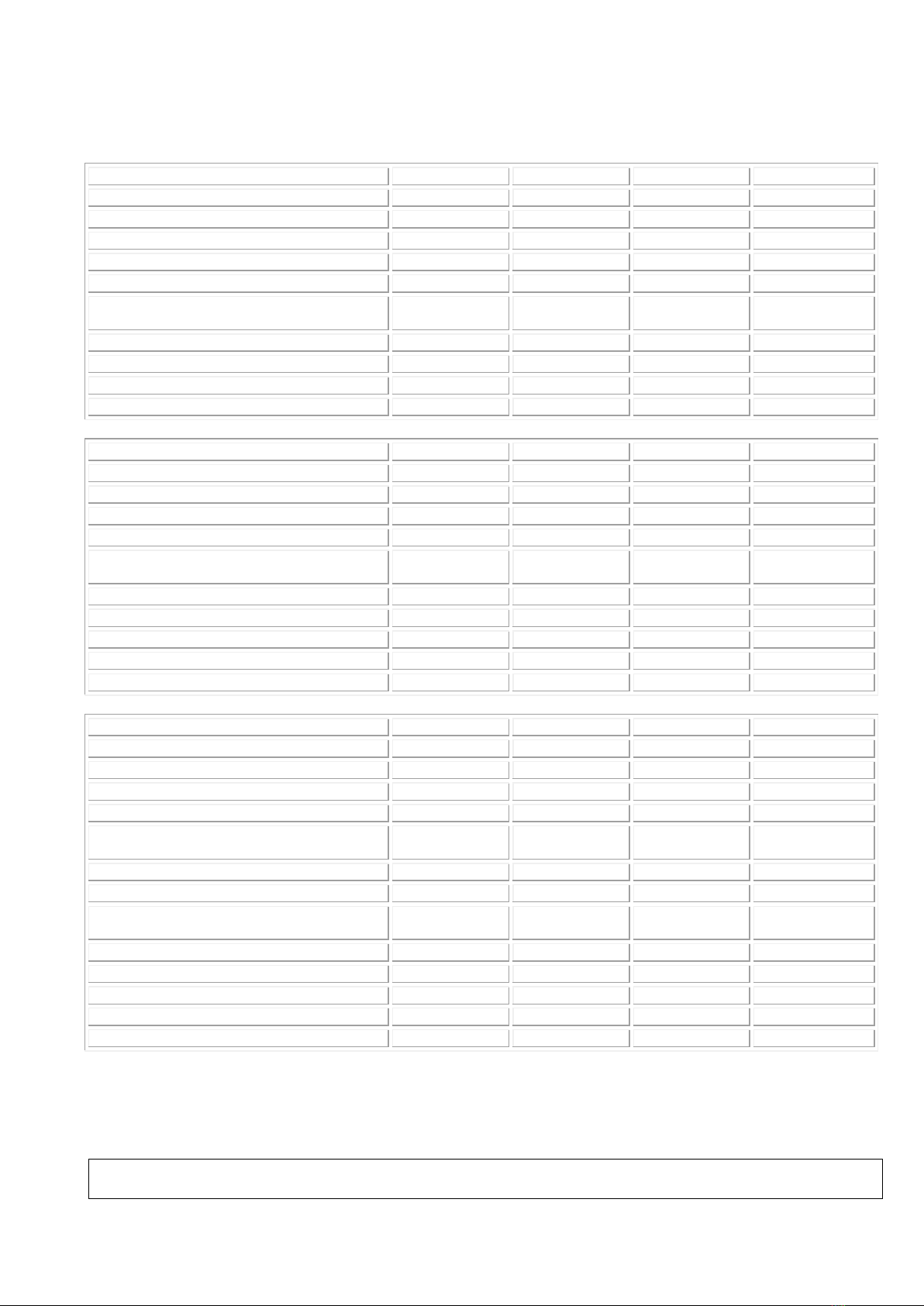
4.1 Individual models of the 2000XL series
Models
2000XLE
2000XL/H
2100XLE
2100XL/H
2001XLE
2001XL/H
2105XLE
2105XL/H
2110XLE
2110XL/H
Max. length (mm)
1950
1950
1400
1400
Width (mm)
700; 800
700; 800
650; 800; 1000
650; 800; 1000
Head part length (mm)
550
550
-
-
Weight (approx., depending on
equipment) kg
70; 75
70; 75
60; 70; 75
60; 70; 75
Min. –max. height (mm)
480 - 920
500 - 920
480 - 920
500 - 920
Adjustment time (motor) (s)
22
-
22
-
Head part adjustment range (gas spring)
-35° / +45°
-35° / +45°
-
-
Max. patient weight (kg)
280
250
250
250
Models
2600XLE **
2600XL/H **
2610XLE **
2610XL/H **
2605XLE **
2605XL/H **
2615XLE **
2615XL/H **
Max. length (mm)
1950
1950
1950
1950
Width (mm)
650; 800
650; 800
650; 800
650; 800
Head part length (mm)
570
570
570
570
Weight (approx., depending on
equipment) kg
75; 80
75; 80
75; 80
75; 80
Min. –max. height (mm)
500 - 940
520 - 940
500 - 940
520 - 940
Adjustment time (motor) (s)
22
-
22
-
Head part adjustment range (ratchets)
0° / +30°
0° / +30°
-
-
Head part adjustment range (gas spring)
0° / +45°
0° / +45°
-20° / +40°
-20° / + 40°
Max. patient weight (kg)
250
250
250
250
Models
2650XLE
2650XL/H
2655XLE
2655XL/H
2651XLE
2651XL/H
2656XLE
2656XL/H
Max. length (mm)
1950
1950
1950
1950
Width (mm)
650; 800
650; 800
650; 800
650; 800
Head part length (mm)
570
570
570
570
Weight (approx., depending on
equipment) kg
85; 90
85; 90
85; 90
85; 90
Min. –max. height (mm)
540 - 980
560 - 980
540 - 980
560 - 980
Adjustment time (motor) (s)
22
-
22
-
Adjustment time, inclined position (motor)
(s)
-
-
-
-
Head part adjustment range (ratchets)
0° / +30°
0° / +30°
-
-
Head part adjustment range (gas spring)
0° / +45°
0° / +45°
-20° / +40°
-20° / + 40°
Foot part adjustment range
0° / +25°
0° / +25°
0° / +25°
0° / +25°
Adjustment time, inclined position
-
-
-
-
Max. patient weight (kg)
250***
250***
250***
250***
The indicated table height may vary depending on the equipment, e.g.
- other castor sizes: Depending on the castor diameter
Dewert User Manual 2000XL Series–Updated 09.2021/2 MDR Page 11 of 20
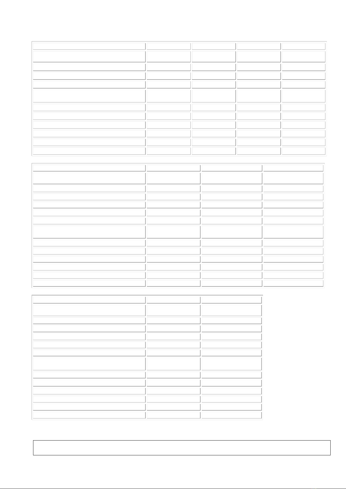
Models
2550XLE
2550XL/H
2552XLE
2552XL/H
2551XLE
2551XL/H
Width
optional: 800 mm
Width
optional: 800 mm
Max. length (mm)
1950
1950
1950
1950
Width (mm)
700; 800
700; 800
700; 800
700; 800
Head part length (mm)
800
800
800
800
Weight (approx., depending on
equipment) kg
85; 90
85; 90
85; 90
85; 90
Min. –max. height (mm)
500 - 940
520 - 940
540 - 980
560 - 980
Adjustment time (motor) (s)
22
-
22
-
Head part adjustment range (ratchets)
0° / +25°
0° / +25°
0°/ +25°
0°/ +25°
Head part adjustment range (gas spring)
0° / +40°
0° / +40°
0°/ +40°
0°/ +40°
Foot part adjustment range
/
/
0° / +30°
0° / +30°
Max. patient weight (kg)
250
250
250
250
Models
2210XL/H
2220XL/H
2250XL/H
Width
optional: 800 mm
Width
optional: 800 mm
Width
optional: 800 mm
Max. length (mm)
1950
1950
1950
Width (mm)
650; 800
650; 800
650; 800
Head part length (mm)
750
550
750
Overall length (mm)
2200
2200
2200
Overall width (mm)
800; 950
800; 950
800; 950
Weight (approx., depending on
equipment) kg
105
105
105
Min. –max. height (mm)
630 - 1050
570 - 990
630 - 1050
Head part adjustment range (ratchets)
-
0°/ + 30°
-
Head part adjustment range (gas spring)
0°/ +75°
0°/ +60°
0°/ +75°
Foot part adjustment range
-
-
0°/ +35°
Adjustment time, inclined position
-
-
-
Max. patient weight (kg)
250
250
250
Models
2310XL/H
2320XL/H
Width
optional: 800 mm
Width
optional: 800 mm
Max. length (mm)
1950
1950
Width (mm)
650; 800
650; 800
Head part length (mm)
750
550
Overall length (mm)
2200
2200
Overall width (mm)
800; 950
800; 950
Weight (approx., depending on
equipment) kg
125;135
125;135
Min. –max. height (mm)
570 - 990
640 - 1060
Head part adjustment range (ratchets)
-
-
Head part adjustment range (gas spring)
0°/ +75°
0°/ + 60°
Foot part adjustment range
-
-
Adjustment time, inclined position
0°/ +12°
0°/ +12°
Max. patient weight (kg)
250
250
The indicated table height may vary depending on the equipment, e.g.
- other castor sizes: Depending on the castor diameter

Dewert User Manual 2000XL Series–Updated 09.2021/2 MDR Page 12 of 20
Models
2150XLE
2150XL/H
2052XLE
2052XL/H
2155XLE
2155XL/H
2053XLE
2053XL/H
Max. length (mm)
1950
1950
2000
2000
Width (mm)
650; 800
650; 800
700; 800
700; 800
Head part length (mm)
750
750
500
500
Weight (approx., depending on
equipment) kg
80
80
95
95
Min. –max. height (mm)
500 - 940
520 - 940
540 - 980
550 - 970
Adjustment time (motor) (s)
22
-
22
-
Adjustment time, inclined position (motor)
(s)
-
-
21
-
Head part adjustment range (gas spring)
0° / +75°
0° / +75°
-20° / +45°
-35° / + 40°
Adjustment time, inclined position
-
-
0° / -22°
0° / -12°
Max. patient weight (kg)
250
250
250
250
Models
2006XLE
2006XL/H
2008XLE
2008XL/H
2007XLE
2007XL/H
2009XLE
2009XL/H
Max. length (mm)
1950/1550*
1950/1550*
2190/1790*
2190/1790*
Width (mm)
700; 800
700; 800
700; 800
700; 800
Head and foot part length (mm)
450
450
450
450
Weight (approx., depending on
equipment) kg
75
75
80
80
Min. –max. height (mm)
520 - 960
540 - 960
520 - 960
540 - 960
Adjustment time (motor) (s)
22
-
22
-
Head part adjustment range (gas spring)
-90° / +30°
-90° / +30°
-40° / +55°
-40° / + 55°
Foot part adjustment range
-
-
-90° / +30°
-90° / +30°
Max. patient weight (kg)
250***
250***
250***
250***
Models
2010XLE
2010XL/H
2114XLE
2114XL/H
2011XLE
2011XL/H
2115XLE
2115XL/H
Max. length (mm)
1950/1550*
1950/1550*
1400
1400
Width (mm)
700; 800
700; 800
650; 800
650; 800
Head and foot part length (mm)
450
450
-
-
Weight (approx., depending on
equipment) kg
75
75
75
75
Min. –max. height (mm)
530 - 970
550 - 970
480 - 920
500 - 920
Adjustment time (motor) (s)
22
-
22
-
Head part adjustment range (gas spring)
0° / +60°
0° / +60°
-
-
Foot part adjustment range
-90° / + 30°
-90° / +30°
-
-
Max. patient weight (kg)
250***
250***
250
250
The indicated table height may vary depending on the equipment, e.g.
- other castor sizes: Depending on the castor diameter

Dewert User Manual 2000XL Series–Updated 09.2021/2 MDR Page 13 of 20
2030XLE
2030XL/H
Models
2035XLE
2035XL/H
Max. length (mm)
1950
1950
Width (mm)
700; 800
700; 800
Head part length (mm)
750
750
Weight (approx., depending on
equipment) kg
75; 80
75; 80
Min. –max. height (mm)
480 - 920
500 - 920
Adjustment time (motor) (s)
22
-
Head part adjustment range (gas spring)
-25° / +70°
-25° / +70°
Max. patient weight (kg)
250
250
The indicated table height may vary depending on the equipment, e.g.
castors with 100 mm diameter - individually or centrally lockable - height: +20 mm
With other castor sizes, depending on the castor diameter
* Foot/head part in horizontal/vertical position
** With version -01 (chrome plated upper frame) height adjustment range: +20 mm
*** Weight load not on head and foot part, only centrally on the fixed lying surface
The motor is equipped with a thermal protective switch as standard. This causes the motor to cut out if the weight
load is too extreme or the motor’s duty cycle (DC: 25 s/400 s) is exceeded. The table should be ready for use again
after a 15-minute rest period. There is, therefore, no risk of overloading the motor.
The mechanics of the tables have been designed with extensive safety margins in mind. The max. patient weight
is provided with a 4-fold static safety factor, i.e. the design has been fully tested for a 4-fold load.
Technical data subject to change.
4.2 Technical data for electric motor
Manufacturer: Hanning Elektro-Werke GmbH & Co, D-33813 Oerlinghausen
Type of motor: SL 95
Type of actuator: Brushless asynchronous industrial motor
Mode of operation: Electromechanical linear motor with maintenance-free lifetime lubrication
Intermittent duty –installed thermal switch
Electronic activation with internal supply for the control element
Duty cycle (DC): 25 s / 400 s
i.e. move the table for max. 25 seconds under nominal load, then observe
a break of at least 400 seconds.
Nominal voltage: 220 –240 V, 1-50/60 Hz
Nominal consumption: Depending on the version 850W
For model 2052XLE/2053XLE: 1700W
Current consumption: Depending on the version 3.7A
For model 2052XLE/2053XLE: 5.0A
Protection class: II (protective insulation), connecting cable without protective conductor
Protection rating: IP X4 –resistant to water splashes,
Degree of protection: B
The motor is maintenance free.
When operated with sinusoidal alternating voltage, the motors used do not cause field or line-borne interference
within the meaning of EN 50081, Part 1 and 2, nor can their function be impaired by electromagnetic influences
within the meaning of EN 50082, Part 1 and 2.
* Model 2052XLE/2053XLE is equipped with a second electric motor. Both motors are connected to the mains by
a power cable.

Dewert User Manual 2000XL Series–Updated 09.2021/2 MDR Page 14 of 20
4.3 Technical data for hydraulic system
Manufacturer: Power-Packer Europa B.V., NL-7575 AT Oldenzaal
Type: Compact MK5 long
Mode of operation: Hydraulic cylinder with pump
The hydraulic unit is maintenance free.
5. Cleaning instructions
Upholstery covering
There are two different collections of upholstery covering to choose from:
•Skai Pandoria Plus (manufactured by Hornschuch/Continental in Germany)
•Skai Toronto EN (manufactured by Hornschuch/Continental in Germany)
For cleaning and disinfection, a selection of agents from various manufacturers has been tested for
compatibility. Please refer to the separate enclosed sheet.
The table is equipped as standard with the Dewert hygiene standards, which enable optimal cleaning and
disinfection:
•Depending on the model: Hinge lids are made of the identical upholstery covering
•All undersides of the upholstery parts are coated with an upholstery covering and can thus be cleaned
and disinfected
•Vent holes underneath the upholstery:
For the homogeneous foam to recover quickly, a rapid exchange of air is necessary. To ensure this, there
are individual vent points on the underside of the upholstery, which are hygienically sealed with special air
compensation caps that assume a valve function.
•Easy hygiene due to an open design
•Optional: Upholstery covering Skai Toronto EN with staynu
Table frame cleaning
The plastic-coated table frame and the chrome-plated bars and levers can be cleaned with mild household
cleaners, if necessary.
Do not use aggressive, abrasive or corrosive agents. Heavily soiled chrome-plated parts can be cleaned with
a chrome polish (e.g. Sidol). After cleaning, dry the frame with a soft dry cloth. Seal deep scratches and worn
areas with suitable repair agents to prevent moisture penetration.
Important:
At tables with hydraulic height adjustment as well as for the gas springs, wipe the piston rod with a soft cloth
at regular intervals. This prevents dust from entering through the dust lip and preserves the service life of the
unit.
Please note:
When cleaning, secure the table against unintentional lowering of the lying surface.
To do so, set all the adjustable sections to the horizontal position.
At tables with electromotive height adjustment, disconnect the power plug from the mains socket
beforehand.
At tables with hydraulic height adjustment, block the foot levers.
The power plug must not come into contact with water or cleaning agents.
The electrical components must not display any external damage through which liquid could enter. Do not
clean the table with water jets, a high-pressure cleaner or with a so-called bed washer. Only use moist cloths.
Dewert User Manual 2000XL Series–Updated 09.2021/2 MDR Page 15 of 20
6. Maintenance and technical inspection
The device has been designed and manufactured in such a way that it will operate safely over a very long
period of time if used as intended and in a correct manner. Depending on the conditions of use, place of use
and care, the expected operating service life is up to 10 years or 100,000 drive cycles (double stroke = 1x up
and down).
Regular maintenance procedures are required to ensure patient, user and product safety. They must be
carried out every two years at the latest. The maintenance procedures can be carried out by qualified
personnel/instructed personnel.
The scope of maintenance includes, for example:
•Thorough visual inspection of all components, especially motor and switch with mains supply line or
hydraulic system
•Function check
•Check all swivel joints for completeness
•Check proper fit of the screw connections
•Lubricate the swivel joints and operating levers slightly with low viscosity spray oil, if necessary
•Lubricate the roller guides with a little bearing grease or similar using a brush, if necessary
Insufficient lubrication is noticeable through noise development.
A checklist for maintenance/technical inspection can be found in the appendix.
In addition to maintenance in accordance with the legal requirements of DGUV Regulation 3 / IEC
62353, a technical inspection must be carried out every two years at the latest on tables with
electromotive adjustment. This technical inspection may only be carried out by authorised and
trained specialists.
A checklist for maintenance/technical inspection can be found in the appendix.
Despite regular maintenance/technical inspection, the user is also responsible for patient safety and proper
and reliable functioning. As the user, make sure that the table is in good working order prior to each use
(visual inspection). In the event of any abnormalities and unusual noise, take the table out of service
immediately and inform the operator.
Replace damaged or worn components immediately and do not use the table until it has been repaired.
The table complies with the safety regulations prescribed at the time it was placed on the market. Improper
repairs and structural modifications (disassembly of original parts, installation of third-party parts, etc.) may
result in hazards for patients and users. In the event of uncoordinated modifications to the table, the
Declaration of Conformity loses its validity and the warranty shall become null and void. We cannot be held
liable for damages resulting from uncoordinated modifications.
Only original Dewert spare parts may be used.
Risk of electrocution!
Work on the electrical system may only be carried out by qualified and authorised personnel in
compliance with all relevant provisions and safety regulations!
Foot and hand switches for adjusting the electric motor as well as gas springs are wearing parts whose
function may be impaired over the years depending on the frequency of use. Both can be replaced without too
much effort. Please request the corresponding installation diagram, if required. Replacement parts can be
obtained directly from Dewert.
7. Safety devices
Tables with electromotive adjustment must have an automatic device to deactivate the control elements when
moving the table. Reactivation of the control elements must be designed in such a way that they cannot be
triggered accidentally by patients, users or third parties.

Dewert User Manual 2000XL Series–Updated 09.2021/2 MDR Page 16 of 20
The actuator of this table is equipped with an integrated safety device to protect against
unauthorised/unintentional operation. This device goes into “sleep mode” 3 seconds after the last operation
and can only be reactivated with a defined switching sequence, the so-called double tap.
To “wake up” the actuator or the control unit, first press the desired direction of travel for approx. 1 second on
the control element. After a short waiting time (1-2 seconds), press the desired direction of travel again and
the actuator can be moved for a maximum of 30 seconds in this direction of travel.If the switching cycle of the
double-tap function is not observed, the actuator cannot be operated. After 30 seconds of operation in one
direction of travel, the actuator switches off and goes into sleep mode. The actuator can still be operated for
up to 3 seconds after the last operation to ensure fine adjustment. Within this time window, it is possible to
move in each direction of travel again for a maximum of 30 seconds. The actuator always goes into “sleep
mode” automatically 3 seconds after the last operation.
The motor is equipped with a safety freewheeling clutch as standard:
When lowering, the motor declutches automatically if an obstacle is encountered, and the flow of power is
interrupted. In other words, the active tractive force of the motor no longer acts; instead, simply the weight of
the upper part of the table is applied. In the event of unforeseen entrapment, the risk of injury is significantly
limited.
In addition, the table can be equipped with another option:
Foot switch cover
The top of the foot switch is fitted with a protective cover. This makes unintentional or unauthorised operation
more difficult.
8. Reporting obligation
All serious incidents occurring in connection with the product shall be reported to the manufacturer (K.H.
Dewert GmbH) and to the competent authority of the Member State in which the user and/or the patient
resides.
Member State
Competent authority
Web
Estonia
Health Board
Terviseamet
https://www.terviseamet.ee/en
Finland
Fimea
https://www.fimea.fi/web/en
Iceland
Iceland Medicines
Agency
https://www.ima.is/
Luxembourg
CNS
https://cns.public.lu/en
Malta
MCCAA
https://mccaa.org.mt/
Switzerland
Swiss medic
https://www.swissmedic.ch/swissmedic/de/home.html
A serious incident is an incident that directly or indirectly had, could have had, or may have had any of the
following consequences:
•death of a patient, user or other person,
•temporary or permanent serious deterioration of the state of health of a patient, user or other person,
•serious threat to public health.
9. Disposal
•Packaging
Safety notice: Pay attention to sharp edges and pointed objects during disposal!
The packaging materials produced are mainly:
oCardboard/Paper
oPlastic

Dewert User Manual 2000XL Series–Updated 09.2021/2 MDR Page 17 of 20
oWood (when delivered on a pallet)
Please observe the local regulations for waste disposal and preferably recycle the materials.
As a manufacturer, we are licensed as a participant in the Dual System in accordance with the German
Packaging Act (VerpackG) and therefore bear the disposal costs, meaning you can dispose of the packaging
free of charge.
•Product
Safety notices:
oPay attention to sharp edges and pointed objects!
oWhen transporting the table, only take hold of the underframe, NOT the upper frame.
oIn order to prevent accidents later on, the no longer used product must be rendered unusable
immediately, e.g. by disconnecting the power cable.
Please observe the local regulations for waste disposal and preferably recycle the materials.
Tables with electromotive height adjustment are subject to WEEE Directive 2012/19/EU. These old devices
must be collected, recycled and disposed of in an environmentally sound manner. Use the return and
collection systems available to you for this purpose.

Dewert User Manual 2000XL Series–Updated 09.2021/2 MDR Page 18 of 20
10. Declaration of Conformity
EU Declaration of Conformity for medical devices
Manufacturer: K.H. DEWERT GmbH
Vollmestr. 7
D-33649 Bielefeld
The product: Height adjustable table
Model designation:
2000XLE, 2000XL/H, 2001XLE, 2001XL/H, 2006XLE, 2006XL/H, 2007XLE, 2007XL/H, 2008XLE,
2008XL/H, 2009XLE, 2009XL/H, 2010XLE, 2010XL/H, 2011XLE, 2011XL/H, 2030XLE, 2030XL/H,
2035XLE, 2035XL/H, 2600XLE, 2600XL/H, 2605XLE, 2605XL/H, 2610XLE, 2610XL/H, 2615XLE,
2615XL/H, 2650XLE, 2650XL/H, 2651XLE, 2651XL/H, 2655XLE, 2655XL/H, 2656XLE, 2656XL/H,
2100XLE, 2100XL/H, 2105XLE, 2105XL/H, 2110XLE, 2110XL/H, 2114XLE, 2114XL/H, 2115XLE,
2115XL/H, 2150XLE, 2150XL/H, 2155XLE, 2155XL/H, 2052XLE, 2052XL/H, 2053XLE, 2053XL/H
2550XLE, 2550XL/H, 2551XLE, 2551XL/H, 2552XLE, 2552XL/H, 2210XL/H, 2220XL/H, 2250XL/H,
2310XL/H, 2320XL/H
The numerical codes -00, -03, -04 appended to the individual model designation only indicate the colour of the frame
(-00 = white frame, -03= white aluminium frame, -04= grey aluminium frame).
Basic UDI-DI: 4063907KHDewertLiegenP2
SRN: DE-MF-000005967
Intended purpose:
The table is used for the ideal positioning of patients for the purpose of curative and disease treatment,
examination, massage and health therapy.
Table operation and patient positioning on the table may only be performed by professionally trained persons
who have been instructed in its use or who, through experience with other similar medical devices, have
knowledge of its proper use, taking into account possible hazards. Equipped with the options of movability
(not wheel-lifting/fixing mechanism), side guards and push handle, the intended purpose of the table is
extended and also provides for the ideal positioning of patients for the purpose of transport to pre-treatment or
post-treatment locations. Patient positioning during the recovery phase after a medical procedure is also
permitted under supervision. Otherwise, the device must only be moved within the room for cleaning or
patient access. This device has been developed exclusively for use indoors and in normal ambient conditions
and can be used in the following areas: laboratories, medical practices, examination and treatment rooms,
hospitals, clinics, physiotherapy practices, occupational therapy centres and doctors’ surgeries.
This table is not classed as surgical furniture and must, therefore, not be used for surgical purposes.
complies with the relevant provisions of Regulation (EU) 2017/745, Article 19, Annex IV (Class 1
according to Annex VIII, Chapter III, No. 4.1 of 5 April 2017).
We hereby declare conformity with the aforesaid directive.
As the manufacturer, we bear sole responsibility for issuing this EU Declaration of Conformity.
Mark:
Bielefeld/Germany, 01 September 2021
K.-H. DEWERT GmbH
Management

Checklist for maintenance/technical inspection
to IEC 62353 and DGUV Regulation 3
Device
Model designation
Serial no.
Location
Responsible person
Date, inspector
Actuator designation
Inspections OK FAIL Description of defects
Visual inspection
Overall impression of the table OK?
Labels, CE mark, type plate present?
Manufacturer’s operating manual available and accessible?
Sufficient space available when carrying out all adjustment functions?
Mechanical structure undamaged:
Welds without obvious damage?
Screw connections correct and complete?
Upholstery undamaged?
Upholstery attachment correct?
All mechanical elements intact and complete?
Electrical system and power cable undamaged?
All switches and supply lines undamaged?
Function check
With electromotive adjustment:
Move all motors with the foot switch or the hand switch to both limit positions until automatic switch-off to ensure that:
* the table operates smoothly without any collisions or blockages
* no cable/connection can be overstretched, crushed or otherwise damaged
* the motors run without noticeable noise development
* the end position switch-off of the actuators works properly
Foot switch / hand switch / foot switch rails work(s) without interference
Power cables and power plugs undamaged?
Correct and safe routing of the power cable and connection?
Checking the safety device:
Double-tap function and freewheeling motor, function given?
With hydraulic height adjustment:
Function given?
Check by operating the pedals until the table reaches the uppermost position
Continue to operate the pedals approx. 5-10 times (any air is pressed out of the system)
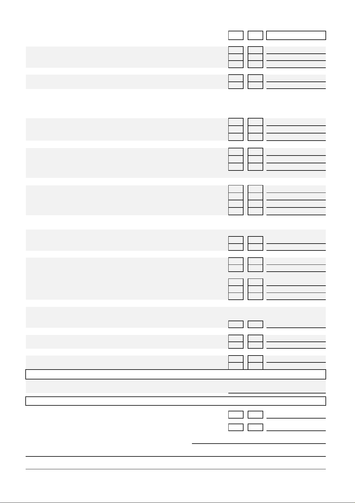
OK FAIL Description of defects
Height retained?
Hydraulic pump leaking?
Smooth lowering possible?
Check by operating the pedals to lower the table
Strong noise development?
Wipe the piston rod with a cloth
Lying surface adjustment functions:
Metal ratchets - arrester - gas spring
Metal ratchet inspection: Lifting the lying surface segment:
Do the two metal ratchets engage properly and securely?
Do they engage evenly?
Is this ensured in every adjustment position?
Arrester inspection: Lifting the lying surface segment:
Is the segment held properly and securely at every height?
Perform the test also with a load
Is the function smooth without clamping?
(= move the lying surface segment without fixing the clamping lever)
Gas spring inspection: Lifting the lying surface segment:
Does the gas spring respond when released?
Is the segment held properly and securely at every height?
Is the piston rod of the gas spring free of grease and not leaking?
Clean the piston rod with a cloth
Accessories:
Accessories such as belts, belt pads, belt guides, paper roll holders,
armrests, etc. undamaged, and is proper and secure fixing/function possible?
All necessary toggle screws present?
Possible movability:
Castors undamaged, freewheeling given?
Connection to frame undamaged?
Re-tighten all screw connections (with central locking system,
also the grub screws of switch levers)
Safe braking effect?
Check with locked brakes by pulling and pushing the table
Structural inspection:
Checking the scissor fittings:
Use a wrench to check the six fixing screws of the scissors (remove the black caps for this purpose)
and the hexagon socket head screws for a very tight fit
Checking the side guard:
Easy adjustment possible without clamping?
Proper locking during setup/lowering?
Laterally lowerable side guard:
No adjustment possible without pulling the locking knob?
Proper engagement in the end positions?
Electrical testing
Leakage current measurement (protection class II, degree of protection B)
(max. 0.1 mA permissible) Measured value:
Final assessment
Everything error free?
Device put out of operation until it has been repaired?
Comments
Place / Date / Signature of inspector
Next inspection
Other manuals for 2000XL Series
1
This manual suits for next models
65
Table of contents
Other Dewert Medical Equipment manuals


Popular Medical Equipment manuals by other brands


Guldmann
Guldmann Disposable Leg Sling II manual

Bayer HealthCare
Bayer HealthCare MEDRAD MRXperion XP 65/115VS Instructions for use

GE
GE KISS Service manual

SMARTfit
SMARTfit Strike Pods quick start

Drive Medical
Drive Medical Bonsai OM-812CE PRODUCT INFORMATION AND INSTRUCTIONS

Molnlycke
Molnlycke Mepilex Border Heel with Safetac Technology manual


