Dewert 6000E Series User manual

Dewert User Manual 6000E and 6800E –Updated 05.2021/1 MDR Page 1 of 15
User Manual
Telescopic column tables 6000E series and 6800E series
Dear customer,
Congratulations on purchasing a product of outstanding quality.
Use of the best materials from renowned suppliers guarantees years of trouble-free operation, provided the
device is handled correctly and as intended in accordance with the conditions described in the user manual.
In the unlikely event you need to make a claim, please contact us.
We welcome suggestions from the users of our products.
Contents
1. Safety information....................................................................................................................................... 2
1.1 Applied symbols.................................................................................................................................... 2
1.2 Applied standards................................................................................................................................. 2
1.3 Safety regulations................................................................................................................................. 2
1.4 Intended purpose.................................................................................................................................. 2
1.5 Information on setup and use............................................................................................................... 3
1.6 Commissioning..................................................................................................................................... 3
1.7 Safety instructions ................................................................................................................................ 3
1.8 Model designation and type labelling ................................................................................................... 4
1.9 Meaning of the serial number............................................................................................................... 4
2. Operating manual................................................................................................................................... 4
2.1 Table design......................................................................................................................................... 4
2.2 Height adjustment................................................................................................................................. 5
2.3 Head part adjustment ........................................................................................................................... 5
2.4 Adjustment of other sections ................................................................................................................ 5
2.5 Movability (optional equipment)............................................................................................................ 6
2.6 Additional equipment............................................................................................................................ 6
2.7 Special features of model 6100E.......................................................................................................... 7
3. Additional accessories (for user-specific table configuration, model dependent)....................................... 7
4. Technical data............................................................................................................................................. 7
4.1 Individual models.................................................................................................................................. 7
4.2 Technical data for electric motor .......................................................................................................... 8
5. Cleaning instructions................................................................................................................................... 9
6. Maintenance and technical inspection......................................................................................................10
7. Safety devices...........................................................................................................................................10
8. Reporting obligation..................................................................................................................................11
9. Disposal ....................................................................................................................................................11
10. Declaration of Conformity .......................................................................................................................13
K.H. DEWERT GmbH
Vollmestr. 7
33649 Bielefeld
Germany
Tel. +49 / 521 400 27-0
Fax +49 / 521 400 27-27
info@khdewert.de
www.khdewert.de
Dewert User Manual 6000E and 6800E –Updated 05.2021/1 MDR Page 2 of 15
1. Safety information
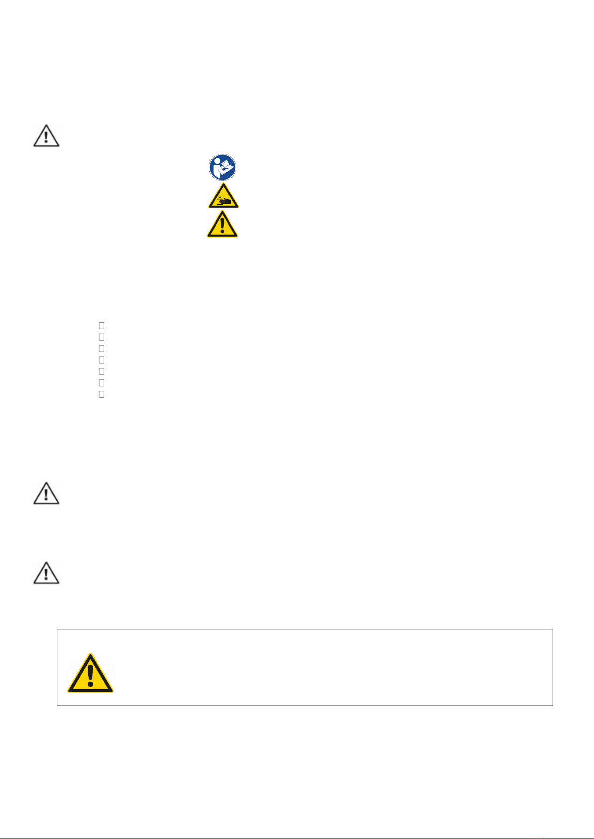
1.1 Applied symbols
Safety instructions and key sections in these operating instructions are marked with the exclamation mark
symbol on the left. Please pay particular attention to these instructions and sections.
Other symbols possibly used on the device:
Observe instructions for use:
Risk of pinching when adjusting:
Risk of hazard zone:
1.2 Applied standards
This device has been designed and manufactured in accordance with national and international regulations.
This ensures a very high level of equipment safety.
The models described here comply with the following regulations and directives:
Regulation (EU) 2017/745
DIN EN IEC 60601-1
DIN EN ISO 14971
DIN EN 60601-2-52 partly based on
DIN EN IEC 62353
DIN EN ISO 10993-5/-10
DGUV Regulation 3
This device is a Class 1 medical device according to Regulation (EU) 2017/745 (MDR).
1.3 Safety regulations
This section contains a summary of the most important safety information.
Correct operation of the device is essential for safe operation. Therefore, please familiarise yourself with the
contents of these instructions for use before using the device. We recommend that you keep these
instructions for use near the device for future reference.
The device may only be used by authorised, instructed and competent persons who are sufficiently familiar
with its adjustment mechanism or have read and understood the operating manual fully. The manufacturer
cannot be held responsible for damage caused by or involving unauthorised persons.
The user must ensure that the device is not accessible to unauthorised persons or cannot be operated by
unauthorised persons even when left unattended.
When leaving the device, it should be secured in such a way that unauthorised adjustment is impossible.
Important: Never leave the device unattended or accessible to third parties when it is ready for operation.
Keep a sufficient safety distance to the device during all adjustment procedures. Special attention
must be paid to the arms, hands, legs and feet of the user and the patient - RISK OF CRUSHING!
Make sure that there are no objects located directly around or underneath the device!
1.4 Intended purpose
The table is used for the ideal positioning of patients for the purpose of curative and disease treatment,
examination, massage and health therapy. Table operation and patient positioning on the table may only be
Dewert User Manual 6000E and 6800E –Updated 05.2021/1 MDR Page 3 of 15
performed by professionally trained persons who have been instructed in its use or who, through experience
with other similar medical devices, have knowledge of its proper use, taking into account possible hazards.
The device must only be moved within the room for cleaning or patient access. This device has been
developed exclusively for use indoors and in normal ambient conditions and can be used in the following
areas: laboratories, medical practices, examination and treatment rooms, hospitals, clinics, physiotherapy
practices, occupational therapy centres and doctors’ surgeries.
This table is not classed as surgical furniture and must, therefore, not be used for surgical purposes.
The expected service life is 10 years or 100,000 drive cycles (double stroke = 1x up and down).
1.5 Information on setup and use
When packed, the device may be exposed to the following environmental conditions for approx. 3 months:
Transport and storage temperature: -20° to + 50°
Operating temperature: +10° to +40°
Relative humidity: 30% to 75%
Air pressure: 800hPa to 1060hPa
When transporting the device in a vehicle, it must be secured properly against moving. To do so, lock the
castors (optional equipment) and ensure further safety measures.
When setting up the device, do not lift it at the head part, as this may damage the head part and/or the
release mechanism. Hold and lift the table on the left and right-hand side of the frame. The table must stand
securely on its feet or castors on a level, flat and solid surface. Before use, activate the brakes on the castors
and make sure they are working properly.
When transporting the table, take hold of the underframe, NOT the upper frame.
1.6 Commissioning
The device is ready for use upon delivery.
Remove the power cable from the film packaging on the underframe of the table and connect it properly to a
permanently installed mains socket. When routing the power cable, make sure the cable cannot be crushed,
rolled over or otherwise damaged.
Lock the castors (optional) or the wheel system (optional). As the operator, carry out a thorough and precise
function check once the device has been set up. Prior to commissioning, clean the device and remove any
contamination from transport. Make sure that no connecting cables from the hand or foot switch to the motor
are trapped in the mechanism and thus damaged.
Operation in potentially explosive atmospheres is not permitted.
1.7 Safety instructions
This table may only be used for its intended purpose. Any other use is strictly prohibited and possibly
dangerous. The manufacturer cannot be held responsible for damage caused by improper use. Patients may
only be positioned in preparation for treatment/examination by professionally trained persons.
Please note: This table is not classed as surgical furniture.
Prior to and when adjusting the height of the table, make sure that no persons or objects are located in the
adjustment range of the table and that nobody has their hands on the underframe.
The following basically applies: Never reach into or under the frame of the table when adjusting the height.
Height adjustment can result in injury if the user does not pay due care and attention. Therefore, take great
care when performing this procedure.
When adjusting the upholstery parts, make sure that no persons or objects are in the adjustment range. Make
sure that no persons reach under the upholstery part or lean on the underframe.
Important for the user: When adjusting the upholstery parts, do not reach under the spacers located beneath
the upholstery parts.
Always use both hands when adjusting the lying surface elements: Use one hand to operate the adjustment
mechanism and the other hand for the lying surface adjustment.

Dewert User Manual 6000E and 6800E –Updated 05.2021/1 MDR Page 4 of 15
The lying surfaces and the underframe are not anti-static as standard.
Our products are not intended for use in wet rooms and must under no circumstances be cleaned using so-
called bed washers. This would irreparably destroy the product.
The head part and armrests are only intended to support the patient and must not be used for sitting.
If the underframe is designed with movability (optional), all the castors must always be locked before using
the table.
Do not put a damaged device into operation.
Disconnect the device from the mains (power supply) in the event of a fault or during maintenance work.
To disconnect, be sure to grasp the plug, not the power cable.
This device must not be modified without the express permission of the manufacturer.
1.8 Model designation and type labelling
The exact model designation depends on the choice of frame colour:
-03 white aluminium powder coated (RAL 9006);
-04 grey aluminium powder coated (RAL 9007)
The type plate is attached to the underframe on one long side of the table. It provides information about key
table data.
The following symbols are listed there (by way of example), their meanings are:
Read the operating
manual
Serial no.
Applied part Type B
Caution, potential
hazard
Max. load
capacity
CE mark
Date of manufacture
Product may only
be used in dry
rooms
Do not dispose of with
household waste
Address of
manufacturer
Protection class I
1.9 Meaning of the serial number
The serial no. is located on the type plate or is shown separately next to the type plate of the table. This
number is unique and firmly linked to this specific individual product. It enables us to identify this table model
and trace back assemblies/safety-relevant components at any time.
Please always state this serial number when enquiring about spare parts.
2. Operating manual
2.1 Table design
When designing the table frames, special emphasis was placed on functional and operational safety. The
number of possible pinching points has thus been minimised, while remaining ones have been covered or
protected with spacers to prevent injury, thus ensuring safe and yet simple operation. Nevertheless,
necessary caution must always be exercised when using the table.

Dewert User Manual 6000E and 6800E –Updated 05.2021/1 MDR Page 5 of 15
The table consists of the following assemblies: underframe, telescopic column, upper frame and upholstery.
Depending on the respective version, these assemblies can feature further attachment parts. The surfaces of
the welded design are plastic coated. The lifting motor for the height adjustment is located inside the covered
telescopic column. The electrical adjustment system does not pose a hazard to the health and safety of the
user or the patient when used as intended. The lifting motor is activated by a low control voltage.
2.2 Height adjustment
Height adjustment
To adjust the height, the enclosed foot switch (optionally also hand switch) is operated according to the
marking. Beforehand, brief activation (double tap) must take place via the foot switch (or the hand switch).
Please refer to section 7. The table is lifted or lowered.
Height adjustment using foot switch rails (optional)
The electric motor for height adjustment is operated by a switch rail attached to the long side of the table,
which can be operated with your foot. Press the switch rail down = the table is lifted. Lift the switch rail up =
the table is lowered. Here, too, brief activation (double tap) must take place beforehand (see section 7). The
arrangement of the switch rails results in a changed lying surface height.
Note on operation
The electric motor is to be operated in intermittent duty mode. This means that a maximum duty cycle
of 25 s must not be exceeded. Before switching the motor back on, an interruption time of at least 400
s must be observed. If the maximum duty cycle is exceeded, an internal thermal switch (protective
temperature limiter) in the motor interrupts the power supply to the actuator. After the electric motor
has cooled down, the thermal switch automatically reconnects the power supply to the actuator.
2.3 Head part adjustment
Despite the very robust and strong design of the gas spring, the head part must not be used for
sitting!
Head part adjustment upwards and downwards (positive and negative direction) using a gas spring
The head part is adjusted using a gas spring. To operate, press the release lever, which is located at the end
of the head part underneath the upholstery part, in the direction of the upholstered surface. The head part is
lifted slowly to the positive end position. To lower, press down the head part and operate the release lever at
the same time. Once the desired position has been reached, let go of the release lever.
2.4 Adjustment of other sections
Despite their robust and strong design, the adjustable sections must not be used for climbing onto or
sitting on the table. The area provided for this purpose is located directly above the telescopic
column.
Lying surface adjustment to the inclined position using an electric motor
(models 6050E, 6051E, 6810E, 6075E, 6875E, 6085E, 6885E)
The foot part is adjusted using a separate electric motor. By operating the hand switch, the inclination of the
lying surface can be varied steplessly. Please also observe the necessary double-tap function (see section 7).
With the head part in downwards adjustment (negative position), at maximum inclination and when lowering
the table at the same time to the lowest position, attention must be paid to the head part.
Should the head part come into contact with the floor, the gas spring is automatically triggered and the head
part is lifted in upwards adjustment (positive direction). This is for emergency use only and is associated with
noise.
Always observe: There must be no persons in the adjustment range of the entire lying surface.
Upholstery segment adjustment using a gas spring
The upholstery segments are adjusted using one or more gas springs. To operate, press the release lever in
the direction of the upholstered surface. The upholstery part is lifted slowly to the positive end position. To
lower, press down the upholstered segment and operate the release lever at the same time. Once the desired
position has been reached, let go of the release lever. The strength of the gas spring ensures relative ease of
This manual suits for next models
1
Table of contents
Other Dewert Medical Equipment manuals


Popular Medical Equipment manuals by other brands


Getinge
Getinge Arjohuntleigh Nimbus 3 Professional Instructions for use

Mettler Electronics
Mettler Electronics Sonicator 730 Maintenance manual

Pressalit Care
Pressalit Care R1100 Mounting instruction

Denas MS
Denas MS DENAS-T operating manual

bort medical
bort medical ActiveColor quick guide

AccuVein
AccuVein AV400 user manual


