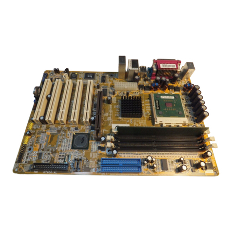
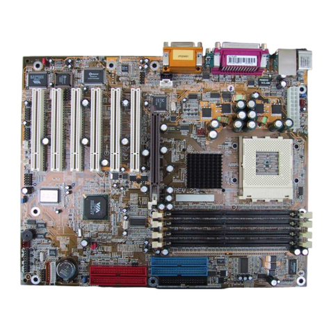
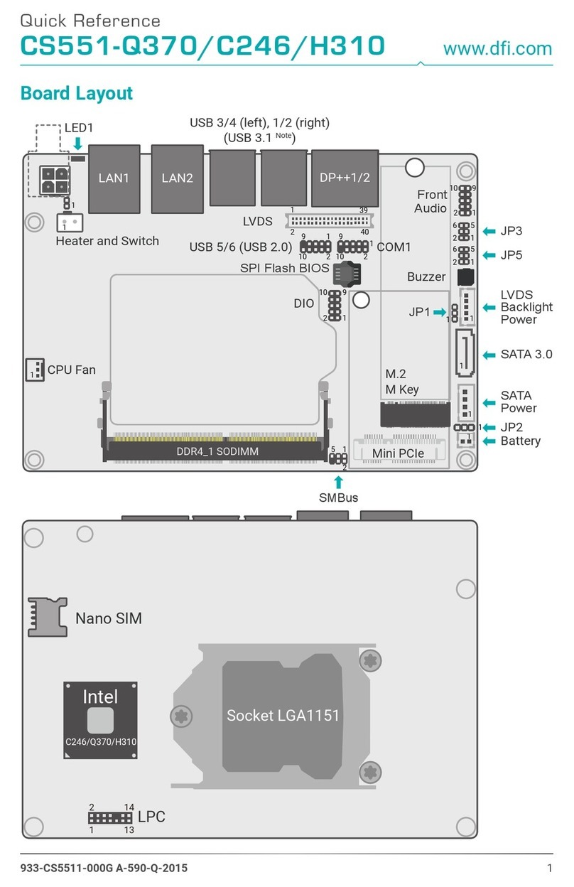
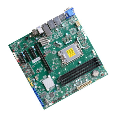
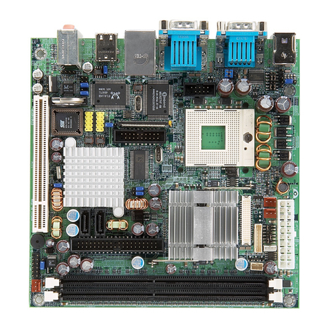
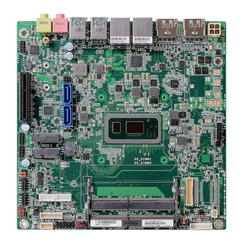
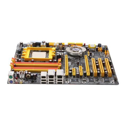
DFI LanParty NF3 Ultra-DF User manual

935-NF3UF1-000
88800535
System Board User’s Manual
Carte Mère Manuel Pour Utilisateur
System-Platine Benutzerhandbuch
Manual del Usuario de Placas Base
Ðóêîâîäñòâî ÏîëüçîâàòåëÿÐóêîâîäñòâî Ïîëüçîâàòåëÿ
Ðóêîâîäñòâî Ïîëüçîâàòåëÿ

2
Quick Setup Guide
1
Quick Setup
Guide
Copyright
This publication contains information that is protected by copyright. No part of it
may be reproduced in any form or by any means or used to make any
transformation/adaptation without the prior written permission from the copyright
holders. This publication is provided for informational purposes only. The
manufacturer makes no representations or warranties with respect to the
contents or use of this manual and specifically disclaims any express or implied
warranties of merchantability or fitness for any particular purpose. The user will
assume the entire risk of the use or the results of the use of this document.
Further, the manufacturer reserves the right to revise this publication and make
changes to its contents at any time, without obligation to notify any person or
entity of such revisions or changes. © 2005. All Rights Reserved.
Trademarks
Product names or trademarks appearing in this manual are for identification
purpose only and are the properties of the respective owners.
Caution
To avoid damage to the system, use the correct AC input voltage range.....
To reduce the risk of electric shock, unplug the power cord before removing the
system chassis cover for installation or servicing. After installation or servicing,
cover the system chassis before plugging the power cord.
Battery: 1. Danger of explosion if battery incorrectly replaced. 2. Replace only
with the same or equivalent type recommend
by the manufacturer. 3. Dispose of
used batteries according to the battery manufacturer’s
instructions.
Notice
The system board and accessories in the package may not come similar to the
information stated in this manual. This may differ in accordance to the sales region
or models in which it was sold. For more information about the standard
package in your region, please contact your dealer or sales representative.
FCC and DOC Statement on Class B
This equipment has been tested and found to comply with the limits for a Class
B digital device, pursuant to Part 15 of the FCC rules. These limits are designed
to provide reasonable protection against harmful interference when the
equipment is operated in a residential installation. This equipment generates, uses
and can radiate radio frequency energy and, if not installed and used in accord-
ance with the instruction manual, may cause harmful interference to radio
communications. However, there is no guarantee that interference will not occur
in a particular installation. If this equipment does cause harmful interference to
radio or television reception, which can be determined by turning the equipment
off and on, the user is encouraged to try to correct the interference by one or
more of the following measures:
• Reorient or relocate the receiving antenna.
• Increase the separation between the equipment and the receiver.
• Connect the equipment into an outlet on a circuit different from that to
which the receiver is connected.
• Consult the dealer or an experienced radio TV technician for help.
Notice:
1. The changes or modifications not expressly approved by the party
responsible for compliance could void the user's authority to operate the
equipment.
2. Shielded interface cables must be used in order to comply with the emission
limits.
3
1
Quick Setup Guide
Quick Setup
Guide
Table of Contents
Chapter 1
Quick Setup Guide.............................................
Chapter 2
English......................................................................
Chapter 3
Français....................................................................
Chapter 4
Deutsch...............................................................................
Chapter 5
Español............................................................................
Chapter 6
Ðóññêèé.......................................................................
4
16
20
23
27
31
The user’s manual in the provided CD contains detailed information about the system board. If, in some
cases, some information doesn’t match those shown in this manual, this manual should always be re-
garded as the most updated version.
Le manuel d’utilisateur dans le CD muni contient renseignement détaillé au sujet de carte de système. Si,
en quelque cas, quelque renseignement n’appareille de ce que dit dans ce manuel, ce manuel doit
toujours être considéré comme la plus nouvelle version.
Das Benutzerhandbuch in der angebotenen CD enthält detaillierte Informationen über die Hauptplatine.
Wenn in manchen Fällen manche Informationen nicht denjenigen Informationen dargestellt in diesem
Handbuch entsprechen, soll dieses Handbuch als die meist aktualisierte Ausgabe gelten.
El uso explicativo contene información detalle sobre la sistema board en el CD preparativo. Si en algún
caso, la información no es igual con el uso explicativo, necesita ver el uso explicativo, esque es más
nuevo.
 ðóêîâîäñòâå ïîëüçîâàòåëÿ íà ïðåäîñòàâëÿåìîì CD äèñêå ñîäåðæèòñÿ ïîäðîáíàÿ
èíôîðìàöèÿ î ìàòåðèíñêîé ïëàòå. Èíîãäà íàïå÷àòàííîå ðóêîâîäñòâî ìîæåò íå
ñîâïàäàòü ðóêîâîäñòâîì íà CD, òàê êàê ïîñëåäíåå íàèáîëåå ÷àñòî îáíîâëÿåòñÿ è
ÿâëÿåòñÿ ñàìûì ñâåæèì.

4
Quick Setup Guide
1
Quick Setup
Guide
System Board Layout
Chapter 1 - Quick Setup Guide

5
1
Quick Setup Guide
Quick Setup
Guide
System Memory
•DIMMs are on the same channel.
•DIMMs in a channel can be identical or
completely different. However, we highly
recommend using identical DIMMs.
•Not all slots need to be populated.
•DIMMs of the same memory configura-
tion are on different channels.
Single Channel
Dual Channel
Important:
If you are installing more than one double rank DDR400, the
maximum DRAM speed will automatically be limited to the speed of
a DDR333. However, the BIOS provides the option of manually
adjusting the speed to DDR400 by selecting “200” in the “Max
Memclock (Mhz)” field (Genie BIOS Setting submenu, DRAM
Configuration section) of the BIOS.
DDR 4 Channel B
DDR 2 Channel A
DDR 3 Channel B
DDR 1 Channel A

6
Quick Setup Guide
1
Quick Setup
Guide
Jumpers
2-3 On:
Clear CMOS Data
1-2 On: Normal
(default)
X
JP2
312312
Clear CMOS Data
BIOS Write Protect
X
J13
12 12
On:
BIOS Write
Protected
Off:
BIOS Not Write
Protected

7
1
Quick Setup Guide
Quick Setup
Guide
Rear Panel I/O Ports
PS/2
Mouse
PS/2
K/B COMS/PDIF-in
S/PDIF-out
USB 1-2 USB 3-4
1394_1 LAN
Parallel
Line-out
Line-in
Mic-in
S/PDIF-in
S/PDIF-out
W
S/PDIF
WJ3
15
+5V
Key
SPDIF out
GND
SPDIF in
I/O Connectors
Note:
DO NOT use RCA S/PDIF and optical S/PDIF at the same time.

8
Quick Setup Guide
1
Quick Setup
Guide
IEEE 1394
1394_1
W
W
1394_2
TPA+
TPA-
Ground Ground
TPB- TPB+
Key
+12V (fused)
+12V (fused)
Ground
12
10 9
Universal Serial Bus Ports
USB 4
USB 3
W
USB 7-8
USB 5-6
W
USB 2
USB 1
1
VCC
-Data
+Data
Ground
Key
VCC
-Data
+Data
Ground
N. C.
210
9
X

9
1
Quick Setup Guide
Quick Setup
Guide
Front audio W
Audio (Rear Audio and Front Audio)
Mic-in
Line-out
Line-in
W
1
Mic
Mic Power
AuD_R_Out
N. C.
AuD_L_Out
GND
AuD_Vcc
Key
210
9
AuD_R_Return
AuD_L_Return
Rear audio
Light Blue
Lime
Pink
2-channel
Line-in
Line-out
Mic-in
4-channel
Rear R/L
Front R/L
Mic-in
6-channel
Rear R/L
Front R/L
Center/Subwoofer

10
Quick Setup Guide
1
Quick Setup
Guide
Floppy Disk Drive Connector
X
34 33
21
DRAM Power LED and Standby Power LED
DRAM Power LED
Standby Power LED
Important:
When the DRAM Power LED lit red, it indicates that power is
present on the DDR sockets. Power-off the PC then unplug the
power cord prior to installing any memory modules. Failure to do so
will cause severe damage to the motherboard and components.

11
1
Quick Setup Guide
Quick Setup
Guide
Important:
Before creating RAID, make sure you have installed the Serial/Parallel
ATA drives and connected the data cables otherwise you won’t be
able to enter the NVIDIA RAID BIOS utility.
Serial ATA Connectors
SATA 1 (J21)
SATA 2 (J20)
SATA 4 (J11)
SATA 3 (J10)
71
GND
TXP
TXN
GND
RXN
RXP
GND
IDE Disk Drive Connector
40 39
21
SEC IDE
SEC IDE
PRI IDE
40 39
21
PRI IDE

12
Quick Setup Guide
1
Quick Setup
Guide
Note:
The sequence of the pin functions on some IR cable may be
reversed from the pin function defined on the system board. Make
sure to connect the cable connector to the IR connector according to
their pin functions.
IrDA Connector
W
15
VCC
N. C.
IRRX
Ground
IRTX
CD-in Internal Audio Connector
W
14
Right audio
channel
Left audio
channel
Ground Ground

13
1
Quick Setup Guide
Quick Setup
Guide
Important:
To ensure that adequate power is provided, we strongly recommend
that you use a minimum of 400 Watt (or greater) power supply.
Cooling Fan Connectors
2nd fan
X
X
Chassis fan
13
Ground
Power
Sense
31
Ground
Power
Sense
CPU fan
X
31
Ground
Power
Sense
Power Connectors
X
X
+12V
111
10
3.3V
3.3V
Ground
+5V
Ground
+5V
Ground
PW-OK
5VSB
+5V
3.3V
-12V
Ground
PS-ON
Ground
Ground
Ground
-5V
+5V
20
4
31
2
+12V
Ground
Ground
+12V

14
Quick Setup Guide
1
Quick Setup
Guide
Pin
3
5
14
16
8
10
18
20
7
9
13
15
17
19
2
4
6
HD-LED
(Primary/Secondary IDE LED)
Reserved
ATX-SW
(ATX power switch)
Reserved
RESET
(Reset switch)
SPEAKER
(Speaker connector)
PWR-LED
(Power/Standby LED)
Pin Assignment
HDD LED Power
HDD
N. C.
N. C.
PWRBT+
PWRBT-
N. C.
N. C.
Ground
H/W Reset
Speaker Data
N. C.
Ground
Speaker Power
LED Power (+)
LED Power (+)
LED Power (-) or Standby Signal
Front Panel Connectors
X
J19
1
219
20
HD-LED
PWR-LED
ATX-SW
RESET SPEAKER

15
1
Quick Setup Guide
Quick Setup
Guide
EZ Touch Switches
X
The presence of the power switch and reset switch on the system
board are user-friendly especially to DIY users. They provide
convenience in powering on and/or resetting the system while fine
tuning the system board before it is installed into the system chassis.
Power Switch
Reset Switch

16
English
2
English
Chapter 2 - English
Features and Specifications
Processor
• AMD AthlonTM 64 FX / AthlonTM 64 / SempronTM
• 2000MT/s HyperTransport interface
• Socket 939
Chipset
• NVIDIA nForce3 Ultra
System Memory
• Four 184-pin DDR SDRAM DIMM sockets
• Supports dual channel (128-bit wide) memory interface
• Supports up to 4GB system memory
• Supports PC2100 (DDR266), PC2700 (DDR333) and PC3200
(DDR400) DDR SDRAM DIMM
• Supports x8/x16 ECC/non-ECC unbuffered DIMMs, up to
512Mb DDR devices
BIOS
• Award BIOS
• CPU/DRAM/AGP overclocking
• CPU/DRAM/Chipset overvoltage
• 4Mbit flash memory
• AMD Cool‘n’QuietTM technology
Energy Efficient Design
• Supports ACPI specification and OS Directed Power
Management
• Supports ACPI STR (Suspend to RAM) function
• Wake-On-Events include:
- Wake-On-PS/2 Keyboard/Mouse
- Wake-On-LAN
- Wake-On-Ring
- RTC timer to power-on the system
• AC power failure recovery

17
2
English
English
Hardware Monitor
• Monitors CPU/system temperature
• Monitors VCC3/5V/12V/5Vsb/Vbat voltages
• Monitors the speed of the cooling fans
• CPU Overheat Protection function monitors CPU temperature
during system boot-up
Onboard Audio Features
• Realtek 6-channel audio CODEC
• True stereo line level outputs
• S/PDIF-in/out interface
Onboard LAN Features
• Gigabit Phy
• Fully compliant to IEEE 802.3 (10BASE-T), 802.3u (100BASE-TX)
and 802.3ab (1000BASE-T) standards
IDE Interface with NVIDIA RAID
• Supports two IDE connectors that allow connecting up to four
UltraDMA 133Mbps hard drives
• NVIDIA RAID allows RAID arrays spanning across Serial ATA
and Parallel ATA
• RAID 0, RAID 1, RAID 0+1 and JBOD
Serial ATA Interface with NVIDIA RAID
• Four Serial ATA interfaces with speed up to 1.5Gbps
- Two Serial ATA ports supported by nForce3 Ultra chip
- Two Serial ATA ports supported by Marvell SATA PHY
• NVIDIA RAID allows RAID arrays spanning across Serial ATA
and Parallel ATA
• RAID 0, RAID 1, RAID 0+1 and JBOD
IEEE 1394 Interface
• VIA VT6307
• Supports two 100/200/400 Mb/sec ports
Accelerated Graphics Port (A.G.P.)
• Supports AGP 8x up to 2132MB/sec. and AGP 4x up to
1066MB/sec. bandwidth for 3D graphics applications
• Supports 0.8/1.5V add-in cards

18
English
2
English
Rear Panel I/O Ports
• 1 PS/2 mouse port
• 1 PS/2 keyboard port
• 1 DB-25 parallel port
• 2 S/PDIF RCA jacks (S/PDIF-in and S/PDIF-out)
• 1 DB-9 serial port
• 1 IEEE 1394 port
• 1 RJ45 LAN port
• 4 USB 2.0/1.1 ports
• Line-in, line-out and mic-in jacks
I/O Connectors
• 2 connectors for 4 additional external USB 2.0/1.1 ports
• 1 connector for 1 external IEEE 1394 port
• 1 front audio connector for external line-out and mic-in jacks
• 1 CD-in internal audio connector
• 1 S/PDIF connector for optical cable connection
• 1 IrDA connector
• 4 Serial ATA connectors
• 2 IDE connectors
• 1 floppy connector
• 1 20-pin ATX power connector
• 1 4-pin ATX 12V power connector
• 1 front panel connector
• 3 fan connectors
• EZ touch switches (power switch and reset switch)
Expansion Slots
• 1 AGP 8x/4x slot
• 5 PCI slots
PCB
• ATX form factor
• 30.5cm (12") x 24cm (9.44")

19
2
English
English
Package Checklist
The system board package contains the following items:
;The system board
;A user’s manual
;Two IDE round cables
;One floppy round cable
;Two Serial ATA data cables
;One Serial ATA power cable
;One “nVRAID Driver” diskette
;One I/O shield
;One “Mainboard Utility” CD
If any of these items are missing or damaged, please contact your
dealer or sales representative for assistance.

20
Français
3Français
Français
Chapter 3 - Français
Caractéristiques et Spécifications
Processeur
• AMD AthlonTM 64 FX / AthlonTM 64 / SempronTM
• Interface HyperTransport 2000MT/s
• Socket 939
Chipset
• NVIDIA nForce3 Ultra
Mémoire Système
• 4 sockets DDR SDRAM DIMM 184 broches
• Supporte l’interface de mémoire deux canaux (128-bit)
• Supporte jusqu’à 4GB de mémoire
• Supporte DDR SDRAM DIMM PC2100 (DDR266), PC2700
(DDR333) et PC3200 (DDR400)
• Supporte exclusivement les modules DIMM ECC/non-ECC x8/
x16, densité de RAM jusqu’à 512Mb, DIMM non-tamponnés
BIOS
• Compatible avec Award BIOS
• Overclocking de CPU/DRAM/AGP
• Contrôle du voltage de CPU/DRAM/Chipset
• Mémoire Flash 4Mbit
• AMD Cool‘n’QuietTM technologie
Design à Haut Rendement Énergétique
• ACPI STR (Suspend to RAM) fonction
• Réveil-Sur-PS/2 Clavier/Souris
• Eveil Sonnerie et Réveil Par Le Réseau
• Minuterie RTC pour allumer le système
• Récupération après Défaillance d’Alimentation CA
System Health Monitor Fonctions
• Gère l’alarme de température et de surchauffe de CPU/système
• Gère l’alarme de voltage et d’échec de VCC3/5V/12V/5Vsb/
Vbat
• Gère la vitesse de ventilateur du ventilateurs
• Protection du CPU - supporte la mise hors circuit automatique
en cas de surchauffage du système
Table of contents
Languages:
Other DFI Motherboard manuals
Popular Motherboard manuals by other brands

Taiwan Commate Computer Inc.
Taiwan Commate Computer Inc. LV-671Z user manual

Sangamo
Sangamo CHPPR3 User instructions

Raspberry Pi
Raspberry Pi RoboPi user manual

VIA Technologies
VIA Technologies EPIA-PE operating guide

Gigabyte
Gigabyte H310M S2H 2.0 user manual

Supermicro
Supermicro C7B360-CB-M Quick reference guide