3User's Manual | WL053
Table of Contents
Chapter 1 - Introduction................................................................................................................6
Specifications ......................................................................................................................... 6
Features .................................................................................................................................. 7
Chapter 2 - Hardware Installation................................................................................................8
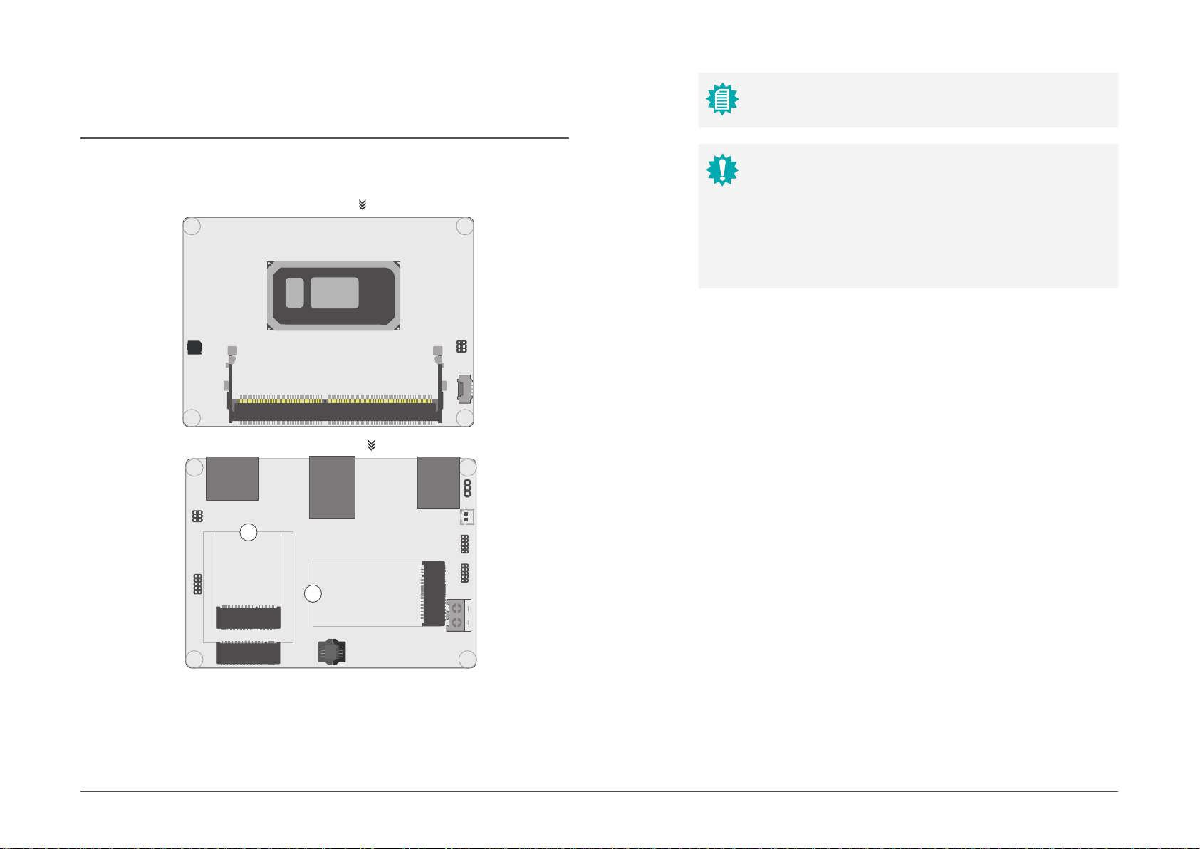
Board Layout........................................................................................................................... 8
Front Panel.......................................................................................................................8
1Buzzer............................................................................................................................ 8
COM1................................................................................................................................ 8
DP++/................................................................................................................................ 8
HDMI................................................................................................................................. 8
M.2-B(R1) ......................................................................................................................... 8
M.2-E................................................................................................................................. 8
LAN ................................................................................................................................... 8
M.2-B(R0) ......................................................................................................................... 8
SPI..................................................................................................................................... 8
USB ................................................................................................................................... 8
3.1 ..................................................................................................................................... 8
1SMBus.......................................................................................................................... 8
CPU Fan............................................................................................................................ 8
JP1.................................................................................................................................... 8
Battery .............................................................................................................................. 8
USB 2 6/7 ......................................................................................................................... 8
DIO .................................................................................................................................... 8
DC-in ................................................................................................................................. 8
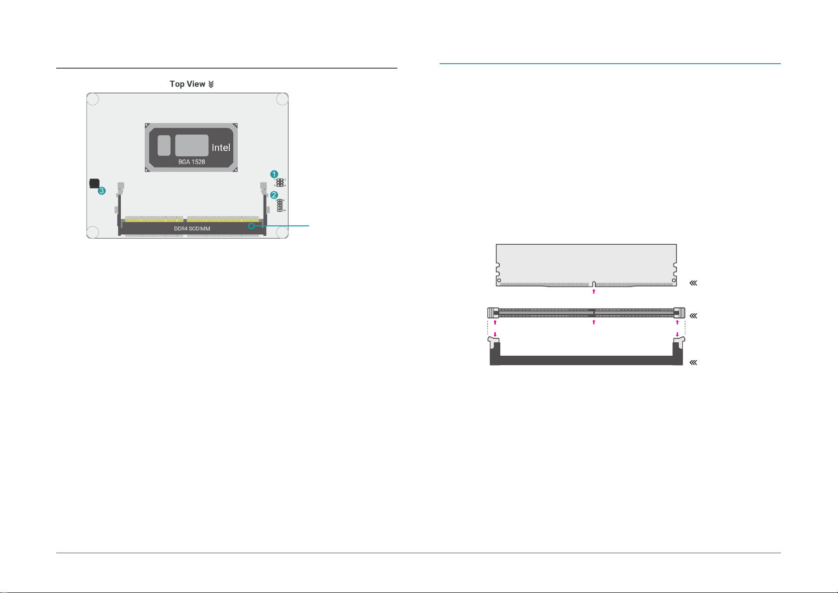
System Memory ..................................................................................................................... 9
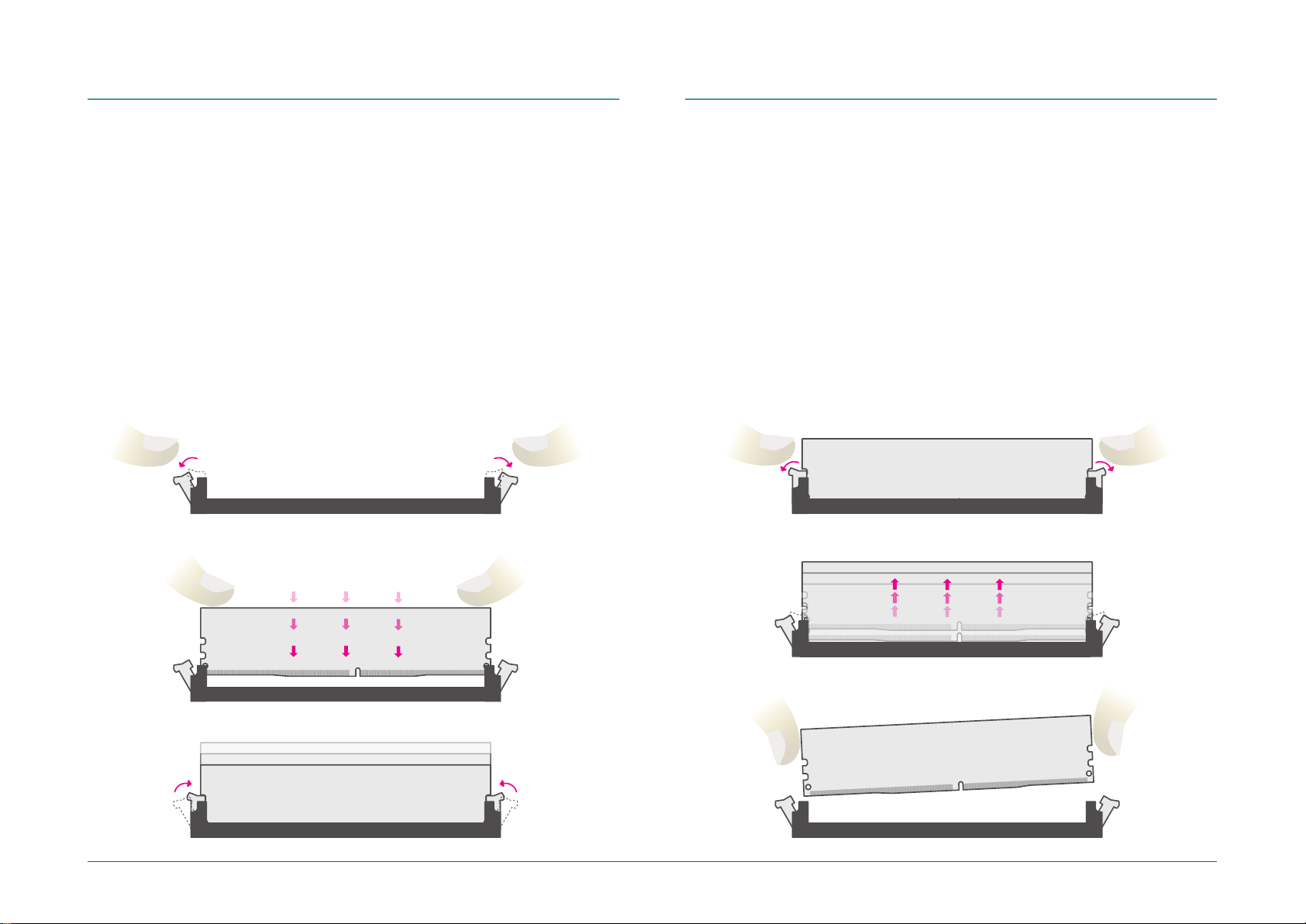
Installing the Memory Module........................................................................................9
Removing the Memory Module ....................................................................................10
Installing the Heat spreader .........................................................................................11
Jumper Settings ...................................................................................................................13
Clear CMOS....................................................................................................................13
Rear I/O Ports.......................................................................................................................14
USB Ports .......................................................................................................................14
Graphics Display............................................................................................................15
LAN .................................................................................................................................15
Internal I/O Connectors .......................................................................................................16
SMBus ............................................................................................................................16
CPU Fan..........................................................................................................................16
USB Ports .......................................................................................................................17
Digital I/O .......................................................................................................................18
COM1..............................................................................................................................18
Power Connector...........................................................................................................19
Front Panel.....................................................................................................................20
Battery Header...............................................................................................................21
Chapter 3 - BIOS Settings...........................................................................................................22
Overview ...............................................................................................................................22
Main.......................................................................................................................................23
Advanced .............................................................................................................................23
RC ACPI Configuration..................................................................................................24
CPU Configuration.........................................................................................................24
Power & Performance ...................................................................................................25
PCH-FW Configuration ..................................................................................................25
Trusted Computing........................................................................................................26
NCT5525D Super IO Configuration ..............................................................................27
NCT5525D HW Monitor ................................................................................................28
Serial Port Console Redirection ...................................................................................29
USB Configuration .........................................................................................................30
CSM Configuration ........................................................................................................30
USB Power Control........................................................................................................31
Network Stack Configuration........................................................................................31
Chipset ..................................................................................................................................32
Chipset ..................................................................................................................................32
Graphics Configuration .................................................................................................32
PCH-IO Configuration....................................................................................................33
PCI Express Configuration............................................................................................33
SATA And RST Configuration .......................................................................................34
HD Audio Configuration ................................................................................................34
Security .................................................................................................................................35
Security .................................................................................................................................35
Secure Boot....................................................................................................................35
Boot .......................................................................................................................................37
Save & Exit ............................................................................................................................37
Updating the BIOS................................................................................................................38
Notice: BIOS SPI ROM..........................................................................................................38