DHG MiniLift200 User manual

IFU No. 874-ML Ver. 18 2022-01-18
SWL: 200 kg/441 lbs
401100334
User manual – English
Bruksanvisning – Svenska
Brukermanual – Norsk
Brugsvejledning – Dansk
Käyttöohje – Suomi
Gebrauchsanweisung – Deutsch
Handleiding – Nederlands
Manuel d’utilisation – Français
Manuale utente – Italiano
Manual de usuario – Español
Návod k použití – Český
Instruções de utilização - Português
Návod na použitie – Slovensky
MiniLift200

Table of contents
English...............................................................................................................3
Svenska..........................................................................................................19
Norsk................................................................................................................35
Dansk...............................................................................................................51
Suomi..............................................................................................................67
Deutsch...........................................................................................................83
Nederlands....................................................................................................99
Français........................................................................................................115
Italiano..........................................................................................................131
Español.........................................................................................................149
Český.............................................................................................................163
Português...................................................................................................179
Slovensky...................................................................................................196
Dimensions.................................................................................................212
Symbols..........................................................................................213

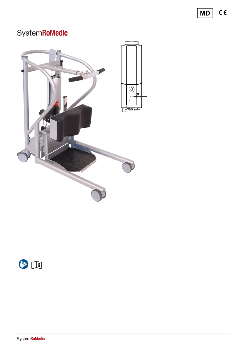
MiniLift200 is a mobile sit-to-stand lift which has been developed to, as gently as possible, assist the user when rising
from a sitting to a standing position. When MiniLift200 is combined with the appropriate lifting accessories, the user gets
support under the feet, for the front of the lower legs and behind the back, which provides for a safe and secure
sit-to-stand procedure. The construction safely moves the user forwards and upwards in a natural movement pattern
and, at the same time, the leg muscles and balance is exercised.
1. Lift arm
2. Hooks for lift vest/sling
3. Hand control
4. Leg support
5. Footplate
6. Rear castor wheels with brakes
7. Battery
8. Emergency stop
9. Adjustment of leg support
10. Manual emergency lowering
11. Electrical emergency lowering
12. Charging lamp
13. Front castor wheels
14. Locking mechanism for adjustment of lift arm
3
14
2
1
7
10
4
9
5
6
13
811
12
• Always read the user manuals for all assistive devices used during a transfer.
• Keep the user manual where it is accessible to users of the product.
• Always make sure that you have the right version of the user manual.
• The most recent editions of user manuals are available for downloading from our website,
www.directhealthcaregroup.com
• Under no circumstances may the lift be used by persons who have not received instruction in the operation of the lift.
• It is strongly prohibited to modify the original product.
Always read the user manual
Instructions for use - English
MiniLift200
3IFU

Assembly of MiniLift200
Check to ensure that all components are included:
Lift unit, control box and battery pack, undercarriage and base-width adjustment motor, footplate, leg support, hand
control and cord, manual and charger.
Connect cables: Hand control cord in HS, cable to lift unit on mast in outlet
M1, and cable to base-width motor in outlet M2.
Safety Switch Label: Select a label in a suitable language informing on
how to reset the Safety Switch. Attach the label on the upper side of
the lifting arm.
HS M1 M2
HOLD2 sec
1
HOLD2 sec
2
PUSH
PUSH
Visual inspection
• Inspect the packaging for any damage.
• Check for correct product being delivered.
• Inspect lift functions regularly.
• Check to ensure that material is free from damage.
Before use
• Check if all the parts/components are included in the packaging.
• Check if all approved accessories are included in the package.
• Check if Product Quality Approval document is included in the packaging. Save this document for future contact
with manufacturer.
• Make certain the lift is properly assembled.
• Check lifting function and base-width adjustment.
• Check driving function in all directions.
• Check sling bar connection and safety latch function.
• Check to ensure that the quick-connecting locking pin for the actuator is correctly installed.
Safety information
4IFU

Final inspection
Check to ensure that no parts have been left in the packaging.
Inspect the lift for signs of wear and damage.
Check all four castor wheels and castor wheel locks.
Check all connections and fixtures including screws and bolts.
Check the emergency stop function by activating the emergency stop, and then
pressing either the up or down button. If nothing happens when the up or down
buttons are pressed, the emergency stop is functioning properly.
Grasp the hand control, press the up button and run the lift arm all the way up. Then,
press the down button and run the lift arm all the way down.
Test base-width adjustment function. Press the button for base-width adjustment to
widen the base fully, and then press the other button to narrow the base again.
Test lift function by lifting a person (not a user) using an approved sling. At the same
time, check the emergency lowering function with someone on the lift. See section on
Emergency lowering.
If the lift is functioning correctly, connect the charger and check to ensure that the
charging lamp on the control box lights up.
NOTE!
Before the lift is used for the first time:
• it must be charged for at least 4 hours. See section on charging batteries.
• the control box service counter needs to be reset. To reset the service counters
press both lift buttons on the hand control at the same time for 5 seconds.
An audio signal will indicate that the timer has been reset.
Keep the user manual where it is accessible to users of the product.
5IFU

Using the product
Contraindications, Precautions, Warnings:
Contraindications
• The floor lifts may not be used by patients above the maximum weight indicated on the label of the lifts.
• The lift must not be lowered into water or used in a shower.
• The lift must not be left or stored in a damp or humid environment.
• The lift must not be cleaned using steam.
• The lift must not be charged in a wet room.
• The lift must not be used in oxygen-enriched environments.
• The floor lift must not be used outdoors, only indoors.
• The lift is not intended for long transporting of users, only for short transfers.
Precautions
• Check that the floor lift is used on a dry and proper levelled surface.
• Check the floor lift is correctly mounted/assembled before its first use.
• Check the floor lift after every folding/disassembly after any transport.
• Check lifting motion and inspect the actuators full range.
• Inspect the lift once per year to detect any signs of damage.
• Check that the hand control does not show signs of wear.
• Check that the hand control markings are in accordance with the lifting functions.
• Check the battery status.
• During yearly service note the number of lift the actuator as performed and take action accordingly.
• It is important to never leave the user alone during the transfer.
• Warranty applies only if repairs or alterations are made by personnel who are authorized by Direct Healthcare Group.
• Ensure that there are no obstacles or people in the way of the lift.
• Handle the battery with care. Do not drop.
• Use only batteries and cables that are intended for the lift.
• Verify that all lifting accessories aligns with gravity and can move freely.
• Activate the brakes whenever the lift is not in use.
• Low speed is recommended when moving a lift when a user is using it.
• Take care not to drive the floor lift over thresholds with high speed or force.
• When passing over a threshold, pass the back wheel of the floor lift first. Approach the threshold with lower speed
and communicate the coming threshold to the user.
6IFU

Safe working load
Different products on the same lift system (lift unit, sling bar, sling, scales and other lifting accessories) may have different
allowable safe working loads. The lowest allowable safe working load always determines the safe working load of the
assembled system. Always check the safe working loads for the lift and accessories before use. Contact your dealer if
you have any questions.
To transfer with MiniLift200, the user must be able to:
• support weight while standing
• understand instructions
Warnings
• Ensure that the user’s feet do not get caught between the footplate and the floor. Ensure that the user’s feet do not
get caught between the footplate and the base when adjusting the base width, or that a caregiver’s hands do not
get caught or pinched if adjusting the user’s feet on the footplate.
• Do not use the calf strap accessory without also using a sling that is appropriate for the MiniLift, such as the
ThoraxSling.
• To transfer with MiniLift200, the user must be able to support weight while standing.
The control box and battery have the following features
1. Emergency stop
2. Charging lamps
3. Display showing battery charge level
4. Connection for charger cable
5. Connection for base-width adjustment motor
6. Connection for lift arm actuator
7. Connection for hand control
8. Electrical emergency lowering
9. Handle for lifting battery
1
7
65
4
3
2
2
9
8
7IFU
Charging batteries
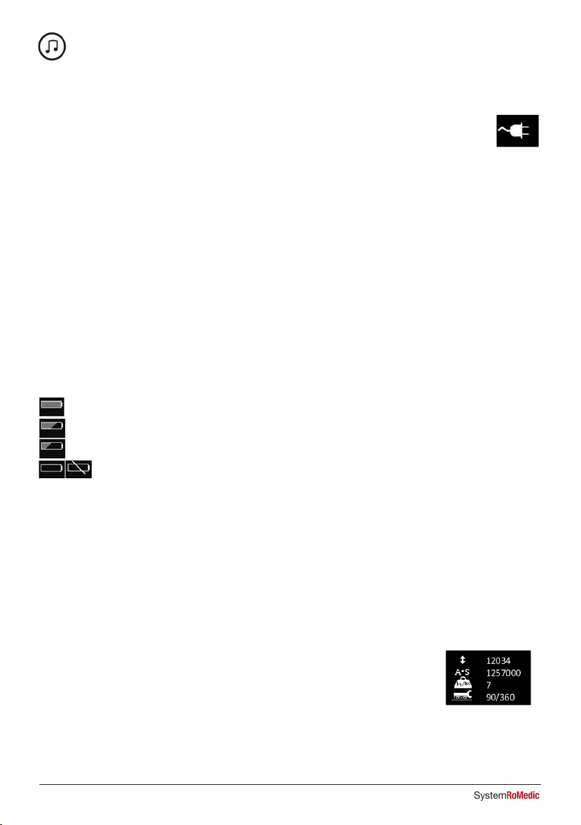
A tone sounding when using the lift indicates that the battery need recharging.
Charge the lift after use to ensure that the battery is always fully charged.
Lock the castor wheels when charging the battery.
1. Connect the charging cable to a power outlet and in the connection for charger cable.
The symbol for charging is shown on the display.
2. Check to ensure that the lamps on the control box light up. The green LED lamp indicates that the charger is receiving
power and the yellow LED lamp indicates that the battery is charging.
3. Charging stops automatically when the battery is fully charged.
Wall-mounted charger.
1. Remove the battery pack from the lift and place it in the wall-mounted charger.
2. Check to ensure that the LED lamp on the front of the charger lights up.
NOTE!
Before the lift is used for the first time, it must be charged for at least 4 hours.
For maximum battery life, charge batteries regularly. We recommend daily charging when the lift is used daily.
The emergency stop must be deactivated during charging.
Battery information on the display
The battery discharging will be shown in four stages:
Battery state 1: The battery is ok, no need for charging (100 - 50 %).
Battery state 2: Battery needs charging. (50 - 25 %)
Battery state 3: Battery needs charging. (Less than 25 %) A tone sounds when a button is pressed in
this battery state.
Battery state 4: The battery needs charging (17V or lower). At this stage some of the functionality of the lift
is lost. At this battery stage it is only possible to drive the lifting arm down. Furthermore an audio signal will
sound when a control button is activated. The symbol will switch between the two pictures for 10 seconds.
The battery symbol is shown when the box is active until power down (2 minutes after use).
It is not possible to use other batttery types than BAJ1/BAJ2.
The battery level is measured via voltage level. This means that it is possible to experience e.g. that
the battery switches from state 1 to state 2 and back to state 1.
Service information read-out
Basic service information can be read out on the display. To get the service information on the
display please press the lifting arm up button for half a second. The information will be shown
for ½ minute or until other buttons are activated.
• Total cycles done by the actuator
• Total work done by the actuator (ampere usage times seconds in use)
• Total number of overloads
• Days since last service/Days between services
8IFU
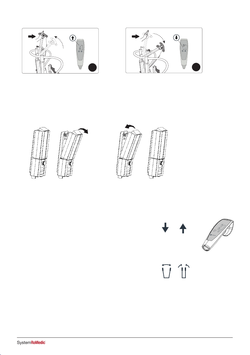
Hand control
Raising/lowering the lift arm
Symbol indicate direction of travel.
Motion stops as soon as the button is released.
If the lift arm encounter an obstacle while lowering, the lift will immediately
stop the motion. In order to continue, the lift arm will need to be raised
slightly by using the hand control before further lowering.
Widening/narrowing the base
Markings on the buttons indicate function.
Motion stops as soon as the buttons are released.
Changing the battery
”Click!”
12
How to reset the safety switch
1. Push down on the lift arm while holding the UP
button on the hand control for two seconds. 2. Push down on the lift arm while holding the DOWN
button on the hand control for two seconds.
HOLD 2 sec
1
HOLD 2 sec
2
PUSH
PUSH
HOLD 2 sec
1
HOLD 2 sec
2
PUSH
PUSH
9IFU
Manual emergency
lowering
Electrical emergency
lowering
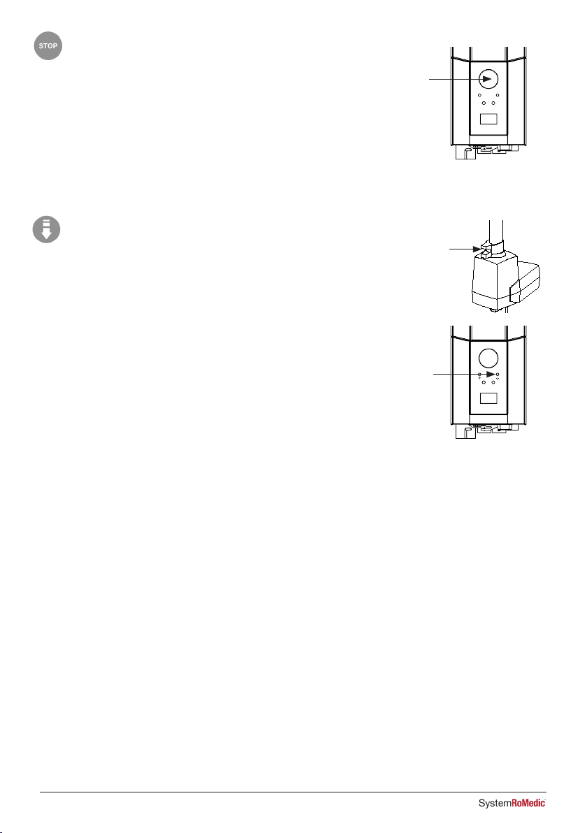
Emergency stop
To activate the emergency stop
Press the red emergency stop button on the control box.
Resetting
Turn the button in the direction of the arrows until the button pops out.
To prevent battery discharge, we recommend that the emergency-stop
button is pressed in when the lift is not in use.
Emergency lowering
Manual emergency lowering
For manual emergency lowering, turn the round plastic knob on the
actuator clockwise.
Electrical emergency lowering
For electrical emergency lowering, use the down button on the control
box. Use a narrow object such as a pen.
Instructions for use
These instructions must be followed for correct use of MiniLift200.
Hand control functions
The hand control has four functions: up and down (lift arm), out and in (base width).
Two functions cannot be used at the same time.
NOTE: The hand control functions do not operate if the emergency stop button is activated
NOTE: MiniLift200 may only be used for short transfers. It is not intended for transporting users.
Caution Never move the lift by pulling on the actuator.
Caution Ensure that the user’s feet do not get caught between the footplate and the floor. Ensure that the user’s feet do
not get caught between the footplate and the base when adjusting the base width.
10 IFU

Instructions for use for MiniLift
1. Before using the MiniLift, always plan and asses the risk before a lift
and transfer:
a. Check that the environment is suitable and plan for the task
b. Check the MiniLift and ThoraxSling function
c. Check the MiniLift battery
d. Check that the MiniLift has been serviced
e. Visually inspect the MiniLift and ThoraxSling for signs of damage
or defects
f. Ensure sizing of the ThoraxSling is correct in accordance with IFU
2. Requirements for use:
a. The client must have some standing capability to use the MiniLift –
this is dependent on the individual risk assessment.
Fitting the ThoraxSling
3. Fit the ThoraxSling to the client according to the ThoraxSling instructions –
see IFU for ThoraxSling.
4. The strap around the midriff should be no more than 10cm apart or
overlapping – if they are, consider a bigger or smaller size.
5. Buckle the safety belt. Do a risk assessment if the belt needs to be
buttoned, if case the client uses a stomia bag, PEG, has wounds or
similar. Raising a client with the MiniLift will work well even without
buckling the safety belt.
Introducing the MiniLift
6. If needed, to get closer to the wheelchair, lift the client’s feet from the
wheelchair to foot support and turn these away.
7. Spread the legs of the MiniLift as wide as necessary and position the
MiniLift in front of the client, facing the client.
8. When the MiniLift is correctly positioned in front of the client, lock the
wheels of the MiniLift and of the wheelchair/bed if applicable.
9. Ensure that the client’s feet have contact with the footplate and position
the client’s feet appropriately on the footplate of the MiniLift, to ensure
maximum balance.
10. Adjust the leg support height and depth position so that the client’s shins
are supported.
11. Lift the locking handle on the lift arm and set the lift arm so that the patient
can reach it comfortably with bent arms.
12. Attach suitable loops of the ThoraxSling on the hooks on the lift arm.
13. Pull the trombone arm back and lock the handle on the lift arm so that the
loops of the sling are under tension and are not slacking.
1
2
3
4
5
11IFU

14. Place the client’s hand on the handles of the lift arm,
thumbs over the top of the handles. Alternatively,
let the client push off from the armrests of the
wheelchair. For clients with reduced muscle function
in the arms, place the arm/s in ThoraxSling armrest.
15. Consider different patterns or ways of raising the
client:
a. Suitable for a shorter and more active client:
Short setting of the lift arm results in a more
forward leaning position that requires more muscle
strength in the legs.
b. Suitable for a taller client or weaker client:
Long setting of the lift arm is more suited for a
weaker patient who needs training.
16. Instruct the client about the Standing Activity – Not
Lifting.
17. Caregiver positioning: The caregiver should stand
on the side of the lift and press the UP button on the
hand control. Watch the foot placement of the client
and ensure that the ThoraxSling does not slip and the
feet position don’t change, ensuring as best a stand
as possible.
18. Raise the client to a position where he/she can stand
upright. It is important to note that some clients might
not want to stand upright for fear of falling forward.
19. Depending on client’s stability, have the client adjust
their hand positions to the frame of the MiniLift if
needed.
20. Unlock the wheels of the MiniLift.
21. When transferring the patient, close the leg-spreading
of the MiniLift and move the MiniLift so that the
patient faces forward.
22. Perform desired activity: e.g. transfer, standing
training, toileting.
23. Once client is in the desired standing position, move
the MiniLift to the intended transfer position.
24. Lock the wheelchair or chair/Bed, if the client is to be
lowered there, if needed.
25. Positions the client’s hands on the lift arm’s handles.
26. The caregiver’s position should, if possible, be
standing to the side of the MiniLift. Press the DOWN
button on the hand control to lower the client.
27. Position wheelchair, other chair, or bed in position to
enable best final sitting position.
28. Keep on lowering the lift arm and ensure that the
client ends up well positioned in the sitting position
(e.g. in a wheelchair).
29. Let the client remove their hands from the MiniLift,
extend the lift arm and detach the ThoraxSling
completely from the MiniLift.
30. Unlock the MiniLift wheels, if required, and carefully
remove the client’s feet from the MiniLift’s footplate.
31. Move the MiniLift away from the client.
32. Remove the ThoraxSling from the client.
Helpful hint:
Use a longer loop alternative for short users and for users that cannot be fully raised.
Use a shorter loop alternative for taller users, and pull the lift arm out to allow the user to rise to a standing position.
1
2
3
4
5
12 IFU
Trouble-shooting
If the lift or base-width adjustment cannot be activated, check the following:
- That the emergency stop button is activated.
- That all cables are properly and securely connected. Pull out the contact and plug it in again firmly.
- That battery charging is not in progress.
- That the battery is charged.
If the lift is not working properly, contact your dealer.
If the lift makes unusual noises:
- Try to determine the source of the sound. Take the lift out of operation and contact your dealer.
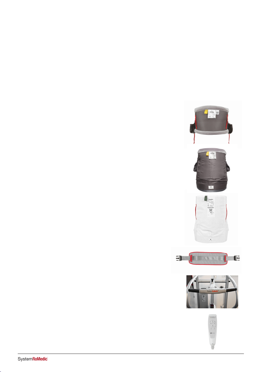
Accessories
Expected lifetime of accessories
Consult the manual or information sheets regarding the respective accessories.
ThoraxSling, polyester, XS-XXL, article no.: 45500003-009
ThoraxSling, wipeable, S-XXL, article no.: 45500004-009
ThoraxSling, with seat support, polyester, S-XL, article no.: 45600004-008
ThoraxSling, with seat support, disposable, non-woven, S-XL,
article no.: 45690004-008
CalfStrap, article no.:70200033
SlingBarWrap MiniLift, wipeable, article no.: 70200012
Hand control
Hand control HB33-6, 6 buttons, with service, battery status and overload
indicators, article no.: 70200089
13IFU
Maintenance
The lift must undergo thorough inspection at least once per year. Inspection must be performed by authorized personnel
and in accordance with Direct Healthcare Group’s service manual.
Repairs and maintenance may only be done by authorized personnel using original spare parts.
Used batteries are to be left at the nearest recycling station. Used batteries can also be returned to
Direct Healthcare Group or a Direct Healthcare Group dealer for recycling.
Cleaning/disinfection
If necessary, clean the lift with a cloth with warm water or a soap solution and check that the castors are free from dirt
and hair. The electronic components (battery, control box, hand control, actuators, cables) should be cleaned with a
damp cloth only. To avoid degreasing of the piston rods, the actuators should be retracted to minimum stroke and
without load before cleaning. Ensure that the lift is dried thoroughly after cleaning. Do not steam clean due to risk of
corrosion. Do not use cleaning agents containing phenol or chlorine, as this could damage the materials. If disinfection is
needed, 70 % ethanol, 45% isopropanol or similar should be used. Recommended frequency of cleaning is weekly and
possibly more often depending on frequency of use.
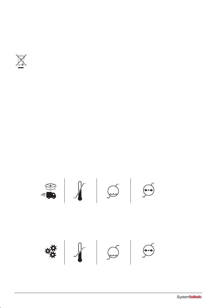
Storage and transportation
If the lift is not to be used for some time or e.g., during transport, we recommend that the emergency stop button be
pressed in. The lift should be transported and stored in -10 ° C to + 50 ° C and in normal humidity, 20% to 80% non-
condensing. The air pressure should be between 700 and 1060 hPa. See also Technical Information below, and marked
on the device. Leftmost symbol indicates storage and transportation. Let the lift reach room temperature before the
batteries are charged or the lift is used. The lift should not be stored so that it is exposed to dust, or so that the battery is
exposed to direct sunlight.
Operation
The operating environment should be 5 °C to 40°C, relative humidity 20% to 80% non-condensing, and atmospheric
pressure 700 to 1060 hPa. See also Technical Information below, and marked on the device. Leftmost symbol indicates
operating condition.
Service agreements
Direct Healthcare Group offers the possibility of service agreements for maintenance and regular testing of your mobile
lift. Contact your local Direct Healthcare Group representative.
40°C
5°C
50°C
-10°C
1060
hPa
700
hPa
1060
hPa
700
hPa
%
80%
20%
%
80%
20%
40°C
5°C
50°C
-10°C
1060
hPa
700
hPa
1060
hPa
700
hPa
%
80%
20%
%
80%
20%
14 IFU

Symbols
White/blue
Read user manual
May not be discarded in domestic waste
The product complies with the requirements of the Medical Device Regulation (EU) 2017/745
Type BF, according to the degree of protection against electric shock.
The device is intended for indoor use.
Class lI equipment
Important
Be observant
Red/ black
Do not puch or pull the lift by the actuator
Duty cycle:
2 min in active (ON) mode,
18 min in rest (OFF) mode.
Mass
Weight (mass) of the device, the safe working
load of the device, and the sum total. All in kg.
MiniLift200
25151 200
SWL Total
15IFU

Lifting speed 35 mm/s without load
Batteries Two 12V, 2.9 Ah valve-regulated, sealed, lead accumulator (gel-type batteries)
Charger Max. 400mA
Motor (mast) DC 24 V, 10.5 Ah. Operating time: 10% maximum continuous operation for 2 minutes
Push: 7500N
Motor (base) DC 24 V, 12.3 Ah. Operating time: 10% maximum continuous operation for 2 minutes
Push: 2000N
Sound level 55.8 dB(A)
Material Steel
Emergency lowering Manual and electrical
Castors Front 3.9”, 100 mm, back 3.9”, 100 mm
Weight 49 kg/108 lbs
IP class IP X4
Expected lifetime 10 years
Expected lifetime
of accessories
Consult the manual or information sheets regarding the respective accessories
Operating forces buttons on
hand control
4 N
Max. load 200 kg/ 441 lbs
Operating environment 5 °C to 40°C, relative humidity 20% to 80% non-condensing, and atmospheric
pressure 700 to 1060 hPa.
Storage and transportation
environment
-10 °C to + 50 °C, relative humidity 20% to 80% non-condensing, and atmospheric
Environment pressure 700 to 1060 hPa.
Technical Information
16 IFU

The lift has been tested for compliance with current regulatory standards regarding its capacity to block EMI
(electromagnetic interference) from external sources. The lift has been tested according to IEC60601-1-2 Edition 4.
Some procedures can help reduce electromagnetic interferences, such as following the intended environment: Home
Healthcare Environment and Professional Healthcare facility environment.
The following are exceptions to the above intended environment: Near HF Surgical Equipment and in a RF Shielded
room of an ME SYSTEM for magnetic resonance imaging.
WARNING: In case the unit stops operating, behaves in an unexpected way, or moves unintentionally due to possible
electromagnetic disturbance or interference, the unit should be switched off. It should be switch on again and its
function should be verified before use. If the problem remains the unit should be used in another room or environment.
In case of other equipment being disturbed, its function should be verified before using again.
WARNING: In case the unit stops operating or behaving in an unexpected way due to possible EM disturbance, the
unit should be switched off. Its function should be verified, and the equipment should be used in another room or
environment. In case of other equipment being disturbed, its function should be verified before using again.
WARNING: Use of this equipment adjacent to or stacked with other equipment should be avoided because it could result
in improper operation. If such use is necessary, this equipment and the other equipment should be observed to verify
that they are operating normally.
WARNING: Portable RF communications equipment (including peripherals such as antenna cables and external
antennas) should be used no closer than 30 cm (12 inches) to any part of the lift including cables specified by the
manufacturer. Otherwise, degradation of the performance of this equipment could result.
Electromagnetic Compatibility (EMC)
17IFU

18 IFU
MiniLift200 är en mobil uppresningslyft som är utvecklad för att, på ett så skonsamt sätt som möjligt, hjälpa brukaren
att resa sig från sittande till stående position. Tillsammans med rätt lyfttillbehör får brukaren stöd under fötterna mot
framsidan av underbenen samt bakom ryggen, vilket ger en trygg och säker uppresning. Konstruktionen lyfter brukaren
framåt och uppåt i ett helt naturligt rörelsemönster samtidigt som benmuskler och balans tränas.
1. Lyftarm
2. Krokar till lyftselen
3. Handkontroll
4. Underbensstöd
5. Fotplatta
6. Bakre hjul med broms
7. Batteri
8. Nödstopp
9. Inställning av underbensstöd
10. Manuell nödsänkning
11. Elektrisk nödsänkning
12. Laddningslampa
13. Främre hjul
14. Låsmekanism för justering av lyftarm
Läs alltid bruksanvisningen
• Läs alltid bruksanvisningarna för alla hjälpmedel som används vid en förflyttning.
• Förvara bruksanvisningen tillgänglig för användare av produkten.
• Se till att du alltid har rätt version av bruksanvisningen.
• Den senaste versionen finns att ladda ned från vår hemsida www.directhealthcaregroup.com
• Lyften får bara användas av personer som fått utbildning i hanteringen av den.
• Lyften får under inga omständigheter modifieras.
3
14
2
1
7
10
4
9
5
6
13
811
12
Bruksanvisning - Svenska
MiniLift200
19IFU

Montering av MiniLift200
Kontrollera att samtliga delar finns med:
Lyftmotor, kontrollbox, batteripack, underrede med breddningsmotor, fotplatta, underbensstöd, handkontroll med kabel,
manual samt laddare.
Anslut kablarna: Kabel till handkontroll i HS, kabel till lyftmotorn på
lyftpelaren i uttag M1 och kabel till breddningsmotorn till uttag M2.
HS M1 M2
Dekal om säkerhetsbrytare: Välj en dekal på passande språk, som informerar
om hur du återställer säkerhetsbrytaren. Klistra dekalen på lyftarmens
ovansida.
HOLD2 sec
1
HOLD2 sec
2
PUSH
PUSH
Visuell inspektion
• Inspektera förpackningen för att upptäcka eventuella skador.
• Kontrollera att rätt produkt har levererats.
• Gör regelbundna kontroller av lyftens funktioner.
• Kontrollera att materialet är fritt från skador.
Före användning
• Kontrollera att alla delar/komponenter finns med i förpackningen.
• Kontrollera att alla godkända tillbehör finns med i förpackningen.
• Kontrollera att kvalitetsgarantidokumentet finns med i förpackningen. Spara det här dokumentet för eventuella
framtida kontakter med tillverkaren.
• Kontrollera att lyften är korrekt monterad.
• Kontrollera lyftfunktionen och funktionen för att justera benbreddningen.
• Kontrollera körfunktionen i alla riktningar.
• Kontrollera infästningen av lyftbygeln samt urkrokningsskyddets funktion.
• Kontrollera att låsstiftet med snabbkoppling för ställdonet är korrekt monterat.
Säkerhetskontroll
20 IFU
Table of contents
Languages:
Other DHG Medical Equipment manuals

DHG
DHG RoMedic EasyRoll Sliding Sheet User manual

DHG
DHG RoMedic LiftSeat User manual

DHG
DHG Bure Standard/S User manual

DHG
DHG WendyLett2Way User manual

DHG
DHG SystemRoMedic Eva400 User manual

DHG
DHG Bure XL User manual

DHG
DHG Bure Rise & Go DB User manual

DHG
DHG SystemRoMedic Bure Rise & Go DB User manual

DHG
DHG Raizer M User manual

DHG
DHG RoMedic StretcherBar 70200006 User manual


