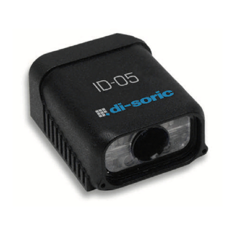
Di-soric ID-04 User manual

ID-04 Imager
User’s Manual
ID-04 User’s Manual

ii ID-04 Imager User’s Manual
Copyright and Disclaimer
Copyright ©2010
ISO 9001 Certified
Issued by TüV USA
All rights reserved. The information contained herein is proprietary and is provided solely for the purpose
of allowing customers to operate and/or service di-soric manufactured equipment and is not to be
released, reproduced, or used for any other purpose without written permission of di-soric.
Throughout this manual, trademarked names might be used. Rather than place a trademark (™) symbol
at every occurrence of a trademarked name, we state herein that we are using the names only in an editorial
fashion, and to the benefit of the trademark owner, with no intention of infringement.
Disclaimer
The information and specifications described in this manual are subject to change without notice.
Latest Manual Version
For the latest version of this manual, see the Download Center on our web site at:
www.di-soric.com.
Technical Support
Warranty and Terms of Sale
For Standard Warranty information contact:
di-soric GmbH & Co. KG
Steinbeisstraße 6
DE-73660 Urbach
Fon: +49 (0) 71 81 / 98 79 - 0
Fax: +49 (0) 71 81 / 98 79 - 179
www.di-soric.com

ID-04 Imager User’s Manual iii
Introduction
Table of Contents
Chapter 1 Quick Start
Step 1 Check Required Hardware ...........................................................1-2
Step 2 Connect the System .....................................................................1-3
Step 3 Position Imager and Symbol ........................................................1-4
Step 4 Install di-soric ID...........................................................................1-5
Step 5 Select Model.................................................................................1-6
Step 6 Select Communications Protocol .................................................1-7
Step 7 Locate the Symbol in the FOV .....................................................1-8
Step 8 Calibrate Settings .......................................................................1-10
Step 9 Test Read Rate ..........................................................................1-11
Step 10 Configure the Imager in di-soric ID...........................................1-12
Step 11 Make Menu Changes and Save in di-soric ID ..........................1-13
Chapter 2 Using di-soric ID
EZ Mode ..................................................................................................2-2
Application Mode .....................................................................................2-3
Menu Toolbar...........................................................................................2-4
Connecting............................................................................................ 2-12
View ...................................................................................................... 2-13
Navigating in di-soric ID........................................................................ 2-14
Send/Receive Options .......................................................................... 2-15
Using EZ Trax........................................................................................2-17
Chapter 3 Communications
Communications by di-soric ID ................................................................3-2
Communications Serial Commands ........................................................3-3
Host Port Connections.............................................................................3-4
Host Port Protocol....................................................................................3-5
ACK/NAK Options....................................................................................3-7
Polling Mode Options...............................................................................3-8
RS-422 Status .........................................................................................3-9
Auxiliary Port Connections.....................................................................3-10
Auxiliary Port System Data Status.........................................................3-18
Daisy Chain Autoconfigure ....................................................................3-19
Response Timeout.................................................................................3-20
LRC Status ............................................................................................3-21
Protocol Configuration Examples ..........................................................3-22
USB HID Interface .................................................................................3-23
ASCII Character Entry Modifier .............................................................3-32
Preamble ...............................................................................................3-33
Postamble..............................................................................................3-34
Chapter 4 Calibration
Calibration Serial Commands ..................................................................4-2

iv ID-04 Imager User’s Manual
Table of Contents
Calibration Overview ............................................................................... 4-2
Calibration Options .................................................................................. 4-3
Calibration by di-soric ID ....................................................................... 4-10
Initiating Calibration ............................................................................... 4-12
Additional Notes about Calibration ........................................................ 4-17
Chapter 5 Read Cycle
Read Cycle by di-soric ID ........................................................................ 5-2
Read Cycle Serial Commands ................................................................ 5-3
Read Cycle Setup.................................................................................... 5-4
Multisymbol.............................................................................................. 5-5
Trigger Mode and Duration...................................................................... 5-6
External Trigger Polarity ........................................................................ 5-11
Serial Trigger ......................................................................................... 5-12
Start Trigger Character (Non-Delimited)................................................ 5-13
Stop Trigger Character (Non-Delimited)................................................ 5-13
End of Read Cycle................................................................................. 5-14
Capture Mode........................................................................................ 5-16
Capture Timing ...................................................................................... 5-20
Image Processing Timeout.................................................................... 5-22
Image Storage ....................................................................................... 5-23
Minimum Good Reads........................................................................... 5-25
Setting Up the Imager for EZ Trax......................................................... 5-26
Chapter 6 Symbologies
Symbologies by di-soric ID ...................................................................... 6-2
Symbologies Serial Commands .............................................................. 6-3
Data Matrix .............................................................................................. 6-4
QR Code.................................................................................................. 6-6
Code 39 ................................................................................................... 6-7
Code 128 / EAN 128.............................................................................. 6-10
BC412.................................................................................................... 6-13
Interleaved 2 of 5................................................................................... 6-14
Code 93 ................................................................................................. 6-17
Codabar................................................................................................. 6-18
UPC / EAN............................................................................................. 6-21
GS1 DataBar (RSS) .............................................................................. 6-25
PDF417 ................................................................................................. 6-27
MicroPDF417......................................................................................... 6-29
Composite ............................................................................................. 6-30
Narrow Margins / Symbology Identifier.................................................. 6-31
Background Color.................................................................................. 6-33
Chapter 7 I/O Parameters
I/O Parameters by di-soric ID .................................................................. 7-2
I/O Parameters Serial Commands........................................................... 7-3
Symbol Data Output ................................................................................ 7-4

ID-04 Imager User’s Manual v
Introduction
No Read Message ...................................................................................7-6
Bad Symbol Message..............................................................................7-8
No Symbol Message................................................................................7-8
1D / Stacked Symbology Qualification.....................................................7-9
2D Symbology Qualification...................................................................7-10
Read Duration Output............................................................................7-16
Output Indicators ...................................................................................7-17
Beeper ...................................................................................................7-21
LED Configuration .................................................................................7-22
Serial Verification...................................................................................7-23
EZ Button...............................................................................................7-25
EZ Button Modes ...................................................................................7-27
Configurable Output 1............................................................................7-29
Trend Analysis Output 1 ........................................................................7-32
ISO/IEC 16022 Symbol Quality Output 1...............................................7-35
Diagnostic Output 1 ...............................................................................7-38
Configurable Output 2............................................................................7-39
Trend Analysis Output 2 ........................................................................7-39
ISO/IEC 16022 Symbol Quality Output 2...............................................7-39
Diagnostic Output 2 ...............................................................................7-39
Configurable Output 3............................................................................7-40
Trend Analysis Output 3 ........................................................................7-40
ISO/IEC 16022 Symbol Quality Output 3...............................................7-40
Diagnostic Output 3 ...............................................................................7-40
Power-On/Reset Counts........................................................................7-41
Time Since Reset ..................................................................................7-42
Service Message ...................................................................................7-43
Frame Information .................................................................................7-44
Image Output .........................................................................................7-45
Database Identifier Output.....................................................................7-48
Quality Output........................................................................................7-49
Configuring EZ Trax Output...................................................................7-50
Chapter 8 Symbol Quality
Symbol Quality Serial Commands ...........................................................8-2
Overview of Symbol Quality.....................................................................8-3
Symbol Quality by di-soric ID...................................................................8-4
Symbol Quality Separator / Data Matrix Output Mode.............................8-8
ISO/IEC 16022 Symbol Quality Output..................................................8-10
ISO/IEC 16022 Symbol Quality Output by di-soric ID............................8-12
di-soric Symbol Quality Output ..............................................................8-13
di-soric Symbol Quality Output by di-soric ID ........................................8-16
Chapter 9 Matchcode
Matchcode by di-soric ID .........................................................................9-2
Matchcode Serial Commands..................................................................9-2

vi ID-04 Imager User’s Manual
Table of Contents
Overview of Matchcode ........................................................................... 9-3
Matchcode Type ...................................................................................... 9-4
Match Replace......................................................................................... 9-9
Mismatch Replace ................................................................................. 9-10
New Master Pin ..................................................................................... 9-11
Chapter 10 Camera and IP Setup
Camera and IP Setup by di-soric ID ...................................................... 10-2
Camera and IP Setup Serial Commands .............................................. 10-3
Video ..................................................................................................... 10-4
Evaluation.............................................................................................. 10-5
Calibration ............................................................................................. 10-9
Window of Interest............................................................................... 10-10
Configuration Database....................................................................... 10-13
Dynamic Setup .................................................................................... 10-14
Pixel Sub-Sampling ............................................................................. 10-15
Camera................................................................................................ 10-16
Focal Distance..................................................................................... 10-18
Focal Distance Table (Read-Only) ...................................................... 10-19
IP Threshold ........................................................................................ 10-20
Number of Symbols in Field of View.................................................... 10-22
Image Processing Timeout.................................................................. 10-23
Damaged Symbol ................................................................................ 10-24
IP Mode ............................................................................................... 10-25
Hollow Mode........................................................................................ 10-26
Mirrored Image .................................................................................... 10-27
Illumination Brightness ........................................................................ 10-28
Skew Correction .................................................................................. 10-29
Chapter 11 Configuration Database
Configuration Database Serial Commands ........................................... 11-2
Number of Active Indexes ..................................................................... 11-3
Configuration Database Status.............................................................. 11-4
Database Mode ..................................................................................... 11-9
Save Current Settings to Configuration Database............................... 11-14
Load Current Settings from Configuration Database........................... 11-15
Request Selected Index Settings ........................................................ 11-16
Request All Configuration Database Settings ..................................... 11-17
Chapter 12 Terminal
Terminal Window................................................................................... 12-2
Find........................................................................................................ 12-3
Send ...................................................................................................... 12-4
Macros................................................................................................... 12-5
Terminal Window Menus ....................................................................... 12-6
Chapter 13 Utilities
Serial Utility Commands ........................................................................ 13-2

ID-04 Imager User’s Manual vii
Introduction
Read Rate..............................................................................................13-4
Counters ................................................................................................13-5
Device Control .......................................................................................13-7
Master Database ...................................................................................13-8
Firmware..............................................................................................13-14
Bar Code Configuration .......................................................................13-17
Default / Reset / Save..........................................................................13-18
Imager Status Requests ......................................................................13-20
Other Operational Serial Commands...................................................13-22
Chapter 14 Output Format
Output Format Serial Commands ..........................................................14-2
Output Format Status ............................................................................14-3
Format Assign........................................................................................14-4
Format Extract .......................................................................................14-5
Format Insert .........................................................................................14-7
Output Filter Configuration.....................................................................14-9
Ordered Output Filter...........................................................................14-13
Appendices
Appendix A General Specifications ........................................................ A-2
Appendix B Electrical Specifications....................................................... A-5
Appendix C Serial Configuration Commands ......................................... A-6
Appendix D Communications Protocol ................................................. A-12
Appendix E ASCII Table ....................................................................... A-21
Appendix F Interface Standards ........................................................... A-22
Appendix G Object Detector ................................................................. A-23
Appendix H Operational Tips................................................................ A-24
Appendix I USB-to-Serial Virtual COM Port Driver ............................... A-25
Appendix J Glossary of Terms.............................................................. A-28
Index

viii ID-04 Imager User’s Manual
About the ID-04 Imager
About the ID-04 Imager
The key features of the ID-04 are:
• A multi-function EZ button for location, calibration, and symbol reading.
• A target pattern symbol locator that identifies the center point of the field of view.
• A green flash (visible from all angles) to signal a successful read.
• Ability to read both 2D and linear symbols.
• Ability to read difficult and damaged symbols.
• USB, RS-232, RS-422 connectivity options.
• Standard Density and Low Density options.
About This Manual
This manual provides complete information on setting up, installing, and configuring the
Imager. The chapters are presented in the order in which an Imager might be set up and
made ready for operation.
Highlighting
Commands are highlighted in rust bold. Cross-references and web links are highlighted
in blue bold. References to di-soric ID, its toolbar headings (Communications, Read
Cycle, Symbologies, etc.), menu topics, and other points of emphasis, are highlighted in
Bold Initial Caps. References to topic headings within this manual or other documents
are enclosed in quotation marks.
Host Communications
There are four ways to configure and test the ID-04:
1. EZ button.
2. di-soric’s Windows-based di-soric ID (Setup Program), which offers point-and-click
ease of use and visual responses to user adjustments.
3. Serial commands, such as <K100,1>, that can be sent from di-soric ID’s Terminal
window or another terminal program.
4. The tree control menus and graphic interfaces in di-soric ID’s App Mode.

ID-04 Imager User’s Manual ix
Introduction
Warning and Caution Summary
• Viewing the ID-04’s LED output with optical instruments such as magnifiers, eye loupes,
or microscopes within a distance of 100 mm could cause serious eye injury.
• Maximum LED output: .564 mW.
• Wavelength: 470 nm; 525 nm; 617 nm.
• Location of the ID-04’s LED aperture window:
CAUTION: Use of controls or adjustments or performance of procedures other than those
specified herein may result in hazardous radiation exposure.
IMPORTANT: The ID-04 is intended for connection to a UL-listed direct plug-in power unit
marked Class II and rated 5 VDC at 3 Watts, or greater if using electrical accessories.
European models must use a similarly rated Class I or Class II power supply that is certified
to comply with standard for safety EN 60950.
WARNING
LED LIGHT
DO NOT VIEW DIRECTLY WITH OPTICAL INSTRUMENTS
CLASS 1 LED PRODUCT
LED Output: .564 mW. Wavelength: 470 nm; 525 nm; 617 nm.
IEC 60825-1:1993+A1:1997+A2:2001
LED Aperture Window

xID-04 Imager User’s Manual
Statement of Agency Compliance
Statement of Agency Compliance
The ID-04 Imager has been tested for compliance with FCC (Federal Communications
Commission) regulations and has been found to conform to all applicable FCC Rules and
Regulations.
To comply with FCC RF exposure compliance requirements, this device must not be co-located
or operate in conjunction with any other antenna or transmitter.
Changes or modifications not expressly approved by the party responsible for compliance
could void the user’s authority to operate the equipment.
The ID-04 Imager has been tested for compliance with CE (Conformité Européenne)
standards and guidelines, and has been found to conform to applicable CE standards,
specifically
the EMC requirements
EN 55024, ESD EN 61000-4-2, Radiated RF Immunity
EN 61000-4-3, ENV 50204, EFT EN
61000-4-4, Conducted RF Immunity EN 61000-4-6, EN
55022, Class B Radiated Emissions
, and Class B Conducted Emissions.
The ID-04 Imager has been tested by an independent electromagnetic compatibility laboratory
in accordance with the applicable specifications and instructions.

ID-04 Imager User’s Manual xi
Introduction
Statement of RoHS Compliance
All di-soric ID readers are RoHS-Compliant.
These products meet all the requirements of the European Parliament and the Council of the
European Union for RoHS compliance. In accordance with the latest requirements, our
RoHS-compliant products and packaging do not contain intentionally added Deca-BDE,
Perfluorooctanes (PFOS) or Perfluorooctanoic Acid (PFOA) compounds above the
maximum trace levels. To view the documents stating these requirements, please visit:
http://eur-lex.europa.eu/LexUriServ/LexUriServ.do?uri=CELEX:32002L0095:EN:HTML
and
http://eur-lex.europa.eu/LexUriServ/LexUriServ.do?uri=OJ:L:2006:372:0032:0034:EN:PDF
Please contact your sales manager for a complete list of di-soric’s RoHS-Compliant
products.
This declaration is based upon information obtained from sources which di-soric believes to be reliable, and from
random sample testing; however, the information is provided without any representation of warranty, expressed or
implied, regarding accuracy or correctness. di-soric does not specifically run any analysis on our raw materials or
end product to measure for these substances.
The information provided in this certification notice is correct to the best of di-soric’s knowledge at the date of
publication. This notice is not to be considered a warranty or quality specification. Users are responsible for
determining the applicability of any RoHS legislation or regulations based on their individual use of the product.

xii ID-04 Imager User’s Manual
Statement of RoHS Compliance

ID-04 Imager User’s Manual 1-1
1 Quick Start
Contents
This section is designed to get your ID-04 Imager up and running quickly, using the EZ
button or di-soric ID (Setup Program). Following these steps will allow you to get a sense
of the Imager’s capabilities and to test sample symbols.
Detailed setup information for installing the Imager into your actual application can be
found in the subsequent chapters.
Step 1 Check Required Hardware ................................................................................................1-2
Step 2 Connect the System ..........................................................................................................1-3
Step 3 Position Imager and Symbol..............................................................................................1-4
Step 4 Install di-soric ID................................................................................................................1-5
Step 5 Select Model......................................................................................................................1-6
Step 6 Select Communications Protocol.......................................................................................1-7
Step 7 Locate the Symbol in the FOV...........................................................................................1-8
Step 8 Calibrate Settings ........................................................................................................... 1-10
Step 9 Test Read Rate .............................................................................................................. 1-11
Step 10 Configure the Imager in di-soric ID............................................................................... 1-12
Step 11 Make Menu Changes and Save in di-soric ID .............................................................. 1-13

1-2 ID-04 Imager User’s Manual
Check Required Hardware
Step 1 — Check Required Hardware
Item Description Part Number
1ID-04 Imager ID-04-IM1-X-X
4Comm. Cable VSID-SD-5/15-S
Toadditionalimagers
orterminatingresistor
To host
Hardware Required (RS-232 / RS-422)
Caution: Be sure that all cables are connected BEFORE applying power to a
system with an external power source (RS-232 / RS-422). Always power down
BEFORE disconnecting any cables.
Hardware Required (USB)

ID-04 Imager User’s Manual 1-3
Quick Start
Step 2 — Connect the System
Connecting by RS-232 / RS-422
• Connect the Imager (1) to the interface (2).
• Connect the comm. cable (4) to the host (5) and to the host connector on the (2).
• Connect power supply (3) to the (2).
• Apply power to the Imager.
Connecting by USB
• Plug the ID-04 Imager’s USB cable into a host USB port. The host will power the Imager.
Hardware Configuration
(RS-232 / RS-422)
Hardware Configuration
(USB)
Caution: Be sure that all cables are connected BEFORE applying power to a
system with an external power source (RS-232 / RS-422). Always power down
BEFORE disconnecting any cables.
Toadditionalimagers
orterminatingresistor
To host

1-4 ID-04 Imager User’s Manual
Position Imager and Symbol
Step 3 — Position Imager and Symbol
• Position the Imager at a distance from the symbol that matches the factory pre-set focal
distance. For example, if your ID-04 is pre-set at 4”, position the Imager’s parting line 4”
from the symbol.
• Tip the Imager relative to the symbol to avoid the glare of direct (specular) reflection. The
case parting line should be perpendicular to the plane of the symbol by either pitching the
symbol or the Imager as shown.
• Position the Imager in a place with as little ambient light as possible.
• Symbols can be rotated (tilted) at any angle; however, for best results symbols should
be aligned with the FOV (field of view).
• In the case of linear symbols, aligning the bars in the direction of their movement (“ladder”
orientation) will minimize the chances of blurring, and will produce better reads.
• Avoid excessive skew or pitch. Maximum skew is ±30°; maximum pitch is ±30°.
Note: For instant setup and validation, the ID-04 can be hand-held or placed on its side.
For accuracy, however, di-soric’s mounting arm adapter kits are recRPPHQGHG
Imager Position Relative to Symbol

ID-04 Imager User’s Manual 1-5
Quick Start
Step 4 — Install di-soric ID
Setup Program (di-soric ID) is di-soric’s proprietary setup and testing application. The
purpose of di-soric ID is to provide a quick and easy way to set up and configure di-soric read-
ers.
When the ID-04 is connected to a host computer (Windows Vista, XP, or 2000), di-soric
ID can be used to configure reader settings and to set up communications between the
reader and host.
If installing from the di-soric Tools USB Stick:
1. Insert the di-soric Tools USB Stick in your computer.
2. Select di-soric ID Software from the navigation bar at the left of the screen.
3. Click on di-soric ID Software under the Current Version heading.
4. Click the Run button and follow the prompts in the di-soric ID Setup Wizard.
Note: During installation, you may see an Internet Explorer Security Warning that
states: “The publisher could not be verified.” If you see this warning, click Run to
continue installation.
If downloading from the web:
1. Go to the Download Center at www.di-soric.com.
2. Create a new member account or, if you are already a member, enter your user name
and password.
Navigate to the “di-soric Software” section of the Download Center (near the
top of the page).
3. Click on the link showing the latest version of di-soric ID. Extract the di-soric ID
installation files to a location of your choice on the host computer. Note where your di-
soric ID.exe file is stored on your hard drive.
4. At the end of the installation process, the following icon will appear on your desktop:
5. Click the di-soric ID icon to start the program.
System Requirements for di-soric ID
• 166 MHz Pentium processor (recommended)
• Windows Vista, XP, or 2000 operating system
• Internet Explorer 5.0 or higher
• 64 MB minimum RAM
• 40 MB minimum disk space
• 800 x 600 pixel minimum 256 color display

1-6 ID-04 Imager User’s Manual
Select Model
Step 5 — Select Model
When you start di-soric ID, the following menu will appear:
1. Click the ID-04 button and then click OK. If you do not want to make this selection
every time you start di-soric ID, uncheck “Show this window at Startup”.
2. Select the default reader name (ID-04-1), or type a name of your choice in the
Description text field and click OK.
3. Click Yes when this dialog appears:
Note: If you need to select another reader model later, click the Switch Model button
near the top of the screen.

ID-04 Imager User’s Manual 1-7
Quick Start
Step 6 —Select Communications Protocol
Important: The Imager is in Continuous Read Mode by default. For best connection
results, be sure that no symbols are within the Imager’s field of view while attempting to
connect.
• When the Select Protocol dialog appears, choose your connection protocol and click Next.
• If you are using an RS-232 interface and your connection attempt fails, click the Autoconnect
button, select a different communications port, and try again.
When you are connected, you will see the green connection indicator in the status bar
at the bottom right of your screen.
If you choose USB protocol:
If you choose RS-232 protocol:
USB:
RS-232:
• Select the
ID-
04
from the
Select
Device menu
and click
Finish.
• Click Connect.
Note: If your RS-232 host
settings cannot be
changed to match the
Imager’s settings, check
the Force Connect box.

1-8 ID-04 Imager User’s Manual
Locate the Symbol in the FOV
Step 7 — Locate the Symbol in the FOV
• Move the symbol or the Imager so that the blue target pattern is centered over the symbol.
At 2 to 3 inches, the pattern resembles an X. At 3 to 6 inches, the pattern resembles a V.
It is important for the whole symbol to fall within the field of view (FOV) of the Imager.
The field of view is what appears in di-soric ID’s Locate/Calibrate window.
Locate by EZ Button
If you are not connected to a host computer, the EZ button will allow you to locate a symbol
in the Imager’s FOV.
• Hold down the EZ button for about one second and release when you hear one short beep.
The amber 20% LED will turn on, and you will see the blue target pattern projected from the
front of the Imager.
• Center the target pattern on the symbol.
Note: To end all EZ button functions, press the EZ button once and quickly release.
Center on object
in field of view.
Target pattern shown as it would appear between 3 and 6 inches.
Table of contents
Other Di-soric Laboratory Equipment manuals
