Figures
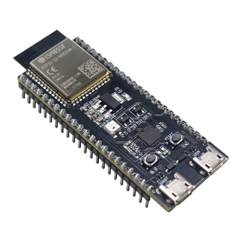
Figure 1: DA14695 USB Kit................................................................................................................... 5
Figure 2: DA14695 USB Kit - Top Side................................................................................................. 6
Figure 3: DA14695 USB Kit - Bottom Side............................................................................................ 7
Figure 4: Test Points Topology (BOTTOM View).................................................................................. 9
Figure 5: Block Diagram of DA14695 USB Kit.................................................................................... 10
Figure 6: DA14695 Schematic ............................................................................................................ 12
Figure 7: RF Matching Circuit, Printed Antenna, and SMA Connector............................................... 17
Figure 8: RF Port, RF Connector, RF Matching, and SMD Chip Antenna.......................................... 17
Figure 9: QSPI Data Flash .................................................................................................................. 18
Figure 10: Available packages for QSPI Data Flash........................................................................... 18
Figure 11: Reset Circuit....................................................................................................................... 19
Figure 12: RESET Push Button (K2)................................................................................................... 19
Figure 13: General Purpose Push Button ........................................................................................... 19
Figure 14: General Purpose Push Button K1 (Populated at TOP)...................................................... 20
Figure 15: Debugging DIP Switch....................................................................................................... 20
Figure 16: Debugging DIP switch........................................................................................................ 20
Figure 17: General Purpose Red LED ................................................................................................ 21
Figure 18: General Purpose Red LED D7........................................................................................... 21
Figure 19: Mikrobus™ Pin Assignment ............................................................................................... 21
Figure 20: J15, J16, J17, and J18 Female Sockets (Must Be Soldered by Users)............................. 22
Figure 21: Guides for Proper Mikrobus™ Click Boards Insertion ....................................................... 22
Figure 22: Mikrobus™ Pin Assignment............................................................................................... 22
Figure 23: GND Support Point ............................................................................................................ 23
Figure 24: GND Support Point (Must Be Placed by Users) ................................................................ 23
Figure 25: Over Voltage Protection Circuit.......................................................................................... 23
Figure 26: Over Current Protection Circuit on V30 Power Rail........................................................... 24
Figure 27: USB HUB Circuitry............................................................................................................. 24
Figure 28: Debugging Processor UART And JTAG Interface (U4)..................................................... 25
Figure 29: DA14695 USB Kit Power Tree........................................................................................... 26
Figure 30: Linear Voltage Regulators (LDOs) U2 And U3.................................................................. 26
Figure 31: PCB Cross Section ............................................................................................................ 28
Figure 32: DA14695 SoC Section....................................................................................................... 29
Figure 33: UART & JTAG Interface Chip Section............................................................................... 30
Figure 34: USB Hub Section ............................................................................................................... 31
Figure 35: Bill of Materials (BOM)....................................................................................................... 32
Tables
Table 1: Test Points Assignment........................................................................................................... 8
Table 2: USB Kit Pin Assignment........................................................................................................ 14
Table 3: Y1 (32 MHz crystal) characteristics....................................................................................... 16
Table 4: Y2 (32.768 kHz crystal) characteristics................................................................................. 16
Table 5: RF Components Names and Values..................................................................................... 17
Table 6: DA14695 power configurations............................................................................................. 27


