Figures
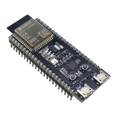
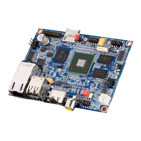
Figure 1: PCB of the DA14585 Range Extender (321-13-B) ................................................................ 7
Figure 2: Block Diagram of Range Extender (321-13-B) .................................................................... 10
Figure 3: DA14585 Range Extender (321-13-B) on a DA14580 PRO-Dev.Kit Motherboard ............. 11
Figure 4: Layout of the DA14585 Range Extender daughterboard..................................................... 11
Figure 5:DA14585 QFN40 SoC DA14585 Range Extender ............................................................... 13
Figure 6: RF Front End signal paths ................................................................................................... 14
Figure 7: RF Front End schematic ...................................................................................................... 14
Figure 8: SKY66111-11 Power Amplifier............................................................................................. 15
Figure 9: SKY66111-11 Front End Module - overview........................................................................ 16
Figure 10: BLE_DIAGCNTL_REG (0x40000050) register specification............................................. 17
Figure 11: BLE_DIAGCNTL2_REG (0x4000020C) register specification .......................................... 17
Figure 12: BLE_DIAGCNTL3_REG (0x40000210) register specification........................................... 17
Figure 13: Low Pass Filter (L7&L5=2.7nH, C18=1.2pF)..................................................................... 19
Figure 14: T-shaped, 3-poles, Low Pass Filter.................................................................................... 19
Figure 15: Printed Inverted F Antenna geometry................................................................................ 20
Figure 16: Matching network for printed antenna................................................................................ 20
Figure 17: S parameters of Printed IFA and Matching Network.......................................................... 21
Figure 18: Radiation diagram for the board placed vertically.............................................................. 22
Figure 19: Radiation diagram for the board placed horizontally.......................................................... 22
Figure 20: SKY66111-11 POUT vs VCC & VBIAS (PIN=-1dBm).............................................................. 23
Figure 21: Power regulation circuit...................................................................................................... 23
Figure 22: TX Output Power using PWM mode, 3 channels............................................................... 24
Figure 23: PWM Duty Cycle vs TX Output Power and VCC............................................................... 25
Figure 24: Top view of PCBA.............................................................................................................. 29
Figure 25: Bottom view of PCBA......................................................................................................... 29
Figure 26: RX Sensitivity, Dirty Transmitter OFF, Payload: PRBS9, Length: 37, MAX_POWER ...... 35
Figure 27: RX Sensitivity, Dirty Transmitter, Payload: PRBS9, Length: 37, MAX_POWER............... 36
Figure 28: Nominal Average TX Output Power per channel vs all power levels................................. 37
Figure 29: Maximum Output Power, CH00 ......................................................................................... 42
Figure 30: Maximum Output Power, CH19 ......................................................................................... 42
Figure 31: Maximum Output Power, CH39 ......................................................................................... 43
Figure 32: Harmonics Level, Lowest Frequency, CH00...................................................................... 45
Figure 33: Harmonics Level, Lowest Frequency, CH19...................................................................... 45
Figure 34: Harmonics Level, Lowest Frequency, CH39...................................................................... 46
Figure 35: Radiated Emissions in Lower Restricted Band, CH00....................................................... 48
Figure 36: Radiated Emissions in Upper Restricted Band, CH39....................................................... 48
Figure 37: Conducted Emissions in Lower Band Edge, CH00............................................................ 49
Figure 38: Conducted Emissions in Upper Band Edge, CH39............................................................ 50
Figure 39: TX spurious emissions radiated, CH00.............................................................................. 52
Figure 40: RX spurious emissions radiated, CH00 ............................................................................. 52
Figure 41: Full size IFA used in DA14585 Range Extender with dimensions..................................... 53
Figure 42:DA14585 Range Extender board layout snapshot.............................................................. 54
Figure 43: Placement of filter and matching network.......................................................................... 55
Figure 44: Safety Information of DA14585 Range Extender............................................................... 58
Figure 45: Control pins configuration in SKY66111.h ......................................................................... 59
Figure 46: Power modes definition in SKY66111.h............................................................................. 59
Figure 47: Definition of PWM duty cycle preset values in SKY66111.h.............................................. 60
Figure 48: Global variables declaration in SKY66111.c for the range_ext_api.h................................ 60
Figure 49: Configure GPIOs for SKY66111 operation ........................................................................ 61
Figure 50: Function timer0_conf_start();............................................................................................. 61
Figure 51: Function declare_fem_gpios();........................................................................................... 62
Figure 52: Function app_range_extender_enable();........................................................................... 63
Figure 53: Function app_range_extender_sleep();............................................................................. 64
Figure 54: Function app_set_power(); ................................................................................................ 64
Figure 55: function range_ext_init();.................................................................................................... 64
Figure 56: Copy rext_sky66111-11_v1.0 folder into sdk driver........................................................... 65
Figure 57: Step 2 of adding sky66111.c to sdk_driver........................................................................ 66
Figure 58: Step 3a, Select target options............................................................................................ 66


