Figures
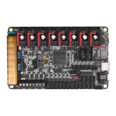
Figure 1: DA14683 USB Kit................................................................................................................... 5
Figure 2: USB Kit - Top side.................................................................................................................. 6
Figure 3: USB Kit - Bottom side ............................................................................................................ 7
Figure 4: Block diagram of DA14683 USB kit ....................................................................................... 9
Figure 5: DA14683 schematic............................................................................................................. 11
Figure 6: Chip Antenna PCB Footprint and Mechanical specifications............................................... 15
Figure 7: RF matching circuit, SMD Chip antenna and SMA connector............................................. 15
Figure 8: RF port, RF connector, RF matching and SMD Chip antenna ............................................ 16
Figure 9: Radiated measurements results - Standing position ........................................................... 16
Figure 10: Radiated measurements results - Laying position............................................................. 17
Figure 11: QSPI Flash with selectable power supply (V33 or V18) .................................................... 17
Figure 12: Reset circuit........................................................................................................................ 18
Figure 13: Reset push button.............................................................................................................. 18
Figure 14: General purpose push buttons........................................................................................... 19
Figure 15: General purpose push buttons SW1, SW2 (populated at TOP) ........................................ 19
Figure 16: General purpose push buttons SW3, SW4 (no populated at BOTTOM)........................... 19
Figure 17: General purpose LEDs....................................................................................................... 20
Figure 18: General Purpose LEDs D9 (red) & D10 (white)................................................................. 20
Figure 19: MikroBus™ pin assignment and extra DA14683 I/O & Power output................................ 21
Figure 20: J6 and J7 female sockets (must be placed and soldered by users).................................. 21
Figure 21: Proper orientation and connection between DA14683 USB Kit and a MikroBus™ click
board.................................................................................................................................................... 22
Figure 22: MikroBus™ pin assignment ............................................................................................... 22
Figure 23: GND support point ............................................................................................................. 23
Figure 24: GND support point (Male header must be placed from the user)...................................... 23
Figure 25: Over voltage protection circuit............................................................................................ 23
Figure 26: USB HUB circuitry.............................................................................................................. 24
Figure 27: Debugging processor - UART and JTAG interface............................................................ 25
Figure 28: DA14683 USB Kit power tree............................................................................................. 25
Figure 29: Linear voltage regulators (LDOs) U3 and U4..................................................................... 26
Figure 30: DA14683 power selection through SW6............................................................................ 26
Figure 31: Power selection switch SW6 (default position to 5V)......................................................... 27
Figure 32: PCB cross section.............................................................................................................. 29
Figure 33: USB Hub section................................................................................................................ 30
Figure 34: UART & JTAG interface chip section................................................................................. 31
Figure 35: DA14683 SoC section........................................................................................................ 32
Figure 36: Mikrobus™ and peripherals section................................................................................... 33
Figure 37: Bill of materials (BOM) ....................................................................................................... 34
Tables
Table 1: Various test point assignments ............................................................................................... 7
Table 2: USB kit pin assignment ......................................................................................................... 12
Table 3: Y4 (16 MHz crystal) characteristics....................................................................................... 14
Table 4: Y3 (32 kHz crystal) characteristics........................................................................................ 14
Table 5: Antenna characteristics......................................................................................................... 15
Table 6: RF Components names and values...................................................................................... 16


