Figures
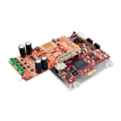
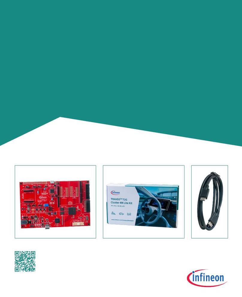
Figure 1:DK PRO, DA14531-00FXDEVKT-P DK with PRO-MB and the PRO-DBs............................. 8
Figure 2: Block Diagram of the DA14531 DK PRO Hardware Platform.............................................. 10
Figure 3: System Block Diagram of DA14531 PRO-DB......................................................................11
Figure 4: DA14531-00FXDB-P, FCGQFN24 PRO-DB_[376-04-F].....................................................11
Figure 5: DA14531-00OGDB-P, WLCSP17 PRO-DB_[376-05-E]...................................................... 12
Figure 6: DA14531 PRO-DB Power Section....................................................................................... 13
Figure 7: Power Section of DA14531 PRO-DB...................................................................................14
Figure 8: RF Section of DA14531 PRO-DB ........................................................................................15
Figure 9: Modifications Required for Performing RF Measurements..................................................15
Figure 10: DA145xx DEVKT-P PRO-MB Block Diagram....................................................................16
Figure 11: PRO-MB (376-18-x)........................................................................................................... 16
Figure 12: USB HUB Circuitry of DA14531 PRO-MB ......................................................................... 18
Figure 13: USB to UART (U12)...........................................................................................................19
Figure 14: USB to JTAG (U4).............................................................................................................. 20
Figure 15: Voltage Translator Circuitry of DA14531 PRO-MB............................................................20
Figure 16: Power Topology for DA14531 PRO-MB and PRO-DB ...................................................... 21
Figure 17: Power Circuit for DA14531 PRO-MB.................................................................................21
Figure 18: J2, Breakout Header of DA14531 PRO-MB....................................................................... 22
Figure 19: J1, Configuration Header on DA14531 PRO-MB............................................................... 23
Figure 20: RESET Circuit on DA14531 PRO-MB ...............................................................................27
Figure 21: Reset Pin Assignment on PRO-DBs for FCGQFN24 and WLCSP17 ...............................27
Figure 22: Optional Debug Port........................................................................................................... 28
Figure 23: SPI Data Flash Circuit in DA14531 DK Pro ....................................................................... 29
Figure 24: Single-wire UART for DA14531 WLCSP17 PRO-DB ........................................................ 30
Figure 25: 2-wire UART Connectivity.................................................................................................. 31
Figure 26: Full UART (4-wire) Connectivity.........................................................................................32
Figure 27: Miscellaneous Peripherals ................................................................................................. 32
Figure 28: User LED and Software Trigger Circuit and Jumpers........................................................33
Figure 29: MikroBus 2 Circuit..............................................................................................................34
Figure 30: DA14531 PRO-DB Configuration and DA14531 PRO-MB Jumpers.................................36
Figure 31: BT1 Position (Left). Battery Holder, BC2032-F1, to Be Soldered (Right).......................... 38
Figure 32: DA14531 PRO-DB Schematic (Left). DA14531 PRO-MB, Header J4 Settings (Right)..... 38
Figure 33: BT1 Position on PRO-MB (Left). Battery Holder, BU2032SM-BT-GTR, to Be Soldered
(Right)..................................................................................................................................................39
Figure 34: Default Setup of the DA14531 DK PRO with DA14531 FCGQFN24 PRO-DB .................40
Figure 35: Default Setup of the DA14531 DK PRO with a DA14531 WLCSP17 PRO-DB.................42
Figure 36: Current Measurement Circuit of DA14531 PRO-MB ......................................................... 43
Figure 37: Current Measurement Presented in Power Profiler of SmartSnippets Toolbox ................ 44
Figure 38: SmartSnippets Toolbox Configuration ............................................................................... 45
Figure 39: Hybrid Configuration .......................................................................................................... 45
Figure 40: Power Profiler of SmartSnippets Toolbox Main Window ................................................... 46
Figure 41: Power Profiler Configuration..............................................................................................46
Figure 42: Power Profiler Chart Settings.............................................................................................47
Figure 43: Free Running Capture........................................................................................................ 47
Figure 44: Triggered Capture..............................................................................................................48
Figure 45: Oscilloscope Option ...........................................................................................................48
Figure 46: Power Profiler Software Cursors........................................................................................ 49
Figure 47: Setting Offset to Zero.........................................................................................................49
Figure 48: Measuring Offset................................................................................................................50
Figure 49: Setting Calibration Offset................................................................................................... 50
Figure 50: Current Measurement Circuit Response, Indicative Graph ...............................................51
Figure 51: Current Measurement Circuit Inaccuracy, Indicative Graph..............................................52
Figure 52: A/D Converter Distortions .................................................................................................. 53
Figure 53: Disable SW3. Remove Jumper from J19:4-5.....................................................................53
Figure 54: mikroBUS Wrong Label...................................................................................................... 54
Figure 55: Full UART Configuration - CTS Issue................................................................................ 55
Figure 56: Schematic, FCGQFN24, DA14531-00FXDB-P_(376-04-F2) ............................................ 56


